130
IEEE MICROWAVE AND WIRELESS COMPONENTS LETTERS, VOL. 25, NO. 2, FEBRUARY 2015
A Temperature-Compensated LC Oscillator Using Constant-Biased Varactors Yong Wang, Student Member, IEEE, Kevin T. C. Chai, Member, IEEE, Xiaojing Mu, Minkyu Je, Senior Member, IEEE, and Wang Ling Goh, Senior Member, IEEE
Abstract—This letter presents a temperature compensated oscillator for clock generation across a wide temperature range. The proposed technique deploys the characteristics of the constant-biased varactors to nullify the overall oscillator's temperature coefficient (TC), thereby reducing the temperature drift effect on the oscillator frequency output. Fabricated on a CMOS technology, the proposed 2.09 GHz–gm-LC oscillator sees a mere frequency drift from to . The oscillator consumes 10.9 mW at 1.4 V supply, with phase noise of at a 1 MHz offset. The demonstrated technique is useful for providing accurate clock for a variety of applications, including those operating in harsh environment. Index Terms—Frequency reference, frequency source, phase-locked loop, temperature compensation, temperature sensor.
I. INTRODUCTION
M
ONOLITHIC oscillators functioning as clock generators and operating over wide temperature ranges are found in many applications such as wireless sensor nodes, food/ chemical analysis and automotive electronics. To reduce the frequency drift in oscillators requires efficient temperature compensation techniques before the much desired precisely compensated clocks, which are vital for system operations, measurements and RF communications can be realized. Various temperature compensation techniques for oscillators have been reported in literature, for example, in [1]–[3]; these temperature compensations are mainly implemented using temperature-dependent voltage biases and current sources, hence the resultant mismatches of the TCs between the biasing circuits and the oscillators limit their frequency accuracies to: [1], [2] and [3]. In [4], [5], the minimization of the TCs of passive components components, have achieved similar using various types of performances of and , respectively. In
Manuscript received July 13, 2014; revised September 25, 2014; accepted November 19, 2014. Date of publication January 07, 2015; date of current version February 10, 2015. This work was supported by the Science and Engineering Research Council of A*STAR (Agency for Science, Technology and Research), Singapore, under grant 1021650086 Y. Wang, K. T. C. Chai, and X. Mu are with the Institute of Microelectronics, A*STAR, Singapore 117685 (e-mail:
[email protected];
[email protected]). M. Je is with the Department of Information and Communication Engineering, Daegu Gyeongbuk Institute of Science and Technology, Daegu, Korea. W. L. Goh and Y. Wang are with the School of Electrical and Electronic Engineering, Nanyang Technological University, Singapore. Color versions of one or more of the figures in this paper are available online at http://ieeexplore.ieee.org. Digital Object Identifier 10.1109/LMWC.2014.2382678
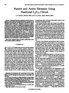
another recent technique [6], it is able to omit the temperature effects from the transistors using a pulse-excited LC tank; but then again, it only succeeded to achieve a minimum frequency inaccuracy of [6]. To improve the performance beyond the prior arts, and down to level, complex trimming methods will require a control system with tenths of bits for the digitally controlled arrays as well as a lookup table in the non-volatile memory [7]. Consequently, additional hardware cost that is often unaffordable for many applications will also be incurred. This letter presents a temperature compensation technique that makes use of constant-biased varactors, and this technique is demonstrated through application on a -gm-LC oscillator. Based on our analysis, the TC of a varactor can be regarded as a function of the bias voltage, and since the varactor is a component of the tank circuit, the TC of the -gm-LC oscillator can be directly minimized by adjusting the TC of the varactors through altering the constant bias voltage. Our proposed technique makes use of the intrinsic temperature characteristics of the varactors, so much so that the TC compensation mismatches between the oscillators and the temperature compensators can be significantly reduced when compared against prior works [1]–[6]. We demonstrated a 2.09 GHz LC oscillator based on a CMOS process and achieves a frequency inaccuracy of just , which outperforms most of the works that are referenced in this paper. II. TECHNIQUE PRINCIPLE AND CIRCUIT DESIGN A. Method to Vary TC of Varactors The temperature characteristics of passive components are always undesirable for oscillator circuits. In our proposed technique, we are able to aptly deploy the temperature characteristics of the varactors for temperature compensation in LC oscillators. The capacitance of MOS varactors is dependent on the applied bias voltages [9], as demonstrated in the simulated curve in Fig. 1(a), for a PMOS varactor. As temperature was varied from to , the capacitance curves were noted to shift simultaneously, and this phenomenon had been reported previously in [8]. In addition, we also observed that the temperature-induced capacitance variations are also different for different bias voltages, which implies that the TC of a varactor can be described as a function of the applied bias voltage. In Fig. 1(b), the first order TC of the PMOS varactor is plotted against the applied bias voltage. Three distinct regions, showing positive TC, negative TC, and small TC can be markedly identified. With this observation, a desired varactor TC can subsequently be selected by applying the corresponding bias voltage,
1531-1309 © 2014 IEEE. Personal use is permitted, but republication/redistribution requires IEEE permission. See http://www.ieee.org/publications_standards/publications/rights/index.html for more information.
WANG et al.: A
TEMPERATURE-COMPENSATED LC OSCILLATOR USING CONSTANT-BIASED VARACTORS
131
ered here to simplify the analysis. Next, we define an equivalent varactor capacitance with an equivalent TC, , to account for all the temperature influences on the output frequency: (3) is the equivalent value of at the referenced where temperature (same reference temperature as ). From (3), it becomes evident that if a compensation varactor with a TC of opposing gradient to (2) is used, temperature compensation for zero first order TC can be achieved for the oscillator output. The value of and can be obtained by substituting (2) into (1), and using Taylor series expansion and Taylor approximation where , thus arriving at Fig. 1. (a) Simulated PMOS varactor's capacitance under different bias voltorder temperature coefficient (TC) of ages and temperatures. (b) Simulated a PMOS varactor with different bias voltages at its gate.
(4) where and are defined the same way as for the values and . From Fig. 1(b), the desired value of can be tailored through the optimal choice of a suitable bias voltage between the positive and negative TC regions of the PMOS varactor. C. Circuit Implementation
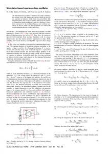
Fig. 2. The LC oscillator schematic and photograph of the chip.
thus achieving the desired temperature compensation effect for the oscillator. B. TC of Varactors for Temperature Compensation The frequency output of our -gm-LC oscillator, as shown in Fig. 2, can be deduced from the LC tank example in [7]
(1) where , and represents the varactor, inductor and the lossy resistor of the inductor, respectively; is the natural is the output osresonant frequency of the LC tank; and cillation frequency with consideration of the lossy . To determine the frequency drift of an oscillator, a deduction which includes the TCs of each component is impractical. Instead, the output frequency with consideration of temperature influences can be expressed using polynomials. First, we introduce an output frequency that is expressed as a function of the aggregate TCs of all components (excluding the varactor) as: (2) is defined at a referenced temperature and where is the first order TC. Note that only the first order TC is consid-
Using the proposed technique, the -gm-LC oscillator, as depicted in Fig. 2, was designed and fabricated. The on-chip 3.8-nH symmetrical chip-inductor was formed by merging the two inductors , as shown in the schematic. The varactor, , was designed using a PMOS transistor. The sizes of the PMOS transistors and and the NMOS transistors and are and , respectively. The varactors' bias voltage is obtained through a resistor divider using resistors of the same CMOS type. The proposed design was fabricated on a process. Excluding the bonding pads, the core circuit occupies an area of . The oscillator operates on a 1.4 V supply and consumes 10.9 mW of power (including buffers). III. MEASUREMENT RESULTS To verify the theoretical analysis and the technical merits of our proposed temperature compensation technique, the oscillator output was measured at different bias voltages (from to 1.8 V, in 0.1 V step increment) across a temperature range of to . The measured results are shown in the 3D graph in Fig. 3; the vertical axis represents the relative frequency change with respect to the referenced frequency at . By calculating the frequency derivation with respect to temperature at each voltage step in Fig. 3, it can be observed that the first order TC of the oscillation frequency shifts from negative to positive when bias voltage increases from to 1.8 V. This verifies that the TC characteristics of the varactor shifts from positive value to negative value with respect to a rising bias voltages as shown in Fig. 1. In Fig. 3, the plot exhibits a low fluctuation region (i.e., the green region with variation between 0 to 250 ppm) at around 0.2 V applied bias. This
132
IEEE MICROWAVE AND WIRELESS COMPONENTS LETTERS, VOL. 25, NO. 2, FEBRUARY 2015
TABLE I PERFORMANCE COMPARISON
Fig. 3. Measured frequency drift normalized with respect to that at different temperatures and varactor's bias voltages.
under
to the design using computer aided trimming technique in [7] and discrete resonator based oscillator in [10]. IV. CONCLUSION A temperature compensation technique using constant-biased varactors for LC oscillator is presented and the design has been successfully verified on a conventional CMOS technology. The proposed technique compensates the overall temperature characteristic of an oscillator through altering the TC of MOS varactors using a constant bias voltage. This approach reduces the compensation mismatches, thus improving the overall temperature accuracy. The fabricated 2.09 GHz-gm-LC oscillator yields a frequency inaccuracy over a temperature range of to , which outperforms the state-of-the-arts. This technique is beneficial for clock generation that demands precise accuracy and for applications across wide temperature ranges. REFERENCES
Fig. 4. (a) Measured oscillation frequencies from to at of 0.1 V, 0.2 V, and 0.3 V. (b) Output frequency temperature dependence of LC oscillator versus the varactors' applied bias voltage on four measured samples.
region gives the optimum performance in terms of temperature stability. The temperature sweep of the output frequency and the absolute frequency error plot for different bias voltages are plotted in Fig. 4. From the four measured samples in Fig. 4(b), the measured frequency inaccuracy is only when the varactor bias voltage is set at 0.2 V. Even for a relative large fluctuation of bias voltage ( about the reference 0.2 V), the . In addition, the osfrequency error is still less than cillator also has phase noise performance of and at 100 KHz and 1 MHz offsets, respectively. A performance summary of this temperature compensated LC oscillator is listed in Table I, with comparisons against the current state-of-the-arts. Using our proposed technique, the TC of the oscillation frequency is directly rectified towards zero through the constant-biased varactors, thus accurately reduces the frequency inaccuracy. Our demonstrated work achieved the lowest frequency inaccuracy among the state-of-the-arts [1]–[6] for the same temperature range. In fact, this work is comparable
[1] K. Sundaresan, P. E. Allen, and F. Ayazi, “Process and temperature compensation in a 7-MHz CMOS clock oscillator,” IEEE J. Solid-State Circuits, vol. 41, no. 2, pp. 433–442, Feb. 2006. [2] Y.-H. Chiang and S.-I. Liu, “Submicrowatt 1.1-MHz CMOS relaxation oscillator with temperature compensation,” IEEE Trans. Circuits Syst. II, vol. 60, no. 12, pp. 837–841, Dec. 2013. [3] X. Zhang and A. B. Apsel, “A low-power, process-and-temperaturecompensated ring oscillator with addition-based current source,” IEEE Trans. Circuits Syst. I, vol. 58, no. 5, pp. 868–878, May 2013. fully-integrated 6 MHz [4] V. D. Smedt et al., “A wienbridge oscillator with a 172 dB phase noise FOM,” IEEE J. SolidState Circuits, vol. 44, no. 7, pp. 1990–2001, Jul. 2009. 1-MHz relaxation [5] N. Sadeghi et al., “A in oscillator for high-temperature applications up to CMOS,” IEEE Trans. Circuits Syst. I, vol. 60, no. 7, pp. 1692–1701, Jul. 2013. voltage and temperature [6] V. D. Smedt et al., “A 0.6 V to 1.6 V, independent 48 MHz pulsed LC oscillator for RFID tags,” in IEEE Asia Solid-State Circuits Conf. Dig. Tech. Papers, Nov. 2011, pp. 109–112. [7] M. S. McCorquodale et al., “A monolithic and self-referenced RF LC clock generator compliant with USB 2.0,” IEEE J. Solide-State Circuits, vol. 42, no. 2, pp. 385–399, Feb. 2007. [8] H. H. Hu et al., “Temperature-dependent capacitance characteristics of RF LDMOS transistors with different layout structures,” IEEE Trans. Electron Device, vol. 29, no. 7, pp. 784–787, Jul. 2008. [9] S. M. Sze and K. K. Ng, Semiconductor Devices: Physics and Technology. New York: Wiley, 2012. [10] U. L. Rohde and A. K. Poddar, “Novel multi-coupled line resonators replace traditional ceramic resonators in oscillators/VCOs,” in Proc. IEEE Int. Freq. Control Symp. Expo., Jun. 5–7, 2006, pp. 432–442.