International Journal on Electrical Engineering and Informatics - Volume 10, Number 3, September 2018
Adaptive Neuro-Fuzzy Scheduled Load Frequency Controller for Multi Source Multi Area System Interconnected Via Parallel AC-DC Links K.R.M.Vijaya Chandrakala and S. Balamurugan Department of Electrical and Electronics Engineering, Amrita School of Engineering, Coimbatore, Amrita Vishwa Vidyapeetham, India.
[email protected] Abstract: The article focuses towards the development of an optimal secondary controller which could adapt with the varying system conditions to maintain the frequency and tieline power flow variations within the nominal value. For the analysis, a two area multi source system consisting of thermal, hydro and nuclear system in one area is interconnected with another area comprising of thermal and hydro system via parallel AC-DC links. On subjection to unit step load change in demand, the impact on frequency and tie-line power flow variations in multi source multi area is observed under MATLAB / Simulink environment. The fine tuning of frequency and tie-line power flow variations is achieved with the help of secondary controller. Optimal secondary Proportional Integral (PI) controller is chosen based on Zeigler Nichols’ (ZN), Genetic Algorithm (GA), Fuzzy Gain Scheduling (FGS) and Adaptive Neuro-Fuzzy Inference System (ANFIS) tuning techniques. On subjection to different load variations at different intervals of time, ANFIS tuned PI controller has retained the frequency and tie-line power variations for a robust multi source multi area system interconnected via parallel AC-DC links in a much faster way to its nominal values than other methods. The performance of the controller is evaluated based on performance indices. Keywords: Load Frequency Control (LFC), Zeigler Nichols’ (ZN) Method, Genetic Algorithm (GA) Technique, Adaptive Neuro-Fuzzy Gain Scheduling (ANFIS) Technique, Integral Squared Error (ISE).
1. Introduction In today’s era of fast developing loads when compared to utilities have paved way towards reliable power supply. In interconnected system due to vast variations in loads, the frequency variations and tie-line power flow to be in limits is a challenging task. Load Frequency Control (LFC) plays a major key role in keeping the system operation and control intact [1-3]. Many of the researchers have contributed their work towards LFC in inter-connected system [4-8]. When subjected to load change, a High Voltage Direct Current Transmission (HVDC) Line in anti-parallel with the High Voltage Alternating Current (HVAC) line [9-12] connecting two areas would result reduced area frequencies and tie-line power flow. In this work, for the analysis as a multi-source thermal, hydro and nuclear of one area is interconnected via HVAC and HVDC anti parallel tie-line with another area of hydro and thermal system. When load changes in an interconnected system comprising of multi sources, the frequency and tie-line power flow varies, as such, primary control loop governed by the speed governor sets the system back to its nominal value. Due to the limitations in droop change of the speed governor which relies between 2-3%, the system settles nearer to the nominal value with a steady state error. For settling the system back to its nominal state, secondary controller comes into action. As secondary controller, PI controller has achieved its par in control applications for its flexible operation. ZN method as a conventional benchmark is used for tuning the gains of the PI controller [13-15]. To achieve optimal gain values of PI controller GA, PSO (Particle Swarm Optimization), SA (Simulated Annealing) techniques are used by many researchers
Received: August 3rd, 2017. Accepted: September 27th, 2018 DOI: 10.15676/ijeei.2018.10.3.5 479
K.R.M.Vijaya Chandrakala, et al.
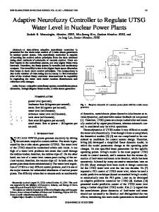
under load frequency control issues. In this work, GA technique [16-17] is used for tuning the gain values of the PI controller which provides global optimal values. But, ZN and GA tuned PI controller gain values being fixed; it fails to vary the gain values with the system varying conditions. Therefore, FGS based on its efficient decision making will help to vary the gain values of the controller with respect to varying system conditions. For effective gain scheduling to adapt with the system on wide varying conditions ANFIS [18-22] is used in this work. ANFIS considers the Fuzzy Inference System (FIS) to take the decision and further optimizes to adapt with the help of neural network to judge wide range of variations in the system and retains the system frequency and tie-line power flow in nominal values. The controller performance is evaluated based on performance indices [27-28]. For practicality, as a case study, multi source multi area system is included with reheat steam turbine, boiler dynamics with the limits bounds to turbine operation namely, Generation Rate Constraints (GRC) is considered to make the system highly robust in nature on a scale of wide varying characteristics of the system [23]. Instead of identical areas, the system is operated under nonidentical areas approach. ANFIS based PI controller is used for adapting the controller gains with respect to wide change on system conditions to bring back the system area frequencies and tie-line power flow to its normal value. The discussion of the work starts with the section 2 which states about the modelling of multi source multi area system with parallel AC-DC links, Section 3 deals with the tuning methods adopted for secondary PI controller, Section 4 discusses with simulation results and case study and finally section 5 concludes the work 2. Modeling of Multi Source Multi Area System Interconnected Via Parallel AC-DC Links For analysis, two similar areas interconnected via HVAC in anti-parallel with HVDC tieline operating at a capacity of 2000 MW with nominal load of 1000 MW operating at 50Hz is taken into consideration. An area comprises of non-reheat steam turbine, hydro turbine and nuclear turbine driving a generator connected to a load is interconnected to another area of hydro turbine and non-reheat steam turbine driving the generator and load. The one-line diagram of multi source multi area interconnected via parallel AC-DC tie-lines is shown in Figure 1. Governor Hydro
Thermal Governor
Inverter
Load 1
Nuclear
DC link
Area 1
AC link
Governor
Control line
Rectifier
Power line
Governor Hydro
Thermal
Load 2
Governor
Area 2
Figure 1. One-line diagram of multi source multi area interconnected via parallel AC-DC links
480
Adaptive Neuro-Fuzzy Scheduled Load Frequency Controller for Multi
In thermal power plant [1-4], the turbine acts as the prime mover for the generator. The turbine gets the mechanical energy through steam from boiler. As demand increases, the difference between the generation and demand is indirectly sensed as change in frequency by the governor. The output of the speed governor is modeled as shown in Equation (1). (1) Depending on the sensed frequency value, the speed governor with the help of hydraulic amplifier alters the inlet valve position of steam, which in turn controls the frequency. The turbine output power w.r.t speed governor output and the generator output which provides the power to the power system is represented as shown in Equation (2) and Equation (3) respectively; (2) (3) The characteristics of hydro turbines are different from thermal turbines. In hydro plants [4], water is the source for producing mechanical energy to drive the turbine. Though it takes less time to start up, greater time lag prevails in the response during normal operation due to large water inertia. The linearized model representing the performance of the speed governor is highlighted in equation (4); (4) The output of the hydro turbine w.r.t. speed governor output is represented in Equation (5); (5) In nuclear power plant, the reactor core would contain 75 tons of uranium to produce an output of 1000 MW. In the reactor core the U-235 isotope fissions or splits, producing a lot of heat in a continuous process as a chain reaction. The process is fully controlled depending upon the presence of a moderator i.e. either water or graphite. The transfer function of nuclear speed governor is represented in Equation (6); (6) The water in its primary cooling/heat transfer circuit is pressurized water reactor (PWR) which generates steam to drive the generator to meet the demand. The turbine model of tandem-compound type which has one High Pressure (HP) and two Lower Pressure (LP) section with High Pressure (HP) re-heater sections [6]. High pressure steam surpasses through the reheat the HP exhaust. Before entering the LP turbine the HP turbine exhausts MoistureSeparator-Reheater (MSR). This helps to reduce the moisture of the steam and erosion rates while passing through LP section of the turbine. The transfer function of LP and HP turbine respectively is represented in Equation (7) and Equation (8) respectively. (7) (8) The generator is driven by power output of the turbine which generates electrical power to the power system is represented in equation (3). The tie-line interconnecting the two areas via HVAC and HVDC tie-line is modelled and written in transfer function as shown in equation (9) and equation (10) respectively. (9) (10) The tie-line power flow includes the variation on HVAC and as well as on HVDC tie-line. The mathematical modeling with the governing equations explained above for the GovernorTurbine system of Thermal, Hydro and Nuclear plant of an area interconnected via AC-DC links to an another area of Hydro and Thermal Power Plant is shown in Figure 2. The
481
K.R.M.Vijaya Chandrakala, et al.
limitation of the primary speed governor action to 2-3% would not help the system to retain to its normal value on subjection to unit step load change in area 1. Therefore, secondary controller is required for flexible operation. In this work, PI controller [13-14] is used for fine tuning of frequency and tie-line power flow variations to bring the system to its normal value. The transfer function of PI controller is shown in Equation (11), (11) The secondary controller is connected to the multi source multi area system as shown in Figure 2. The various tuning methods for optimal choosing of controller gains are discussed below. 1 R1 Pref 1 Secondary Controller
+
+ +
-
Pg
PH 1 1 + sTH 1
K1 1 + sT1
+-
Pref 2
1 + sTR 1 + sT2
Hydro Speed Governor
1 1 + sTNR
+-
pf11
PHV
PHT
+
1 − sTW 1 + 0.5sTW
pf12
PD1
Hydro Turbine
pf13
LP Nuclear-Turbine
1 + sTRH 2 (1 + sTRH 3 )(1 + sTN 2 ) LP Nuclear-Turbine
A12
Pref 4 Secondary Controller
+ +
B2
+
1 R2
Secondary Controller
+
Pref 5
PHg
-
Speed Governor
K1 1 + sT1
PHV PHT A 12 1 + sTR 1 − sTW 1 + sT2 1 + 0.5sTW pf21
Hydro Speed Governor
Pg
-
Power System
PACtie12
1 R3
1 1 + sTH 1
PH
Hydraulic Amplifier
Hydro Turbine
1 1 + sTT 1
PT
Non – Reheat Turbine
f1
K P1 1 + sTP1
NT
K RN 1 (1 + sTN 1 )(1 + sTRH 1 )
K P1 1 + sTP1
+ + -
K HN 1 HP Nuclear- Turbine 1 + sTN 1 P
∆P Speed Governor NR
Pref 3 Secondary Controller
1 R2
PHg
PT
Non – Reheat Turbine
Speed Governor Hydraulic Amplifier Secondary Controller
1 1 + sTT 1
PDCtie12
B1
pf22
PD 2
2 T s
+ -
A12
+ + -
Power System
K P2 1 + sTP 2
f 2
1 R1
Figure 2. Linearized mathematical model of multi source multi area interconnected via parallel AC-DC links 3. Secondary Controller Tuning Methods The secondary controller helps to support the power system along with the primary controller thus removing the frequency and tie-line power offset namely the steady state error which is not advisable for the system to persist. But, since the condition of the system is subjected to dynamic load variations at various intervals of time, a dynamic secondary controller (PI) is proposed in this work. Therefore, suitable secondary controller optimal values is identified by various methodologies which is proposed in the following sections.
482
Adaptive Neuro-Fuzzy Scheduled Load Frequency Controller for Multi
A. Zeigler Nichols’(ZN) Tuning Method As a conventional bench mark, ZN method [13-15] is used for choosing the better value of controller gains. In this method, proportional gain ‘Kp’ is increased maintaining integral gain ‘Ki’ to zero. The gain at the system oscillates is termed to be ultimate gain ‘Ku’ and the difference between the peak for one cycle is termed to be ultimate time ‘Tu’ is observed. The PI controller gains computed using Zeigler Nichols’ method are 6.995 and 1.034 respectively in area 1 and area 2. B. Genetic Algorithm (GA) Tuning Method ZN tuned PI controller gain values are not the optimal one. Therefore, optimization techniques are adopted for obtaining optimal values of PI controller for the multi source multi area system interconnected via parallel AC-DC links. In this work, GA technique [16-17] is used for tuning the PI controller. The algorithm adopted for tuning PI controller gains is as follows: Step 1: Estimate ranges for the proportional and integral gains Step 2: Randomly initialize the values for the controller gains Step 3: On subjection to unit step load change in area 1; evaluate the objective function to minimize the integral squared error of area frequencies and tie-line power flow change on subjection to unit step load change in area 1 Step 4: Is the convergence criteria of error minimization is met? If No, apply genetic operator by creating new ranges for the controller gains through reproduction, crossover and mutation and go to step3 and repeat the process. Step 5: If Yes, stop. PI controller gain values obtained are the optimal values to be considered in the plant. The optimal gain values of the PI controller using GA technique are tabulated in Table 1. Table 1. GA tuned PI controller gain values
Multi source multi area hydro thermal interconnected with parallel AC-DC links
system
Area 1
Area 2
Kp1
1.0002
Ki1
4.2896
Kp2
2.7915
Ki2
5.3155
Kp3
4.5830
Ki3
6.3600
Kp1
1.2173
Ki1
5.0275
Kp2
2.91001
Ki2
4.7160
C. Fuzzy Gain Scheduling (FGS) Tuning Method The optimal values chosen by GA method also provide fixed gain values which don’t change w.r.t varying system conditions. Therefore, FGS method [18-20], being much flexible and its decision making based on varying system conditions is considered in this work. The functional diagram of FGS in making the decision is shown in Figure 3.
483
K.R.M.Vijaya Chandrakala, et al.
Fuzzy Gain Scheduling Data Base
f1 (s)
du dt
Fuzzification
Knowledge Base
Defuzzication
Rule Base
Kp +
+
ACE
Ptie12 (s)
Ki s
PI controller
Pref 1(s)
Power plant (Area 1/Area 2)
f1 (s)
Figure 3. Schematic diagram of Fuzzy Gain Scheduling of PI controller
ACE1
In this work, FGS has two inputs namely change in error ACE and rate of change in error (du/dt). ACE or ACE1. The FGS based on the knowledge changes the reference power setting of the governor ∆Pref1(s). The two inputs and output are characterized with seven linguistic variable namely Negative Big (NB), Negative Medium (NM), Negative Small (NS), Zero (Z), Positive Small (PS), Positive Medium (PM), Positive Big (PB). The NB and PB are of trapezoidal membership function to accommodate the error lying in the infinity region. All other membership function is of triangular type. The input ACE range is between [-0.0171 0.0171] and the other input (du/dt). ACE or ACE1 range is between [-0.0283 0.0283], output range ∆Pref1(s) is between [-0.005 0.005]. The rules are framed in such a way that it suits for both Kp and Ki which is furnished in Table 2. Table 2. Fuzzy rules for scheduling Kp and Ki ACE LN MN SN Z SP MP LN LP LP LP MP MP SP MN LP MP MP MP SP Z SN LP MP SP SP Z SN Z MP MP SP Z SN MN SP MP SP Z SN SN MN MP SP Z SN MN MN MN LP Z SN MN MN LN LN
LP Z SN MN MN LN LN LN
The rules are of IF AND THEN type. For example; If ACE is LN and ACE1 is LN then output is LP. D. Gain Scheduling using Adaptive Neuro-Fuzzy Inference System The fuzzy system helps in to change the controller gains under varying system conditions and neural network proven its relevance in adapting towards the system conditions. Depending on wide variations of the system conditions, FGS fails to provide control on the system which could be overruled by ANFIS [22-23]. The efficient decision making by the FIS correlated with the adaptive neural network would help to handle the system being highly robust. The functional diagram of ANFIS is shown in Figure 4. Based on the prior knowledge, FGS has scheduled the PI controller gains for the multi source multi area system subjected to load variations by reduced optimization search space. With this Neural network adapts by applying back propagation to the structured network to automate FIS parametric controller tuning.
484
Adaptive Neuro-Fuzzy Scheduled Load Frequency Controller for Multi
ANFIS based Gain Scheduling
f1 ( s )
Data Base
du dt
− +
Fuzzification
Artificial Neural Network
Knowledge Base
Defuzzication
Rule Base
Kp + ACE
Ki s
PI controller
Robust power plant (Area 1/Area 2)
f1(s)
Pref 1(s)
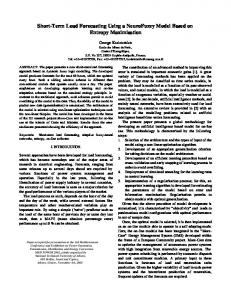
Ptie12 (s) Figure 4. Schematic diagram of ANFIS based Gain Scheduling of PI controller The ANFIS algorithm is explained as follows: Step 1: Load the training data obtained by the Fuzzy Inference System (FIS) comprising of two inputs and one output. Step 2: Set the input parameter of membership function and generate the ANFIS model. Step 3: If the error minimized or converged? If Yes, get optimized FIS after training which would be adaptable gain values of the PI controller. Step 4: If No, go to step 2 and proceed until converged. The controller performance is evaluated based on Integral Squared Error (ISE) [27-28] which is represented in equation 12. (12) 4. Results and Discussions As discussed in Section 2, Figure 2 model of multi source multi area system with parallel AC-DC links is developed using MATLAB/ Simulink [24] without secondary controller. The system with parallel AC-DC links is subjected to unit step load disturbance in area 1 and its frequency and tie-line power flow variations is observed and compared without HVDC line. The comparison response with and without HVDC tie-line is shown in Figure 5.
Figure 5. Response of multi source multi area interconnected via parallel AC-DC Links and with only AC link
485
K.R.M.Vijaya Chandrakala, et al.
From the above Figure, it clearly shows that with two-area interconnected via parallel ACDC links and without HVDC tie-line on subjection to unit step load disturbance in area 1 has led to area frequency variations and tie-line power flow with reduced steady state error. Therefore, preferably with a parallel AC-DC link interconnecting areas would help in limiting the variations in area frequencies and tie-line power flow on load variations.
Figure 6. Comparison response of primary loop, ZN and GA tuned PI controller of multi source multi area interconnected via parallel AC-DC links
Figure 7. Comparison response of GA, FGS and ANFIS tuned PI controller of multi source multi area interconnected with parallel AC-DC links As discussed in section 3, due to the limitation in speed governor characteristics, PI controller would help the system to retain to its nominal value by fine tuning the variations. Therefore, as discussed in section 3.1 with gain values as highlighted and section 3.2 with GA method, the gain values as highlighted in Table 1 is included in multi source multi area system interconnected via parallel AC-DC links without the secondary controller is shown in Figure 6.
486
Adaptive Neuro-Fuzzy Scheduled Load Frequency Controller for Multi
From the comparison response referring to Figure 6, with secondary controller GA technique has given optimal PI controller gain values when compared to ZN tuned and without secondary controller. But, using GA technique PI controller gain values are fixed and doesn’t changes w.r.t system conditions. Therefore, FGS is used for scheduling the gain values as discussed in section 3.3 and adapting the system w.r.t to increase in robustness of the system ANFIS as discussed in section 3.4 is incorporated in the system. The comparison response of ANFIS with FGS and GA technique tuned PI controller is shown in Figure 7. From the above Figure, it is quite evident that ANFIS based PI controller has reduced subsequently the variations in frequency and tie-line power flow with reduced peak overshoot and faster settling time to its nominal value when subjected to 1% load change in area 1. The performance indices evaluated based on ISE is shown in Table 3 which helps in judging the controller performance and proves ANFIS as suitable PI controller which helps in fine tuning the variations. Table 3. Performance and percentage improvement of various controllers in multi source multi area hydro thermal system based on ISE Secondary Controller ISE ZN tuned PI 0.0001077 GA tuned PI 9.715e-5 FGS 7.25e-5 ANFIS 2.22e-5 % Improvement GA (PI) w.r.t ZN (PI) 9.79 FGS (PI) w.r.t GA (PI) 25.37 ANFIS (PI) w.r.t FGS (PI) 69.3
Figure 8. Response of ANFIS tuned PI controller of multi source multi area with parallel ACDC links under non-linearities From the Table 3, based on ISE and improvement in percentage comparison among the controllers, ANFIS tuned PI controller proves to be the suitable optimal secondary controller which helps in fine tuning of frequency and tie-line power flow and thus helps in retaining the values to its nominal value than other controllers. The performance of the ANFIS based PI controller is tested under robust system by including the boiler dynamics, reheat steam turbine [1-3, 30] in thermal power plant in both the areas, on subjection to increase and decrease of 1%
487
K.R.M.Vijaya Chandrakala, et al.
load change during 0sec, 80sec and 160 sec in area 1 and area 2 operating at decrease and increase of 1% load change during 40sec and 120sec respectively. Instead of identical power system, area1 operating at a capacity of 800 MW and area 2 operating at a capacity of 1250MW. The system is simulated using MATLAB/Simulink, and the response of robust multi source multi area system interconnected via parallel AC-DC links with ANFIS based PI controller is shown in Figure 8. From the above Figure, it clearly visualizes that ANFIS based PI controller is the best optimal adaptive controller for a robust multi source multi area system interconnected via parallel AC-DC links which improved the area frequencies and tie-line power flow variations. 5. Conclusion In this study, multi source multi area system interconnected via parallel AC-DC links is considered. The system was subjected to unit step load variations in area 1 alone. The limitation on speed governor characteristics would help system to retain to its nominal value but with area frequencies and tie-line power flow error. Therefore, PI controller was tuned using ZN, GA, FGS and ANFIS techniques were used. The controller performance was justified through ISE and judged that ANFIS based PI controller is the most optimal and best secondary controller which would adapt with the wide varying system conditions and helped in handling robust system thus retaining the system frequency and tie-line power flow variations within the rated value. Appendix Thermal Plant: R1 =Speed regulation of thermal governor = 2 Hz/p.u. MW;
TH 1 = Turbo governor time constant = 0.08 sec; TT 1 =Non-reheat turbine time constant = 0.3 sec; 1 = 2 = Frequency bias constant of area1and area2 = 0.425 p.u.MW/Hz; Hydro Power Plant: R2 =Speed regulation of hydro governor =2 Hz/p.u. MW;
T1 = Hydro governor time constant = 48.7 sec; TR , T2 = Hydro power plant time constants = 5.0 sec, 0.513 sec; TW = Water time constant = 1.0 sec; Nuclear Power Plant: K HN 1 =HP nuclear turbine gain = 0.2-2.0;
TN 1 =HP nuclear turbine time constant = 0.5 sec; K RN 1 =LP nuclear two stage turbine gain = 0.3; TRH1 = LP nuclear two stage turbine time constant = 7sec; TRH 2 = TRH 3 = LP nuclear two stage turbine time constant = 6sec and 10sec respectively; TN 2 = LP nuclear two stage turbine time constant = 9sec; DC Link: PDCtie12 = Change in the HVDC tie-line power flow in p.u.;
K DC = HVDC tie-line gain = 1.0; TDC = HVDC tie-line time constant = 0.2sec; AC Link:
488
Adaptive Neuro-Fuzzy Scheduled Load Frequency Controller for Multi
PACtie12 = Change in the HVAC tie-line power flow in p.u.; A12 =Synchronizing power co-efficient = -1; 6. References [1]. Fosha C. & Elgerd O.I., “The megawatt- frequency control problem: a new approach via optimal control theory”, IEEE Transactions on Power Apparatus and Systems, Vol.PAS-89, No.4, pp.563-577, 1970. [2]. Elgerd O.I., “Electric Energy Systems Theory an Introduction”, Tata McGraw Hill Edition, 1983. [3]. Kundur P., “Power System Stability and Control”, McGraw Hill Inc., Newyork, 1994. [4]. IEEE PES Committee Report, “Dynamic Models for Steam and Hydro Turbines in Power System Studies”, IEEE Transactions on Power Apparatus and Systems, Vol.PAS- 92, 1973. [5]. Selva Kumar, S., R. Joseph Xavier, and S. Balamurugan. "Small signal modelling of gas turbine plant for load frequency control", 2016 Biennial International Conference on Power and Energy Systems Towards Sustainable Energy (PESTSE), 2016 [6]. Ichikawa T., “Dynamics of Nuclear Power Plant in Electric Power System (Part 1)- BWR plant”, CRIEPI Report No.175079, 1976. [7]. Sateesh Kumar Vavilala, Srinivas R.S. & Machavarapu Suma, “Load frequency control of two area interconnected power system using conventional and intelligent controllers”, Int. Journal of Engineering Research and Applications, Vol.4, No.1, pp.156-160, 2014. [8]. Singh Parmar K.P., Majhi S. & Kothari D.P., "Load frequency control of a realistic power system with multi-source power generation. Electrical Power and Energy Systems”, Vol.42, pp.426-433, 2012. [9]. Mathur H. D. & Manjunath, H. V., “Study of Dynamic Performance of Thermal Units With Asynchronous Tie-Lines Using Fuzzy Based Controller”, Journal of Electrical Systems, Vol. 3, No. 3, pp.124-130, 2007. [10]. Shashi Kant Pandey R., Soumya Mohanty and Nand Kishor, “A Literature Survey on Load-Frequency Control for Conventional and Distribution Generation Power Systems”, Renewable and Sustainable Energy Reviews, Vol.25, pp.318-334, 2013. [11]. K.R.M. Vijaya Chandrakala, S. Balamurugan, "Simulated annealing based optimal frequency and terminal voltage control of multi source multi area system", International Journal of Electrical Power & Energy Systems, Vol.78, pp.823-329, 2016. [12]. Chandrakala, Vijaya, Balamurugan Sukumar, and Krishnamoorthy Sankaranarayanan. "Load Frequency Control of Multi-source Multi-area Hydro Thermal System Using Flexible Alternating Current Transmission System Devices", Electric Power Components and Systems, Vol.42, No.9, pp. 927-934, 2014. [13]. W. Tan, “Tuning of PID load frequency controller for power systems. Energy Conversion Management”, Vol.50, No.6, pp.1465-1472, 2009. [14]. J. G. Ziegler & N. B. Nichols, “Optimum Setting for Automatic Controllers”, Transactions of ASME, Vol. 64, pp.759-768, 1942. [15]. George Stephanopoulos, “Chemical Process Control”, Prentice Hall of India, 1984. [16]. S.P. Ghoshal, “GA-fuzzy based fast acting adaptive active power-frequency control of interconnected multiple thermal generating areas”, IE (I) Journal— EL, Vol. 85,pp.209215, 2005. [17]. F. Daneshfar, H. Bevrani, “Load frequency control: A GA-based multi-agent reinforcement learning”, IEE Proceedings - Generation, Transmission and Distribution, Vol.4, No.1, pp.13-26, 2010. [18]. Du Xiuxia, Li Pingkang, “Fuzzy logic control optimal realization using GA for multiarea AGC systems”, International Journal of Information Technology, Vol.12, No.7, pp.63-72, 2006.
489
K.R.M.Vijaya Chandrakala, et al.
[19]. S.P. Ghoshal, “Multi-area frequency and tie-line power flow control with fuzzy logic based integral gain scheduling”, IE(I) Journal—EL, Vol.84, pp.135-141, 2003. [20]. Ertugrul cam and Kocaarslan I., “Load frequency control in two area power systems using fuzzy logic controller”, Energy Conversion and Management, Vol.46, pp.233243, 2005. [21]. Kalyan Chatterjee, “PI Controller for Automatic Generation Control Based on Performance Indices”, World Academy of Science, Engineering and Technology, Vol.0051, pp.321-328, 2011. [22]. Rahmani M. & Sadati, N., “Hierarchical Optimal Robust Load-Frequency Control for Power Systems”, IET Generation, Transmission and Distribution, Vol. 6, pp.303-312, 2012. [23]. Tsay Tain-Sou, “Load-frequency control of interconnected power system with governor backlash nonlinearities”, Electrical Power and Energy Systems, Vol. 33, pp.1542, 2011. [24]. MATLAB User Manuals, Mathworks Inc. U.S.A, 2000.
K.R.M. Vijaya Chandrakala obtained her Ph.D., in power system control from Anna University, Chennai, India. Currently, she is working at Amrita School of Engineering, Amrita Vishwa Vidyapeetham, Ettimadai, Coimbatore, India in EEE Department as Assistant Professor (Selection Grade). Her area of interest is Load Frequency Control, Renewable Energy integration to Smart Grid, Electric Vehicle Applications, Soft Computing Techniques.
S. Balamurugan has been awarded with Ph. D. from Anna University, Chennai, India. He is currently serving as Associate Professor in the Department of Electrical and Electronics Engineering at Amrita School of Engineering, Coimbatore, India. His area of interest are Power System, Energy Management, Deregulated System, Smart Grid, Artificial Neural Networks, Fuzzy Logic, Genetic Algorithm.
490