Without Load and Filter Current Measurement. Engin Ozdemir. Mehmet Ucar. Metin Kesler. Murat Kale. Kocaeli University. Kocaeli University. Kocaeli University.
source back-to-back power converters, wind turbine system with permanent ... (ST-DTC) [4], [5] for machine side, and direct power control. (ST-DPC) for grid side), ... Z. Zhang and R. Kennel are with the Institute for Electrical Drive. Systems and ..
Sep 14, 2004 - series active compensators used in power quality ... compensate for the main types of disturbances in electrical power systems, is considered.
With increasing penetration level of WTs into the grid, the wind. Manuscript received December 15, 2010; revised May 05, 2011 and July. 27, 2011; accepted ...
An Advanced Tuning Methodology for Fuzzy Control : With Application to a Vacuum Cleaner. M. Kemal Ciliz. Electrical and Electronics Engineering Department.
Advanced access control system for ports. Fabio Garzia1,2, Roberto Cusani1. 1Department of Information, Electronics and. Telecommunication Engineering.
IEEE EUROCON 2017, 6â8 JULY 2017, OHRID, R. MACEDONIA. The velocity value is calculated according to how far an individual's data is from the target.
1. The main idea behind the -EM algorithm is to search for an effective surrogate function or a minorizer for the maximization of the observed data's likelihood ...
Jun 12, 2013 - Neil Sinclair, Student Member, IEEE, David Harle, Member, IEEE, Ian A. Glover, ... N. Sinclair, D. Harle, J. Irvine, and R. C. Atkinson are with the ...
(MPPT) of the PV output for all sunshine conditions is a key to keep the output power per unit cost low for successful PV applications. This paper proposes a.
Welding and NDT Research Center/Image and Signal Processing Laboratory, Cheraga, Algeria ... algorithm for radiographic image segmentation, based on.
Queen Mary University of London. London, UK john.bigham, [email protected]. Abstractâ Recent developments in mobile networks have looked.
In this study, a down scaling algorithm to disaggregate the radiometer Brightness Temperature (TB) using the radar backscatter observations for SMAP (Soil ...
Jan 8, 2016 - CRS interference cancellation algorithm for heterogeneous network. H. Luo. â. , W. Li, Y. Zhang, L.-K. Huang, J. Cosmas and Q. Ni.
conventional PAM modulation with an orthogonal channel taken from a CAP system. ... offer the potential to achieve high-speed transmission despite bandwidth.
Dec 1, 2008 - DECEMBER 2008 â¡ IEEE INDUSTRIAL ELECTRONICS MAGAZINE 1. Book News. Industrial Control Technology. A. Handbook for Engineers.
Abstract— This paper proposes a computationally efficient method for supervisory control of Volt/Var control devices- voltage regulators and capacitor banks –on ...
HE VITERBI algorithm (VA) was proposed in 1967 as a method of decoding convolutional codes. Since that time, it has been
Abstract. Modular Multilevel Converters (MMC) are becoming increasingly popular with the development of. HVDC connection and, in the future, Multi Terminal ...
AbstractâDistributed Generation (DG) is used widely in the modern distribution systems. This paper proposes a novel func- tionality of the interface between DG ...
Index Terms--IPM synchronous motor; ac motor drives; direct torque control; field-weakening; system stability. I. INTRODUCTION. In modern electric drives, ...
Sep 28, 2014 - College of Engineering and Science. Victoria University. Melbourne, Australia. [email protected]. AbstractâProportional and Integral (PI) ...
themes: i) modeling and stability analysis; and ii) advanced con- trol and design. A brief discussion of .... Southern California Edison. Rosemead, CA 91770 USA.
Advanced ANFIS-MPPT Control Algorithm for Sunshine ... - IEEE Xplore
Advanced ANFIS-MPPT Control Algorithm for Sunshine. Photovoltaic Pumping Systems. Farhat Mayssa1, Lassâad Sbita2. 1, 2. Research Unit of Photvoltaic, ...
2012 First International Conference on Renewable Energies and Vehicular Technology
Advanced ANFIS-MPPT Control Algorithm for Sunshine Photovoltaic Pumping Systems Farhat Mayssa1, Lassâad Sbita2 1, 2
Research Unit of Photvoltaic, Wind and Geothermal systems, National Engineering school of Gabès, Electrical and Automation Department, University of Gabes, Tunisia, e-mail: [email protected]
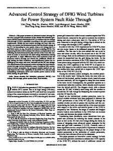
ABSTRACT Recently, the solar energy has become an alternative source of energy of great importance. Divers researches and efforts have been concentrated on the photovoltaic (PV) systems efficiency improvement and the accessibility to this technology. This paper presents an intelligent approach for the improvement and optimization of the PV system efficiency. A PV system topology incorporating maximum power point tracking controller (MPPT) is studied. In order to perform this goal a special interest was focused on the neuro–fuzzy algorithm based on the Sugeno inference model. This paper presents a detailed study and design of a MPPT controller to insure a high PV system performance which can be selected for practical implementation issue. A simulation work dealing with MPPT controller, a DC/DC CùK converter feeding a DC moto-pump is achieved. Significant extracted results are given to prove the validity of the proposed overall PV pumping system. Index Terms— PV, MPPT, ANFIS, CùK, DC motor and pump In general, The MPPT control presents a challenging, because the sunshine condition that determines the amount of sun energy into the PVG may change at any time. The current voltage characteristic of PVG is highly nonlinear [1]. In general a PV pumping system is typically built around the following main components as shown in figure 1: 1) A PVG that converts solar energy to electric one, 2) A DC-DC converter that manipulates produced DC voltage by the PV arrays to a load voltage demand, 3) A digital controller that drives the converter operation with MPPT capability. 4) A DC moto-pump.
Figure 1. Synoptic diagram of the proposed pumping system Since the PV array has a highly nonlinear characteristic, and its performance changes with operating conditions such as insulation or ambient temperature. 167
temperature is shown in figure 3. It is clear to find the three specific operating points.
Hence, it is technically challenging to develop a PV system that can overcome actual drawbacks.
(a) 10
In this paper the main contribution is to bring up a solution yielding to a high performances PV system.
I SC
9
G = 1000 W/m²
8 G= 80 0W/m²
Current (A)
7
2. MODELING OF PHOTOVOLTAIC SYSTEM
6 G = 600W/m²
5 4
G= 400 W/m²
3
2.1. PV Generator Model
current Zone
2
Pmax
1 0
VSC
Voltage Zone 0
5
10
15
20
25
30
35
40
Voltage(V) (b) 10 9 8 7
Current(A)
Figure2. Simplified PV Cell Equivalent Circuit One can substitute PV cell by equivalent electric circuit which included a power supply and a diode. The power produces the current Iph which depends on impinging irradiation. Through diode flows the current Id. The current ic feeding the load is the difference between Iph and Id which is reduced by the resistance RS. This last represents resistance of cell and connection among cells [2], [3]. The current Iph can be done by:
G I sc _ ref + K SCT (Tc − Tc _ ref G ref And the cell current is I ph =
(
))
⎛ ⎞ (V + R I ) q Ic = I ph − Irs ⎜ exp( (Vc + Rs Ic ) −1⎟ − c s c n T Rp β c ⎝ ⎠ With Irs reverse saturation current is:
(1)
(2)
3
⎡ qEg ⎛ 1 ⎛ T ⎞ 1 ⎞⎤ Irs = Irs _ ref ⎜ c ⎟ exp ⎢ − (3) ⎜ ⎟⎥ ⎜T ⎟ ⎢⎣ nβ ⎜⎝ Tc Tc _ ref ⎟⎠⎥⎦ ⎝ c _ ref ⎠ The modeling of a PV Array depending on Ns and ⎧I p = N p Ic ⎪ ⎪V p = ns N sVc ⎪ nN Np is then deduced as [4]: ⎪⎨ Rs = s s Rs Np ⎪ ⎪ nN ⎪Rp = s s Rp Np ⎪⎩ (4) Finally the Ip panel current can be given by
T=0C
6
T=25C
5 4
T=50C
3 2
T=75C
1 0
0
5
10
15
20
25
30
35
40
45
50
Voltage (V)
Figure 3. PVG Simulated I-V curves Module influenced by irradiation when the cell temperature is constant 25°C, (b) when irradiation is constant 1000W/m² First, the voltage zone which characterized by the open circuit voltage VOC, second, the current zone which characterized by the short – circuit current ISC, and finally the maximum power Zone, with Pmax. It is necessary to operate the PV at the third zone to extract the maximum power from the PVG. 2. 2. Cuk converter This converter type converts a continuous tension into another continuous one of reverses polarity, weaker or larger. Unlike other DC converter types, which use an inductance, a Cùk converter uses a condenser to store energy. The Cùk converter takes the name of its inventor, Slobodan Cùk, which was the first to describe this topology in an article [5]. This converter consists of two inductances, two condensers, a switch (generally a transistor) and of a diode. The basic diagram is represented figure 4.
⎛ q ⎛ Vp Rs IP ⎞ ⎞ Np ⎛ Vp Rs IP ⎞ (5) I p = Np I ph − Np Irs ⎜exp + + ⎜ ⎟ −1⎟ − ⎜ ⎟ ⎜ nβTc ⎜ ns Ns Np ⎟ ⎟ Rp ⎜ ns Ns Np ⎟ ⎝ ⎠ ⎠ ⎝ ⎠ ⎝
Figure 4. Circuit diagram of the CùK converter
The cartelistic I-V in various irradiation and 168
In steady state, output voltage of the CùK converter may be given by [6]: 1− D ⎧ Ia ⎪ I = D ⎪ s ⎨ V D ⎪ a = ⎪⎩ V s 1− D
power P and the water column ‘h’ [10].
(6)
⎧ a (h) = a0 + a1h1 + a2 h 2 + a3 h3 ⎪ 1 2 3 ⎪b(h) = b0 + b1h + b2 h + b3 h ⎨ 1 2 3 ⎪c(h) = c0 + c1h + c2 h + c3 h ⎪ d (h) = d + d h1 + d h 2 + d h 3 ⎩ 0 1 2 3
The converter model in a state space representation is as follows:
Figure 5 shows the characteristics of the power according to the flow rate (P=f (Q)). They are dressed according to various heights of the water columns as given by equations 10 and 11. 700
h=5m h=10m h=15m h=20m h=25m h=30m
600
500
0
;
⎡1⎤ ⎢L ⎥ ⎢ 1⎥ B=⎢0⎥ ⎢ ⎥ ⎢0⎥ ⎢⎣ 0 ⎥⎦
Power (W)
With:
(7)
(10)
P ( Q , h ) = a ( h ) Q 3 + b ( h )Q 2 + c ( h )Q + d ( h )
400
300
200
100
0 0.2
0.25
0.3
0.35
0.4
0.45
0.5
0.55
0.6
0.65
0.7
3
Q(m /h)
Figure 5. Pump characteristic. From figure 5 it is easily to deduce that for a water height of 20 m, eq. 12 yields to the pumped water flow rate [11].
2.3.DC Moto-pump The dynamic model of a DC motor is [7], [8]. di a ⎧ ⎪⎪ L a d t = U a − R a i a − K t ω ⎨ ⎪ j dω = T −T − f ω em l ⎪⎩ d t
Flow =
(8)
Recently, the photovoltaic pumps drew a considerable attention. The flow of water in pumps with positive displacement is a function of the shaft speed. A piston pump working principle is to use the variations of volume caused by the piston displacement in a cavity. These displacements alternatively in a direction or in another, produce an aspiration or repression phases. When the piston moves in a direction the liquid is compressed: there are closing of the induction valve and opening of the repression valve. Operation is reversed at a time of fluid aspiration in the pump. This type of pump has the advantage of dry operation. Nevertheless, the flow is limited; viscosity is rather low and the pumping of solid particles impossible. The model of the positive displacement pump load torque with is [9]. TL = C1 ⋅ ω + C2 (9) In this context one proposes a mathematical model which directly connects the pump water flow rate to the
0, 6 P 220
(12)
3. AN ADAPTIVE NEURO-FUZZY INFERENCE SCHEME Neuro-fuzzy technique is referring to the way of applying various learning methods available in the neural network literature to a fuzzy inference system (FIS) [12], [13], [14]. The main structure of a FIS consists of three major components: a rule base one, which deals with fuzzy rules selection [15], a database concept, which defines the fuzzy rules membership functions (MF) and a decision engine, which bring up the inference procedure to depict an output The fuzzy logic concepts are based on expert knowledge whereas the neural network models are built around a data base. Moreover, neuro-fuzzy approach seems to be suitable if both data and knowledge sources of the used system are available. Here, the neuro-fuzzy controller is the so called adaptive network which based on fuzzy inference system (ANFIS). The system structure is an adaptive network running as a first-order Sugeno fuzzy inference system. The ANFIS learning rule is a hybrid one which combining backpropagation, gradient-descent in one hand and a least-squares 169
algorithm to identify and optimize the Sugeno first order system on the other hand. To explain the ANFIS working process, an equivalent ANFIS architecture with two rules is illustrated in Figure 6 [13], [16]. The given architecture has five layers and every node in a layer has a similar function. The two fuzzy rules, in which outputs are dressed as linear combinations of their inputs, are: Rule1: if x is A1 and y is B1 then f1:=p1x+q1x+r1 Rule2: if x is A2 and y is B2 then f2:=p2x+q2x+r2
(13) (14)
x y w1
A1
A1
N
Π
x A2
Σ
f
B1 y
A1
N
Π B2
w2
and (pi, qi, ri) is the consequent parameter set of the node.
Layer 5: in the single node, labeled Σ, calculates the overall ANFIS output from the sum of the node inputs: ∑ i wi fi (19) ο 5 ,i = ∑ w i f i = i ∑ i wi The ANFIS controller developed in this section includes ' Ip ' and ' P ' as inputs and 'D’ as output which represent respectively, the PV current, the PV-Power and the converter duty cycle ratio. The input variables allow the ANFIS to generate the converter command. This last is applied to the converter, in order to ensure the adaptation of the power provided by PVG. This controller yields to an automatic fuzzy rules generation based on the Sugeno inference model. The equivalent neural structure of the proposed ANFIS is given by figure 7.
x y Layer 1
Layer 2
Layer 3
Layer 4
Layer 5
Figure 6. Architecture of The ANFIS model Sugeno’s fuzzy inference method
Layer 1: consists of adaptive nodes that generate membership grades of linguistic labels based upon premise signals, using any appropriate parameterized membership function such as the generalized bell function given by: (15) 1 O 1i = μ A ( x ) = 2b i
1+
x − ci ai
Figure 7. Structure of proposed neuronal model 4. SIMULATION RESULT
i
Where output O1,i is the output of the ith node in the first layer, x is the input to node i, Ai is a linguistic label (“small,” “large,” etc.) from fuzzy set A =(A1, A2, B1, B2,) associated with he node, and {ai, bi, ci} is the premise parameter set used to adjust the shape of the membership function.
Figure 8 shows in part (a) the structure of system incorporating a MPPT-ANFIS controller, in labeled (b) figure is presented the training error evolution and finally in (c) the validation result.
Layer 2: are fixed nodes designated Π, which represent the firing strength of each rule. The output of each node is the fuzzy AND (product or MIN) of all the input signals: ο 2,i = wi = μ Ai ( x ) μ Bi ( y ) i=1, 2 (16)
(a)
Layer 3: The outputs are the normalized firing strengths. Each node is a fixed rule labeled N. The output of the ith node is the ratio of the ith rule’s firing strength to the sum of all the rules firing strengths:
ο 3 ,i = w i =
wi w1 + w 2
(17)
Layer 4: The adaptive nodes calculate the rule outputs based upon consequent parameters using the function:
ο 4 , i = w i f i = w i ( p i x + q i y + ri ) Where
(b)
(c)
Figure 8. MPPT-ANFIS of PV system (a), training error (b) and checking data (a)
(18)
wi is the normalized firing strength from layer 3
Figure 9 and 10 show the simulation results of the 170
pumping system with Cùk topology and MPPT ANFIS. Those results are obtained under various values of irradiation and a constant temperature (25C°). It should be noted a rather appreciable continuation of the MPP and with a profit of pumping flow rate going up to three times compared to a directly coupled pump to the PVG case.
G/Gref
16 14
Training ANFIS
1 0
18
Flow (L/min)
2
0
12 10 8 6
5
10
15
4
20
t (s)
2 0
0.6
D
PVG-ANFIS-Mot-PUMP PVG-Mot-PUMP
20
0
2
4
6
8
0.2
10
12
14
16
18
20
t(s)
0.4 0
5
10
15
Figure 10. Power and Flow of PV pumping system with and without MPPT controller.
20
t (s) Ip(A)
10 10
5 0
9
0
5
10
15
20 8
30
7
20
6
10
0
5
10
15
20
P(W)
t (s) 200
5 500W/m²
4 3
100 0
1000W/m²
800W/m²
Current(A)
Vp(V)
t (s)
Ia=f(Ua)
300W/m²
2
0
5
10
15
20
1
t (s) 0
0
5
10
15
20
25
30
35
40
45
50
Voltage (V)
Ua(A)
50 0
0
5
10
15
Figure 11. The behavior of the PV system without and with controller (ANFIS) using a Cùk converter; IV of the GPV, Ia=f (Ua) engine and MPPT trajectory
20
t (s) 5
ia(A)
10 9
0
0
5
10
15
ANFIS
20
8
1000W/m²
7 800W/m²
0
5
10
15
Current(A)
W (rad/s)
t(s) 80 60 40 20 20
TL(Nm)
t (s)
5
I a=f(Ua)
500W/m²
4 3
0.5
300W/m²
2
0
0
5
10
15
1
20
t (s) Emf(V)
6
0
10
5
10
15
20
25
30
35
40
45
50
Voltage(V)
5 0
0
0
5
10
15
Figure 12. The behavior of the PV system without and with controller (ANFIS) using a Cùk converter; IV of the GPV, Ia=f (Ua) engine and MPPT trajectory
20
t (s)
Figure9. Simulation results of PV pumping system using ANFIS controller coupled to a variable load torque
Figures 11 and 12 give respectively for not controlled PV pumping system and on the other hand the ANFIS MPPT cùk tracking system. The figures illustrate for the same PVG static characteristics the 171
motor working curve (Ia=f(Ua)). The ANFIS MPPT controller brings up the PVG performances as depicted in PVG outputs tracking curves. The investigations of these figures confirm the water flow rate benefit and the overall system performances improvement. . 5. CONCLUSION The Developed work concernes the modeling of the PV pumping system components. Moreover, the Maximum Power Point PVG tracking is ensured all around an ANFIS controller. An extensive simulation work for the complete system yields to two main conclusions: -a system performance improvement and _ a pumping flow rate benefit going up to three times more. In a research follow up work, the practical implementation is prospected. 6. REFERENCES [1] N. Hidouri, andL.sbita, “Water Photovoltaic Pumping System Based on DTC SPMSM Drives,”Journal of Electric Engineering: Theory and Application, Vol.1, no. 2, pp. 111-119, 2010. [2] . M. Farhat, and L. Sbita., “Advanced Fuzzy MPPT Control Algorithm for Photovoltaic Systems,”Science Academy Transactions on Renewable Energy Systems Engineering and Technology, Vol. 1, no. 1, pp. 29-36. March 2011 [3] . A. Hamidat & B. Benyoucef. “Mathematic models of photovoltaic motor-pump systems,” Renewable Energy: 33, pp. 933–942. 2008
(APEC), Twenty-Fifth Annual IEEE, pp. 1062 – 1068, 18 march 2010. [9] M. Veerachary, N. Yadaiah, “ANN Based Peak Power Tracking For PV Supplied Dc Motors,” Solar Energy, Vol. 69, no. 4, pp. 343–350, 2000 [10] A. Hamidat, B. Benyoucef, M.T. Boukadoum, “New approach to determine the performances of the photovoltaic pumping system,” Revue des Energies Renouvelables ICRESD, Tlemcen, pp. 101-107. [11] M. Asim, A.Tariq & A. Sarwar, “Simulation and Analysis of a Directly Coupled Solar PV Based Water Pumping System,” Journal on Electrical Engineering, Vol.2, no.3, 2009. [12] M. farhat, L. Sbita, “Anfis controlled solar pumping system, ”I manager’s journal on electronics engineering,” Vol. 2, no. 2, march-may, 2011. [13] A. Mellit, A. Kalogirou, “ANFIS-based modelling for photovoltaic power supply system: A case study,” Renewable Energy: 36, pp. 250-258, 2011. [14] S. Thiruvenkadam, A. N. Kumar, and A. Sakthivel, “Distribution feeder energy conservation by using hybrid Neuro-Fuzzy approach,” I-manager’s Journal on Electrical Engineering, Vol.1, no. 3, pp. 45-52, 2008. [15] S. Sankar,” Simulation and Application of ANN in Fuzzy logic System, ” I-manager’s Journal on Future Engineering and Technology, Vol. 6, No. 1.pp 44-50, 2010. [16] M. Alata, M. A. Al-Nimr, “Developing a multipurpose sun tracking system using fuzzy control,” Energy Conversion and Management: 46, pp. 1229-1245, 2005.
[4] M. G. Villalva, J. R. Gazoli, E. R. Filho, “Comprehensive Approach to Modeling and Simulation of Photovoltaic Arrays,” IEEE Transactions on power electronics; Vol. 24, no. 5, May 2009, pp. 1198 – 1208 [5] Middlebrook, RD, and Slobodan Ćuk, “A general unified approach to modeling switching converter power stages,” International Journal of Electronics, V.42, n. 6, pp521, June 1977. [6] M. H. Rachid, “Power electronics,” Asoke K. ghosh, -Hall of india 3 ed, DC-DC Converters, 2004, pp. 191-220. [7] Br. Khiari, A. Selleami and R Andoulsi MPPT control of Photovoltaic pumping system based on discrete Sliding mode, International Renewable Energy Congress. Sousse, Tunisia, November 5-7, pp. 66-72, 2010. [8] J. G. Llorente, E. I .Riveray, A. Salazar, Llinasz , E. J. Brea, “ Analyzing the Optimal Matching of DC Motors to Photovoltaic Modules via DC-DC converters,” Applied Power Electronics Conference and Exposition 172