IEEE TRANSACTIONS ON POWER ELECTRONICS, VOL. 24, NO. 1, JANUARY 2009
307
An Active Compensator Scheme for Dynamic Voltage Scaling of Voltage Regulators Shangyang Xiao, Weihong Qiu, Greg Miller, Thomas X. Wu, Senior Member, IEEE, and Issa Batarseh, Fellow, IEEE
Abstract—Dynamic voltage scaling (DVS) technique is a common industry practice in optimizing power consumption of microprocessors by dynamically altering the supply voltage under different operational modes, while maintaining the performance requirements. During DVS operation, it is desirable to position the output voltage to a new level commanded by the microprocessor (CPU) with minimum delay. However, voltage deviation and slow settling time usually exist due to large output capacitance and compensation delay in voltage regulators. Although optimal DVS can be achieved by modifying the output capacitance and compensation, this method is limited by constraints from stringent static and dynamic requirements. In this paper, the effects of output capacitance and compensation network on DVS operation are discussed in detail. An active compensator scheme is then proposed to ensure smooth transition of the output voltage without change of power stage and compensation during DVS. Simulation and experimental results are included to demonstrate the effectiveness of the proposed scheme. Index Terms—DC–DC, dynamic voltage identification (VID), dynamic voltage scaling, voltage regulator (VR).
I. INTRODUCTION HE ever-stringent transient and efficiency requirements of recent microprocessors have posed great challenges on voltage regulator (VR) design. As the microprocessor clock frequency becomes faster and faster, the power consumption and thermal dissipation soar dramatically and have an adverse impact on system performance. Provided that the power dissipation is proportional to the square of the supply voltage, the efficiency can be improved significantly by dynamically varying the supply voltage without affecting perceived performance. This dynamic voltage scaling (DVS) technology has been well investigated in [1]–[11], which date back to years ago. Also referred to as dynamic voltage identification (VID) in [12], it has been widely implemented in microprocessor (CPU) voltage regulation to achieve a higher efficiency. With the dynamic VID technology, a microprocessor is able to dynamically determine an optimal operating voltage based on its load condition and sends a VID command to the voltage regulator (VR). Upon receiving the VID command, the VR will then position its reference voltage to targeted operating voltage.
T
Manuscript received June 2, 2008. First published December 12, 2008; current version published February 6, 2009. Recommended for publication by Associate Editor R. Zane. S. Xiao, W. Qiu, and G. Miller are with Intersil Corporation, Milpitas, CA 95035 USA (e-mail:
[email protected];
[email protected]; gmiller@ intersil.com). T. X. Wu and I. Batarseh are with the School of Electrical and Computer Engineering, University of Central Florida, Orlando, FL 32816 USA (e-mail:
[email protected];
[email protected]). Digital Object Identifier 10.1109/TPEL.2008.2005773
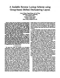
It is desired that a VR respond to VID command immediately and settle its output voltage to a new level with minimum delay to expedite power reduction and processor cooling [13]–[16]. For example, in Intel’s specifications [12], the VR must lower the maximum output voltage to reside within the low-voltage VID window within 50 µs of the final VID code transmission, and respond to a transition from low VID to high VID by regulating the output voltage to the range defined by the new VID code within 50 µs of the final code transmission. However, output capacitors of a VR will try to hold the output voltage from transitioning, since any output voltage change will result in charging or discharging of the output capacitors. Due to the fact that the output inductor current can only ramp up at a fixed slew rate, it takes a certain amount of time for a regulator to supply the load current as well as the charging/discharging current, resulting in DVS transition delay. A large number of bulk capacitors then become a heavy burden for a fast DVS operation. The resulting time delay can cause output voltage to deviate from the reference voltage, or even out of Intel VR design specifications [12]. While reducing output, capacitors can speed up DVS transition. Hence, it is vital to maintain enough output capacitance to meet both static ripple voltage and transient response requirements. Investigation in this paper reveals that the compensation network of the VR also has a big impact on DVS operation. Thus, an alternative way to improve DVS operation could be achieved by modifying the compensation network. In this paper, the operational principles of DVS and impacts of the output capacitors on DVS are addressed first. Then, an active compensator scheme is proposed to improve the DVS performance. Simulation data and experimental results are demonstrated to verify the proposed scheme. II. EFFECTS OF OUTPUT CAPACITANCE AND COMPENSATION ON DVS A simple block diagram of a VR with voltage-mode control in Fig. 1 is employed to demonstrate the operation of DVS. There is a VID interface between the CPU and the pulsewidthmodulation (PWM) controller. A digital–analog converter (DAC) integrated in the controller decodes the logic signals into a discrete analog voltage, which is the reference voltage VREF . Upon receiving VIDs from the CPU, the reference voltage is adjusted and the output voltage VO will be regulated to the desired VID voltage. As mentioned in Section I, output capacitors have a large impact on DVS operation. When the VID is transitioned from high to low, output capacitors need to discharge current to the load. If the processor load is not capable of absorbing output capacitor energy, reverse current may flow
0885-8993/$25.00 © 2008 IEEE Authorized licensed use limited to: University of Central Florida. Downloaded on January 15, 2010 at 14:07 from IEEE Xplore. Restrictions apply.
308
IEEE TRANSACTIONS ON POWER ELECTRONICS, VOL. 24, NO. 1, JANUARY 2009
Fig. 1.
Typical VR with voltage-mode control.
into the regulator’s input filter, potentially charging the input filter to a voltage above the overvoltage value. In another case, when the VID increases from low to high, the voltage regulator will charge output capacitors to increase the output voltage. The VR may experience a large inrush current due to charging of output capacitors. Therefore, the reference voltage of VR usually ramps up or decreases to the targeted VID at a specified slew rate such that the output voltage will alter smoothly. For example, according to the specifications in [12], the microprocessor transitions to its desired operating voltage in a 12.5 mV step every 5 µs. Given the total output capacitance, the relationship between the charging/discharging current and DVS slew rate can be expressed by Icharge = CO
dV dt
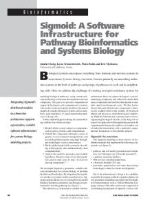
Fig. 2. Experimental data of DVS operation. (Top traces: output inductor current of two phases, bottom traces: output voltage.)
(1)
where Icharge is the charging/discharging current during DVS, CO is the total output capacitance, and dV /dt is the DVS slew rate. It is found that if the DVS slew rate is specified, the total current drawn during DVS is proportional to the output capacitance. Due to time delay caused by the output filters, output voltage may deviate or distort from the reference voltage. Fig. 2 shows experimental waveforms of DVS operation of a multiphase VR. During voltage transitioning, the inductor current is ramping up since extra current is drawn to charge the output capacitors. After the reference voltage reaches its final value, the inductor current returns to the load current slowly. The extra current will be dumped to the output capacitors and cause voltage deviation. Depending on compensation, there is a considerable settling time of the output voltage at the end of the VID transition. The investigation of DVS would not be complete without the inclusion of adaptive voltage positioning (AVP) control [12] since it has become a common industry practice for microprocessor voltage regulation. AVP adjusts the output voltage based on the load current. A typical method to achieve AVP control is to inject the sensed inductor current to the inverted input of the error amplifier (Fig. 1). This current will flow through R1 to
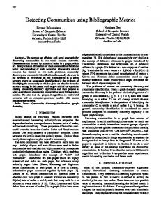
Fig. 3.
Average model of VR in DVS operation.
develop a voltage drop proportional to the load current. During DVS, the inductor current includes both the load current and the charging/discharging current of the output capacitors, as derived in (1). As a result, the sensed inductor current is different from the real load current, and the output voltage may be regulated to a wrong value due to the extra charging/discharging current of the output capacitors. Based on the aforesaid discussions, it is noted that reducing the output capacitance can bring down the total charging or discharging current for DVS. However, certain minimum number of capacitors are usually required to meet both static and dynamic requirements of VR operation. As a result, a method that can optimize DVS operation without change of the VR power stage is desired. In the following discussion, the effect of the compensation network on DVS is studied. Mathematical and simulation analyses show that the compensation network plays an important role in settling the output voltage during DVS operation.
Authorized licensed use limited to: University of Central Florida. Downloaded on January 15, 2010 at 14:07 from IEEE Xplore. Restrictions apply.
IEEE TRANSACTIONS ON POWER ELECTRONICS, VOL. 24, NO. 1, JANUARY 2009
309
The average model of a typical VR with voltage-mode control shown in Fig. 3 is employed to study the effects of compensation on DVS operation. Compared to Fig. 1, a block Gm replaces the PWM modulator and it represents the modulation gain, while the block Vin is the input voltage gain of the power stage. During DVS operation, VREF is varied when receiving the VID codes from the microprocessor. Since the VID transitioning slew rate is limited, i.e., VREF is moved smoothly, a steadystate condition can be approximately assumed during DVS operation. The high gain of the error amplifier then causes the error amplifier output voltage VCOM to adjust rapidly to a new level. VCOM P can be calculated by the reference voltage VREF , input voltage Vin , and the modulation gain Gm VCOM =
D 1 = VREF Gm Gm Vin
(2)
where D is the duty cycle. Since the voltage at inverted input pin of the error amplifier is equal to the reference voltage VREF , the voltage across C1 and R2 in steady state can then be obtained by VCOM − VREF =
Gm Vin − 1 VREF . Gm Vin
(3)
According to (3), while the reference voltage is changing during DVS, the voltage across C1 will also adjust to a new level to regulate the output voltage. The change of VC 1 can be expressed by dVC 1 = dVCOM − dVREF =
Gm Vin − 1 dVREF Gm Vin
(4)
where dVCOM and dVREF are the changes of error amplifier output voltage and reference voltage, respectively. dVC 1 then generates charging/discharging current flowing through R2 and C1 . This current can be given in s-domain by iC (s) = =
1 [VCOM (s) − VREF (s)] R2 + 1/sC1 Gm Vin − 1 1 VREF (s). R2 + 1/sC1 Gm Vin
(5)
For a VR with AVP, (5) is still valid since the sensed inductor current will mainly flow through R1 and adjust the output voltage. From (5), it is found that if the dynamic VID change is specified, the charging/discharging current is related to the capacitor C1 and resistor R2 . This charging/discharging current will eventually flow through compensation components R1 , R3 , and C3 and develop a voltage deviation between output voltage VO and reference voltage VREF during the DVS voltage transition, resulting in settling time. Thus, both the voltage deviation and settling time depend largely on the R2 C1 time constant. If the R2 C1 time constant is too large, it will cause a long settling time and large voltage deviation during DVS operation. III. PROPOSED ACTIVE COMPENSATOR SCHEME FOR DVS The aforesaid analysis suggests that both voltage deviation and settling time of DVS depend on the operating voltage across C1 . With a short R2 C1 time constant, the voltage deviation and settling time in DVS operation can be reduced. However,
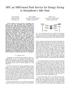
Fig. 4. Proposed active compensator scheme for DVS operation. (a) Block diagram. (b) Simulation results.
R2 C1 is typically determined by the whole control loop. Once the power stage and compensation have been optimized, any change of the RC network may result in overall loop gain and phase margin drift that may lead to system instability. Therefore, a method that can improve DVS without impact on the loop stability is desired. Careful analysis reveals that if a specific current can be generated to compensate the charging/discharging current provided for the voltage change of the capacitor C1 , as given in (5), the output voltage deviation will be minimized during DVS operation. Based on this observation, an active compensator scheme is proposed. This scheme consists of a voltage doubler in series with an RC network RD and CD . The voltage doubler is connected to the VREF pin (positive input of the error amplifier), while the RC network is connected to the inverting input of the error amplifier, as shown in Fig. 4(a). Since the inverting pin voltage is equal to the reference voltage, a voltage equal to the reference voltage is generated across the RC network due to the voltage doubler. In normal operation, where the reference voltage is stable, the voltage across the RC network is dc and no current will be generated. During DVS operation, a changing voltage equal to the reference voltage is developed across RD and CD . As a result, a current is generated and will offset the charging/discharging current flowing through the compensation
Authorized licensed use limited to: University of Central Florida. Downloaded on January 15, 2010 at 14:07 from IEEE Xplore. Restrictions apply.
310
IEEE TRANSACTIONS ON POWER ELECTRONICS, VOL. 24, NO. 1, JANUARY 2009
capacitor C1 . The current flowing through the active compensator network can be written as iDVS (s) =
1 VREF (s). RD + (1/sCD )
(6)
In order for iDVS to counter the charging/discharging current iC from C1 , (5) must be equal to (6). Manipulating these two equations leads to the design formula for RD and CD R D = KD R 2 CD =
C1 KD
(7) (8)
where KD =
Gm Vin . Gm Vin − 1
(9)
It suggests that if RD and CD are designed such that (7)–(9) are met, then the active compensator will provide a current iDVS that is equal to the required current to charge or discharge the capacitor C1 during DVS. As a result, there will be less voltage deviation and shorter settling time of the output voltage during DVS. Since the proposed active compensator comes into play only during DVS, and the VID transitioning slew rate is fairly slow, as mentioned in Section II, steady-state operation can be assumed during DVS operation. Therefore, the proposed active compensator scheme has no impact on system small-signal performance, e.g., closed-loop gain and output impedance. PSPICE simulation results in Fig. 4(b) are provided to verify this proposed scheme. Without the active compensator, there is a significant deviation between VO and VREF , while this deviation is reduced to a large extent by applying the proposed active compensator. IV. EXPERIMENTAL RESULTS A voltage regulator prototype was developed to verify the proposed active compensator scheme. The circuit parameters are as follows: = 12 V; Vin = 1.1–1.4 V; VO Switching frequency = 500 kHz. Controller ISL6333 from Intersil; Output inductors THCBR1290-221-R from Delta (L = 220 nH); Output capacitance 5 × 560 µF polymer capacitors + 18 × 22 µF MLCC. The voltage doubler of the active compensator is integrated in the controller ISL6333 [17], where a pin “DVC” is designated for the active compensator design. The compensation components R2 , C1 , and designed active compensator values are given as R2 = 12.1 kΩ; C1 = 1000 pF; RD = 14 kΩ; CD = 820 pF. where the components are chosen based on standard industry values. Fig. 5(a) shows experimental results of DVS operation
Fig. 5. Comparison of DVS operation for VR with and without active compensator. (Top trace: V R E F , bottom trace: V O ). (a) Without active compensator. (b) With proposed active compensator.
without the proposed scheme. When the VID voltage VREF changes from 1.1 to 1.4 V within 120 µS, the output voltage VO exhibits about 29-mV voltage overshoot and undershoot during each DVS transition. Also, VO settles down to its final value fairly slow due to the large R2 C1 time constant. With the proposed active compensator, the experimental results are shown in Fig. 5(b). It is found that the proposed active compensator scheme significantly improves the DVS performance with much less voltage deviation and settling time, even though the same compensation and power stage parameters are implemented.
Authorized licensed use limited to: University of Central Florida. Downloaded on January 15, 2010 at 14:07 from IEEE Xplore. Restrictions apply.
IEEE TRANSACTIONS ON POWER ELECTRONICS, VOL. 24, NO. 1, JANUARY 2009
V. CONCLUSION Although the DVS technique is a common industry practice to improve the efficiency of microprocessor operation, VR designers are facing challenges such as output voltage deviation and slow settling time. While reducing output capacitance and changing compensation may help improve DVS, the improvement comes at the cost of sacrificing static and dynamic performances. In this paper, an active compensator was proposed to improve the DVS operation without changing the power stage and compensation. Simulation data and experimental results have verified the effectiveness of this new scheme. ACKNOWLEDGMENT The authors would like to acknowledge R. Isham at Intersil for proposing this scheme and developing ICs with it. REFERENCES [1] V. Von Kaenel, P. Macken, and M. G. R. Degrauwe, “A voltage reduction technique for battery-operated systems,” IEEE J. Solid-State Circuits, vol. 25, no. 5, pp. 1136–1140, Oct. 1990. [2] P. Macken, M. Degrauwe, M. Van Paemel, and H. Oguey, “A voltage reduction technique for digital systems,” in IEEE 37th Int. Solid-State Circuits Conf., Tech. Dig., San Francisco, CA, Feb. 14–16, 1990, pp. 238– 239. [3] L. S. Nielsen, C. Niessen, J. Sparso, and K. van Berkel, “Low-power operation using self-timed circuits and adaptive scaling of the supply voltage,” IEEE Trans. Very Large Scale Integr. (VLSI) Syst., vol. 2, no. 4, pp. 391–397, Dec. 1994. [4] F. Yao, A. Demers, and S. Shenker, “A scheduling model for reduced CPU energy,” in Proc. 36th Annu. Symp. Found. Comput. Sci., Milwaukee, WI, Oct. 23–25, 1995, pp. 374–382. [5] B. Davari, R. H. Dennard, and G. G. Shahidi, “CMOS scaling for high performance and low power—the next ten years,” Proc. IEEE, vol. 83, no. 4, pp. 595–606, Apr. 1995.
311
[6] T. Kuroda, K. Suzuki, S. Mita, T. Fujita, F. Yamane, F. Sano, A. Chiba, Y. Watanabe, K. Matsuda, T. Maeda, T. Sakurai, and T. Furuyama, “Variable supply-voltage scheme for low-power high-speed CMOS digital design,” IEEE J. Solid-State Circuits, vol. 33, no. 3, pp. 454–462, Mar. 1998. [7] T. D. Burd, T. A. Pering, A. J. Stratakos, and R. W. Brodersen, “A dynamic voltage scaled microprocessor system,” IEEE J. Solid-State Circuits, vol. 35, no. 11, pp. 1571–1580, Nov. 2000. [8] J. R. Lorch and A. J. Smith, “PACE: A new approach to dynamic voltage scaling,” IEEE Trans. Comput., vol. 53, no. 7, pp. 856–869, Jul. 2004. [9] L. Yuan and G. Qu, “Analysis of energy reduction on dynamic voltage scaling-enabled systems,” IEEE Trans. Comput.-Aided Design Integr. Circuits Syst., vol. 24, no. 12, pp. 1827–1837, Dec. 2005. [10] B. H. Calhoun and A. P. Chandrakasan, “Ultra-dynamic voltage scaling (UDVS) using subthreshold operation and local voltage dithering,” IEEE J. Solid-State Circuits, vol. 41, no. 1, pp. 238–245, Jan. 2006. [11] J. Mao, C. G. Cassandras, and C. Zhao, “Optimal dynamic voltage scaling in energy-limited nonpreemptive systems with real-time constraints,” IEEE Trans. Mobile Comput., vol. 6, no. 6, pp. 678–688, Jun. 2007. [12] Voltage Regulator-Down (VRD) 11.0 Processor Power Delivery Design Guidelines for Desktop LGA775 Socket Intel Corporation. (2006). [Online]. Portland, OR. Available: http:/www.intel.com [13] G.-Y. Wei and M. Horowitz, “A fully digital, energy-efficient, adaptive power-supply regulator,” IEEE J. Solid-State Circuits, vol. 34, no. 4, pp. 520–528, Apr. 1999. [14] O. Trescases and W. T. Ng, “Variable output, soft-switching dc/dc converter for VLSI dynamic voltage scaling power supply applications,” in Proc. IEEE Power Electron. Spec. Conf., Jun. 20–25, 2004, vol. 6, pp. 4149–4155. [15] A. Soto, P. Alou, and J. A. Cobos, “Design methodology for dynamic voltage scaling in the buck converter,” in Proc. IEEE Appl. Power Electron. Conf., Austin, TX, Mar. 6–10, 2005, vol. 1, pp. 263–269. [16] J. Song, G. Yoon, and C. Kim, “An efficient adaptive digital dc–dc converter with dual loop controls for fast dynamic voltage scaling,” in Proc. IEEE Custom Integr. Circuits Conf. 2006, San Jose, CA, Sep. 10–13, pp. 253–256. [17] ISL6333: Three-Phase Buck PWM Controller with Integrated mosfet Drivers and Light Load Efficiency Enhancements for Intel VR11.1 Applications. Datasheet. Intersil Corporation. (2008). [Online]. Milpitas, CA. Available: http://www.intersil.com
Authorized licensed use limited to: University of Central Florida. Downloaded on January 15, 2010 at 14:07 from IEEE Xplore. Restrictions apply.