ARTICLE International Journal of Advanced Robotic Systems
An Adaptive Fuzzy Control Approach for the Robust Tracking of a MEMS Gyroscope Sensor Regular Paper
Juntao Fei, Wanru Juan and Tianhua Li Jiangsu Key Laboratory of Power Transmission and Distribution Equipment Technology College of Computer and Information, Hohai University, P. R. China *Corresponding author e-mail:
[email protected] Received 20 Oct 2011; Accepted 19 Dec 2011 © 2011 Fei et al.; licensee InTech. This is an open access article distributed under the terms of the Creative Commons Attribution License (http://creativecommons.org/licenses/by/3.0), which permits unrestricted use, distribution, and reproduction in any medium, provided the original work is properly cited.
Abstract In this paper, a direct adaptive fuzzy control using a supervisory compensator is designed for the robust tracking of a MEMS gyroscope sensor. The parameters of the membership functions are adjusted according to the designed adaptive law for the purpose of tracking a reference trajectory. A fuzzy controller that can approximate the unknown nonlinear function and compensate the system’s nonlinearities is incorporated into the adaptive control scheme in the Lyapunov framework. A supervisory compensator is adopted to guarantee the stability of the closed loop system. Numerical simulations for a MEMS angular velocity sensor are investigated in order to verify the effectiveness of the proposed adaptive fuzzy control scheme and show that the system using the designed fuzzy controller with a supervisory compensator has better tracking performance and robustness than that using only a fuzzy control without a supervisory compensator in the presence of external disturbances. Keywords adaptive fuzzy control; supervisory compensator; approximation error.
1. Introduction Gyroscopes are commonly used sensors for measuring angular velocity in many areas of application, such as navigation, homing and control stabilisation. The performance of the MEMS gyroscope often deteriorates due to the effects of time‐varying parameters as well as noise sources, such as mechanical and circuitry noise, quadrature errors, parameter variations and external disturbances. It is necessary to use an advanced control, such as adaptive control or intelligent control, to control MEMS gyroscopes and in the last few years, various control approaches have been developed. Increasing attention has been given to the tracking control of MEMS gyroscopes. Leland [1] derived two adaptive controllers for a vibrational MEMS gyroscope which tune the drive axis’ natural frequency and the sense axis’ vibration to zero by a force‐to‐rebalance operation. Batur et al. [2] developed a sliding mode control for a MEMS gyroscope. Sun et al. [3] derived a phase‐domain design approach in order to study the mode‐matched control of gyroscopes. Antonello et al. [4] used an extremum‐seeking control to
www.intechweb.org
J Adv Robotic Sy, 2011,Fuzzy Vol. Control 8, No. 5,Approach 125-133 Juntao Fei, Wanru Juan andIntTianhua Li: An Adaptive for the Robust Tracking of a MEMS Gyroscope Sensor
125
automatically match the vibration mode in MEMS vibrating gyroscopes. Park et al. [5] presented an adaptive controller for a MEMS gyroscope which drives both of the axes of vibration and controls the entire operation of the gyroscope. Some adaptive sliding mode controllers have been developed to control MEMS gyroscopes [6‐7]. System nonlinearities are inevitable in actual engineering and they require the controller to be either adaptive or robust. Intelligent control approaches such as neural networks and fuzzy control do not require mathematical models and have the ability to approximate nonlinear systems. Neural network technologies have been applied to nonlinear control systems [8‐9]. Wang [10] proposed a universal approximation theorem and demonstrated that an arbitrary function of a certain set of functions can be approximated with arbitrary accuracy using a fuzzy system over a compact domain. Therefore a fuzzy logic system for approximating arbitrary nonlinear functions makes it a useful tool for adaptive applications. The key idea behind adaptive fuzzy logic systems is that a wide class of nonlinear systems can be approximated to arbitrary closeness by them. An adaptive fuzzy sliding mode controller combines the merits of a sliding mode control, a fuzzy inference mechanism and an adaptive algorithm. Guo et al. [11] proposed an adaptive fuzzy sliding mode controller for a robot manipulator. Tong et al. [12] designed a fuzzy indirect and direct adaptive control for a nonlinear system. Yoo et al. [13] developed adaptive controller for a robot manipulator using a fuzzy compensator. Wai et al. [14] presented an adaptive fuzzy neural network control design via a T–S fuzzy model for a robot manipulator which included actuator dynamics. Wai et al. [15] investigated an adaptive sliding mode control system for an indirect field‐oriented induction motor drive so as to track periodic commands. Lee [16] proposed a robust adaptive fuzzy control by back‐stepping for a class of MIMO nonlinear systems. Islam et al. [17] used a robust adaptive fuzzy output feedback control system for robot manipulators. Zhou et al. [18] developed an adaptive output‐feedback fuzzy tracking control for a class of nonlinear systems. However, the application of fuzzy control to MEMS gyroscopes has never been performed in the literature and, therefore, it is necessary to adopt an adaptive fuzzy control that can adjust the parameter vector of the member functions on‐line using an adaptive law for the vibration control of MEMS gyroscopes. This paper focuses on the design of a direct adaptive fuzzy control for a MEMS gyroscope using a supervisory compensator. A direct adaptive fuzzy controller use fuzzy logic systems as controllers; therefore linguistic fuzzy control rules can be directly incorporated into the controller. The contribution of this paper lies is the integration of an adaptive control, a nonlinear approximation of a fuzzy control and a supervisory compensator. The study of the
126 Int J Adv Robotic Sy, 2011, Vol. 8, No. 5, 125-133
adaptive fuzzy controller is conducted on a MEMS gyroscope and it is applied to control the gyroscope and guarantee that the closed loop system is globally stable and tracking errors are as small as possible. In order to guarantee the robustness of the adaptive fuzzy controller, a supervisory compensator is incorporated into the adaptive fuzzy control scheme in the Lyapunov framework. This paper is organised as follows. In section 2, the dynamics of the MEMS gyroscope are introduced and a non‐ dimensional procedure is described. In section 3, an adaptive fuzzy control is derived and Lyapunov analysis is implemented to guarantee the asymptotic stability of the closed‐loop system. Simulation results are presented in section 4 to verify the effectiveness of the proposed adaptive fuzzy control. Conclusions are provided in section 5. 2. Dynamics of the Mems gyroscope The dynamics of the MEMS gyroscope are described in Fig. 1. A typical MEMS gyroscope configuration includes a proof mass suspended by spring beams, electrostatic actuations and sensing mechanisms for forcing an oscillatory motion and sensing the position and velocity of the proof mass, as well as a rigid frame which is rotated along the rotation axis. The dynamics of a MEMS gyroscope are derived by Newton’s Law in the rotating frame.
y k xx
z
k yy
d yy
k xx
m
Proof Mass
d xx
d xx k yy
x
d yy
Figure 1. Simplified model of a z‐axis MEMS gyroscope.
In a z‐axis gyroscope, by supposing the stiffness of spring in direction z to be much larger than that in directions x, y, the motion of the poof mass is constrained to just along the x‐y plane. Assume that the measured angular velocity is almost constant over a long enough time interval. Considering fabrication imperfections which cause extra coupling between the x and y axes, and ignoring centrifugal forces, the governing equation for a z‐axis MEMS gyroscope is simplified as:
mx d xx x d xy y k xx x k xy y u x 2m z y my d xy x d yy y k xy x k yy y u y 2m z x
(1)
www.intechweb.org
where x and y are the coordinates of the proof mass with respect to the gyro frame in a Cartesian coordinate system. In equation (1) d xx and d yy are damping coefficients; k xx and k yy are spring coefficients; d xy and
k xy , quadrature errors, all of which are coupled damping and spring terms, respectively, mainly due to the asymmetries in suspension structure and the misalignment of sensors and actuators. The coupled spring and damping terms are unknown, but can be assumed to be small. The nominal values of the x and y axes’ spring and damping terms are known, but there are small unknown variations. The proof mass can be determined accurately.
3. Adaptive Fuzzy Controller Design Fuzzy control is very robust and capable of handling nonlinear systems, providing a methodology for representing, manipulating and implementing a human’s heuristic knowledge about how to control a system. A fuzzy controller is composed of the following four elements: fuzzier, some fuzzy IF‐THEN rules, a fuzzy inference engine and a defuzzifier. The fuzzy inference engine uses the fuzzy IF‐THEN rules to perform a mapping from an input linguistic vector
x x1 , x2 , , xn R n to an output variable T
y R . The i‐th fuzzy rule can be expressed as:
R i : If xi is A1i and … x n is Ani ,then y is y i (5)
2
Dividing both sides of equation (1) by m , q0 , w0 , which are a reference proof mass of a gyroscope, the length and natural resonance frequency respectively, yields the non‐ dimensional motion equation as: 2
x d xx x d xy y wx x wxy y ux 2 z y y d xy x d yy y wxy x wy 2 y u y 2 z x (2) where
mw0
2
where
A
,…,
i n
A
y
are fuzzy variables and
i
is a
singleton number. The output of the fuzzy system can be expressed using a centre‐average defuzzifier, product inference and a singleton fuzzifier:
n i i x j y A j i 1 j 1 T ( x ) y( x ) uc x (6) r n Ai x j j i 1 j 1 where Ai x j is the membership function value of the r
d d d xx d xx , xy d xy , yy d yxy z z , mw0 w0 mw0 mw0
k xx
i 1
wx
k yy mw0
2
k xy
wy
mw0
2
wxy
, , . The vector form of the MEMS gyroscope dynamic model can be written as: q Dq K b q u 2q (3)
0 z ux x where q , u , , z 0 y uy d xx D d xy
wx d xy , K b d yy w xy
2
w xy 2 w y
j
x j , r is the number of fuzzy rules and
fuzzy variable
y , y , , y r is an adaptive parameter vector. T
1
2
x 1 ( x ), 2 ( x ), , M ( x )T
is fuzzy
basis function vector and n
x
x j 1
i
Aij
j
n Ai x j j j 1 i 1 n
is i‐th column vector of
.
fuzzy basis function vector. If D , K b and are unknown, (3) can be rewritten as: Control objective: i. The control target for the MEMS gyroscope is to f ( q,q ) u (4) q maintain the proof mass so as to oscillate in the x and y directions at a given frequency and amplitude: where f ( q,q ) is an unknown dynamic function xm A1 sin(1t), ym A2 sin(2t ). f ( q,q ) ( D 2 )q K b q . Fuzzy control will be ii. The closed loop system must be globally stable in the investigated in order to approximate the unknown sense that all variables x( t ), ( t ) and uc x must be function in the next section.
www.intechweb.org
uniformly stable. The tracking error should be as small as possible.
Juntao Fei, Wanru Juan and Tianhua Li: An Adaptive Fuzzy Control Approach for the Robust Tracking of a MEMS Gyroscope Sensor
127
The procedure of the proposed adaptive fuzzy control as applied to the MEMS gyroscope is described in this section. The proposed adaptive fuzzy control scheme is shown by Fig. 2.
0 , kd 0 . 1
where bc
Choosing the control force:
Rewriting (3) as:
u *
q ( D 2) q K b q u (7)
The reference model is defined as:
qm K m qm
where K m
( D 2) q kb q qm k T e (13)
the controller
u
*
will force the tracking error
e( t ) to T
converge to zero, where e (e, e) and k ( k 2 , k1 ) 0 (8) 2 are chosen such that all roots of s k1 s k 2 0 are T
located on the left side of the s plane. The dynamic of tracking error can be derived as:
diag{12 , 2 2 , 3 2 } .
Rewriting (8) as:
qm K m qm (9)
Re ference Model qm u u c ( x | ) u d ( x)
System Output q
q ( D 2)q K b q u
e qm ( D 2) q kb q u
(14)
qm ( D 2) q kb q uc ( x | ) ud ( x)
Substituting (13) into (14) yields:
e k T e u * uc ( x | ) ud ( x) (15)
Tracking Error e
or equivalently:
e
uc ( x | ) T ( x )
e bc [u * uc ( x | ) ud ( x)] (16)
0 1 where . Since is a stable matrix, there k2 k1
(0) 22 ) ( x) (ep12 ep
exists a unique positive definite and symmetrical matrix P , satisfying the Lyapunov equation:
ud ( x) kd sgn(eT Pbc )
Fig. 2. Block diagram of the adaptive fuzzy control system. The tracking error is defined as:
controller
ud ( x) :
uc ( x | )
where P
e qm q (10)
Suppose that the controller
T P P Q (17)
u is composed of a fuzzy
matrix. We define the optimal parameter vector thus:
and a supervisory compensator
u uc ( x | ) ud ( x) (11)
n
n mi xR
Ri 1
(18)
uc ( x | * ) u * (19)
N
As such, (16) becomes:
,
i
* arg min [sup | uc ( x | ) u * |]
The fuzzy approximation error vector is defined as:
where the fuzzy controller
uc ( x | ) ii ( x) T ( x) ( x) is a fuzzy
p p 11 12 , Q is an arbitrary positive definite p21 p22
basis function, the supervisory compensator ud ( x) is:
e e bc [u x ( x | * ) uc ( x | )] bc ud ( x) bc
T
ud ( x ) k d sgn(e Pbc ) (12)
e bc ( * )T ( x) bc ud ( x) bc
(20)
128 Int J Adv Robotic Sy, 2011, Vol. 8, No. 5, 125-133
www.intechweb.org
e 0 .
We define the Lyapunov function candidate:
1 1 * ( )T ( * ) (21) V eT Pe 2 2
where is a positive constant.
Suppose M
bc ( * )T ( x ) bc ud ( x) bc ,
then (20) becomes e
e M
.
Differentiating V with respect to time yields:
1 1 T 1 V e Pe eT P e ( * )T 2 2 1 1 1 (e M )T Pe eT P e M ( * )T 2 2 1 1 1 1 eT (T P P)e M T Pe eT PM ( * )T 2 2 2 1 T 1 * T T e Qe e PM ( ) 2 1 T 1 T e Qe e Pbc [( * )T ( x) ud ( x) ] ( * )T 2 1 T 1 * e Qe ( )T [ eT Pbc ( x) ] eT Pbcud ( x) eT Pbc 2
R e R n V ( e ) 0 then if R contains no trajectories other than e 0 , the origin zero is asymptotically stable. Therefore, e 0 is an invariant set defining
which implies that any trajectory starting from an initial condition within that set remains in the set constantly, that is e( t ) will asymptotically converge on zero.
4. Simulation Study In this section, we will evaluate the proposed adaptive fuzzy control approach on the lumped MEMS gyroscope sensor model [1] [5] by using MATLAB/SIMULINK. The control objective is to maintain the system to track the desired reference trajectory and adopt the adaptive fuzzy controller for the gyroscope model. The parameters of the (22) MEMS gyroscope sensor are shown as follows:
x2 355.3, y2 532.9, xy 70.99.d xx 0.01, d yy 0.01, d xy 0.002, 0.1
The desired motion trajectories are
If we choose the adaptive law:
eT Pbc ( x) (ep12 e p22 ) ( x) (23)
ym 1.2sin(2t ),
2 5.11kHz .
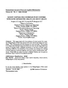
P2 (x) exp((x 1.5)2 ) , P3 ( x) 1/ (1 exp(5( x 2))) 1
0.9
Membership function degree
0.8
1 T 2 V e Qe min (Q ) e 0 (25) 2
Here, we use the inequality:
0.7 0.6 0.5 0.4 0.3 0.2
2
min ( Q ) e eT Qe max ( Q ) e
2
0.1
(26)
0 -3
-2
-1
0 x,y
where min ( Q ) is the eigenvalue of the matrix Q with a minimum real part.
V 0 , V becomes negative semi‐definite and ensures that V , e and are all bounded. LaSalle’s invariant set theorem can be used to prove that lim e( t ) 0 . V 0 implies that e
t
0 and that there is no other solution but
www.intechweb.org
membership
N1 ( x) exp(( x 0.5)2 ) , P1 ( x) exp(( x 0.5) 2 )
six
N3 (x) 1/ (1 exp(5(x 2))) , N 2 ( x ) exp( ( x 1.5) 2 )
supt 0 | | , (24) becomes:
following
then substituting (23) into (22) yields:
1 V eT Qe eT Pbc ud ( x) eT Pbc 2 (24) 1 T T e Qe | e Pbc | (supt 0 | | kd ) 2
xm sin(1t ),
1 6.71kHz ,
where
The
functions are selected in the region [‐3,3] respectively, as shown by Fig. 3.
Choosing k d
According to LaSalle’s invariant set theorem,
1
2
3
Figure 3. Curve of membership functions.
In the simulation, we allowed 10% parameter variations for the spring and damping coefficients with respect to their nominal values. We further assumed a 10% magnitude change in the coupling terms. The
t
T
external disturbance f1 10 sin( ),10 cos(t ) and 4 5 Juntao Fei, Wanru Juan and Tianhua Li: An Adaptive Fuzzy Control Approach for the Robust Tracking of a MEMS Gyroscope Sensor
129
f 2 [10sin(500 t ),10 cos(1000t )]T . The initial 5 states of the system are [1,0,0,0], the initial values of i
1.5
1
i ( 0 ) 0 , where i is i‐th column vector of the estimated parameter matrix , adaptive gain is chosen as 600 in (23), k (k2 , k1 )T is chosen as
x Position tracking
are
0.5
0
-0.5
k1 2, k2 1 in (16) to satisfy that all of the roots of
-1
s k1s k 2 0 are located on the left side of the s
-1.5
2
plane, Q is an arbitrary positive definite matrix, chosen as
Q =[50 0;0 50] in (17) and kd should be a positive
constant since k d
y Position tracking
e Pbc .
u uc ( x | )
and
u uc ( x | ) u d ( x )
t f1 10sin( ),10 cos(t ) 4 5
25
30
0
5
10
15 time(s)
20
25
30
0.5
0
-0.5
-1.5
Figure 4. Property of the tracking trajectory
u uc ( x | ) 0.8 0.6
uc ( x | ) . It can be
observed the tracking error is relatively large which is around the value of 0.2. Figs. 6 and 7 depict the position‐ tracking trajectory and tracking errors of x, y using
-0.4
0
5
10
15 time(s)
20
25
30
0
5
10
15 time(s)
20
25
30
1 0.8
u uc ( x | ) ud ( x) . It can be seen that the system using a supervisory compensator ud ( x) has better
y Position tracking error
0.6
trajectory‐tracking performance than that which uses only a fuzzy controller uc ( x | ) , and the position of x, y can track
130 Int J Adv Robotic Sy, 2011, Vol. 8, No. 5, 125-133
0 -0.2
-1
and
the position of the reference model in a short time with the supervisory compensator. Therefore, it can be seen that the adaptive fuzzy tracking performance is satisfactory, the MEMS gyroscope can maintain the proof mass to oscillate in the x, y direction at a given frequency and amplitude with the proposed adaptive fuzzy control.
0.2
-0.8
tracking error is almost zero. Figs. 4‐7 compare the tracking
uc ( x | )
0.4
-0.6
It can be seen here that the
error between the system using
using
1
will be simulated as x Position tracking error
tracking errors of x, y only using u
T
shown by Figs. 4‐9. Figs. 4 and 5 show that the position‐tracking trajectory and
20
-1
respectively. The tracking responses for these two different fuzzy controllers in the presence of the disturbance
u uc ( x | ) ud ( x) .
15 time(s)
,
T
First, we simulate the system response of MEMS gyroscope with
10
1
In order to eliminate chattering, the discontinuous control component in (11) can be replaced by a smooth‐sliding mode component to yield: where s
5
1.5
150 in (12).
u uc ( x | ) ud ( x ) T ( x) kd tanh(eT Pbc )
0
0.4 0.2 0 -0.2 -0.4 -0.6 -0.8 -1
Figure 5. Property of the tracking error using uc ( x | )
www.intechweb.org
1.5
800 600
400
0.5
x Control input
x Position tracking
1
0
200
0
-0.5
-200 -1
-1.5
-400
0
5
10
15 time(s)
20
25
30
-600
1.5
0
5
10
15 time(s)
20
15 time(s)
20
25
30
1000
1
y Control input
y Position tracking
500 0.5
0
-0.5
0
-500
-1
-1000 -1.5
0
5
10
15 time(s)
20
25
30
-1500
Figure 6. Property of the tracking trajectory using
u uc ( x | ) u d ( x )
0
5
10
Figure 8. Control inputs using u
25
30
uc ( x | ) u d ( x )
1
200
0.8
150
0.4
100
0.2
50
0
S1
x Position tracking error
0.6
-0.2 -0.4
0 -50
-0.6
-100
-0.8 -1
0
5
10
15 time(s)
20
25
30
-150
-200
0
5
10
1 0.8
20
25
30
200
0.6
150
0.4 100
0.2
50
0 -0.2
S2
y Position tracking error
15 time(s)
-0.4
0 -50
-0.6 -100
-0.8 -1
Figure
-150
0
5
7.
10
Property
15 time(s)
of
u uc ( x | ) u d ( x )
the
20
tracking
25
30
error
-200
0
5
10
using
15 time(s)
20
Figure 9. Property of the sliding surface
25
30
s e Pbc using
u uc ( x | ) u d ( x )
www.intechweb.org
Juntao Fei, Wanru Juan and Tianhua Li: An Adaptive Fuzzy Control Approach for the Robust Tracking of a MEMS Gyroscope Sensor
T
131
Fig. 8 plots the adaptive fuzzy control inputs using
1
u uc ( x | ) ud ( x) . It can be seen that the chattering
s eT Pbc using u uc ( x | ) ud ( x) , showing that
0.6 x Position tracking error
is diminished because of the use of a smooth supervisory sliding controller which can create a small boundary layer around the switching surface in which the trajectory will remain. Fig. 9 illustrates the property of the sliding surface
0.8
it converges to zero asymptotically. In order to show the robustness of the performance of the MEMS gyroscope, the disturbance
f2 [100sin(500 t ),100cos(1000t )] 5
T
u uc ( x | ) ud also has better performance than one using only u uc ( x | ) ; the
tracking error can still approach zero in a short time, showing that the robustness of the system using (11) is better than that using the fuzzy controller u
uc ( x | )
in the presence of external disturbances.
5
10
15 time(s)
20
15 time(s)
20
25
30
1
0.6 0.4 0.2 0 -0.2 -0.4 -0.6 -0.8 -1
0
5
10
25
30
disturbances
0.6 x Position tracking error
0
u uc ( x | ) ud with large magnitude and high frequency
1
0.4 0.2 0 -0.2 -0.4 -0.6 -0.8 0
5
10
15 time(s)
20
25
30
0
5
10
15 time(s)
20
25
30
1 0.8 0.6 y Position tracking error
-1
Figure 11. Property of tracking error using fuzzy controller
0.8
0.4 0.2 0 -0.2 -0.4 -0.6 -0.8
Figure 10. Property of tracking error using fuzzy controller
u uc ( x | ) with a large magnitude and high frequency
disturbances
132 Int J Adv Robotic Sy, 2011, Vol. 8, No. 5, 125-133
-0.4
0.8
the system using
-1
0 -0.2
-0.8
with a large
magnitude and a high frequency is considered in the simulation. Comparing Figs. 10 and 11, we can see that in the case of a high‐frequency sinusoidal disturbance signal
-1
0.2
-0.6
y Position tracking error
0.4
5. Conclusion A fuzzy logic‐based adaptive control for an angular velocity sensor is presented in this paper. An adaptive fuzzy controller that can incorporate fuzzy control rules directly into itself is used to adaptively adjust the parameters of member functions and make the tracking error as small as possible. Moreover, a supervisory compensator is added to the adaptive fuzzy control system in order to guarantee the asymptotically stability of the control system. A simulation study is implemented to verify the effectiveness of the proposed adaptive fuzzy control in relation to external disturbances. It can be concluded that the dynamic gyroscope system’s responses are as expected, and adaptive fuzzy control with a supervisory compensator has better tracking performance and tracking errors asymptotically converge on zero. 6. Acknowledgments The authors would like to thank the anonymous reviewer for useful comments that improved the quality of the manuscript. This work is partially supported by the National Science Foundation of China under Grant No. 61074056, The Natural Science Foundation of Jiangsu
www.intechweb.org
Province and under Grant No. BK2010201, Scientific Research Foundation for the Returned Overseas Chinese Scholars, State Education Ministry. 7. References [1] R. Leland, Adaptive control of a MEMS gyroscope using Lyapunov methods, IEEE Trans. on Control Systems Technology, 14(2),pp. 278–283, 2006. [2] C. Batur, T. Sreeramreddy, Sliding mode control of a simulated MEMS gyroscope, ISA Transaction, 45(1), pp. 99‐108, 2006 . [3] W. Sung, Y. Lee, On the mode‐matched control of MEMS vibratory gyroscope via phase‐domain analysis and design, IEEE/ASME Trans. on Mechatronics, 14(4), pp. 446‐455, 2009. [4] R. Antonello, L. Oboe, F. Prandi, F. Biganzoli, Automatic mode matching in MEMS vibrating gyroscopes using extremum‐seeking control, IEEE Trans. on Industrial Electronics, 56(10), pp. 3880‐ 3891, 2009. [5] R. Park, R. Horowitz, S. Hong, Y. Nam, Trajectory‐ switching algorithm for a MEMS gyroscope, IEEE Trans. on Instrumentation and Measurement, 56(60), pp. 2561‐2569, 2007. [6] J. Fei, C. Batur, A novel adaptive sliding mode control with application to MEMS gyroscope, ISA Transaction, 48(1), pp. 73‐78, 2009. [7] J. Fei, Robust adaptive vibration tracking control for a MEMS vibratory gyroscope with bound estimation, IET Control Theory and Application, 4(6), pp. 1019‐ 1026, 2010. [8] B. S. Park, S. J. Yoo, J. B. Park, Y. H. Choi, Adaptive neural sliding mode control of nonholonomic wheeled mobile robots with model uncertainty, IEEE Trans. on Control System Technology, 17(1), pp. 207‐ 214, 2009.
[9] M. Lee, Y. Choi, An adaptive neucontroller using RBFN for robot manipulators, IEEE Trans. on Industrial Electronics, 51(3), pp. 711‐717, 2004. [10] L. Wang, Adaptive Fuzzy Systems and Control‐ design and Stability Analysis. New Jersey: Prentice Ha1l, 1994. [11] Y. Guo, P. Woo, An adaptive fuzzy sliding mode controller for robotic manipulators, IEEE Trans. on Systems, Man and Cybernetics‐Part A: Systems and Humans, 33(2), pp. 149‐159, 2004. [12] S. Tong, J. Zhou, Design and stability of fuzzy indirect and direct adaptive control for nonlinear system, Journal of Control and Decision, 15(3), pp. 294‐296, 2000. [13] B. Yoo, W. Ham, Adaptive control of robot manipulator using fuzzy compensator, IEEE Trans. on Fuzzy Systems, 8(2), pp. 186‐199, 2000. [14] R. J. Wai, Z. Yang, Adaptive fuzzy neural network control design via a T–S fuzzy model for a robot manipulator including actuator dynamics, IEEE Trans. on Systems, Man, and Cybernetics, Part B: Cybernetics, 38(5), pp. 1326‐1346, 2008. [15] R. J. Wai, Fuzzy sliding‐mode control using adaptive tuning technique, IEEE Trans. on Industrial Electronics, 54(1), pp. 586‐594, 2007. [16] H. Lee, Robust adaptive fuzzy control by backstepping for a class of MIMO nonlinear systems, IEEE Trans. on Fuzzy Systems, 19(2), pp.265‐275, 2011. [17] S. Islam, P. X. Liu, Robust adaptive fuzzy output feedback control system for robot manipulators, IEEE/ASME Trans. on Mechatronics, 16(2), pp. 288‐ 296, 2011. [18] Q. Zhou, P. Shi, J. Lu, S. Xu, Adaptive output‐ feedback fuzzy tracking control for a class of nonlinear systems, IEEE Trans. on Fuzzy Systems, 19(5), pp. 972‐982, 2011.
www.intechweb.org
Juntao Fei, Wanru Juan and Tianhua Li: An Adaptive Fuzzy Control Approach for the Robust Tracking of a MEMS Gyroscope Sensor
133