Proceedings of the 2006 IEEE International Conference on Robotics and Automation Orlando, Florida - May 2006
An Agent-based Mobile Robot System Using Configurable SOC Technique Yan Meng Stevens Institute of Technology Hoboken, New Jersey, USA Email:
[email protected] Abstract – To make a mobile robot with real-time vision system adapt to the highly dynamic environments and emergencies under the real-time constraints, a significant account of processing power is needed. Instead of pushing the limit of software development and computational resources, and to reduce the system computation time and improve system faulttolerance, this paper presents an embedded platform which can dynamically reconfigure a mobile robot system on the fly by integrating Field Programmable Gate Arrays (FPGA) and embedded processors in a system-on-chip (SOC) environment. The BDI agent model is adopted as the unified agent structure, which significantly simplify the HW/SW partitioning and communication. A self-reconfigurable platform is also proposed to improve the hardware flexibility. This proposed embedded framework has been applied to a real-world mobile robot, and the experimental results demonstrate its feasibility and efficiency. Index Terms: self-reconfiguration, intelligent agent, system-onchip, and mobile robots.
I. INTRODUCTION Most developed mobile robot systems are designed to work efficiently under some certain environments, such as structured indoor offices with good illumination condition, or outdoor rough terrains at daytime. However, in some emergency response situations such as in an urban search and rescue (USAR) environment, the working environment of the mobile robot is unpredictable and dynamically changed. Another assumption for most robot systems is that the sensors are working perfectly during their life time. However, some sensors may not work appropriately either due to the environmental change, or due to their own physical malfunction. When such case happens, the robot systems have to adapt themselves to deactivate the faulty sensor units and call up the redundant sensor units. Otherwise the sensor information would bring huge bias to the system. Our major motivation of this paper is to design an on-board embedded system platform for a mobile robot which can automatically configure itself to adapt to the environment change or sensor malfunction during runtime without degrading the overall performance. The desired embedded system must respond with greater flexibility, processing capacity, and performance for these emergency issues under real-time constraints. A software-only solution may lead to a very conservative computing solution and a very challenging real-time scheduler. A powerful
0-7803-9505-0/06/$20.00 ©2006 IEEE
3368
processor is needed to guarantee that hardware deadlines always are met, even for very rare conjunctions of events. Furthermore, with microprocessor in the system, it is difficult to handle the high frequency of the external I/O. The overhead for the interrupts reduces the microprocessor performance. Recent attempts to find new ways to speed up computation take advantage of the Field Programmable Gate Arrays (FPGA), since they offer the speed similar to an ASIC with a flexibility equal to or even higher than a general processor. By integrating both the FPGA hardware and embedded microprocessor in a system-on-chip (SOC) environment, the embedded platform would speed up the response time of robot systems as well as increase the robustness and flexibility under dynamic environments. Traditionally in the hybrid hardware/software system, there are two different implementation domains, hardware synthesizer and software compiler, co-exist, building prototypes is somewhat more complicated. Most of the work reported in this area involves the coupling of software processes to hardware prototypes. The major problem of these methods is the lack of a generic communication mechanism between the software and hardware parts due to their different design methodologies. To simplify the system design and efficiently integrate the FPGA hardware and microprocessor software, a unified agentbased hardware/software co-design methodology is proposed in this paper. This unified methodology is developed to design high-level aspects of systems. The system is first decomposed into several agents based on system specifications, where these agents can accomplish some specific tasks independently and can communicate with each other. These agents are then partitioned into software agents and hardware agents. On top of this unified agent-based representation, it is possible to provide a generic communication mechanism between the hardware and software parts. A novel on-demand message passing (ODMP) communication protocol for this multi-agent system is then presented. This communication mechanism provides transport independence and therefore, it is portable to different agentbased real-time systems without significant modification to the both software and hardware. The only parts need to be customized are the adapters. Furthermore, dynamic reconfigurable hardware logic units can offer the flexibility without loosing the major efficiency, although some cost has to be paid on the reconfiguration
procedure. In this paper, a new self-reconfiguration platform is proposed. Self-reconfiguration is a special case of dynamic reconfiguration where the configuration control is hosted within the logic array that is being dynamically reconfigured. The part of the logic array containing the configuration control remains unmodified through out execution. There are several advantages of such a design. Firstly, the control logic is located as close to the logic array as possible, thus minimizing the latencies associated with accessing the configuration port. Secondly, it provides a simple mechanism to implement the multi-agent communication protocol, thus fewer separate discrete devices are required, reducing the overall system complexity. Finally, the proposed generic agent-based architecture using configurable SOC is applied to a real mobile robot system. Due to its generic methodology, the proposed embedded framework is suitable for most real-world real-time systems, especially for those with dynamic environments and may encounter various emergencies. . II. RELATED WORK Some researches have been conducted on the reconfiguration for robot software. Gafni et al [1] proposed an architectural style for real-time systems, in which the dynamic reconfiguration is implemented by a synchronous control task in response to the sensed conditions. To handle run-time dependencies between components, [2] employ runtime analysis of interactions to selectively determine which interactions should be allowed to proceed, in order to reach a safe state for change, and which to block until reconfiguration completed. Cobleigh et al [3] presented a hierarchically selfadaptation models for the robot system to provide faulttolerance. MacDonald et al [4] proposes some design options for dynamic reconfiguration with their service-oriented software framework. Stewart et al [5] proposes a programming paradigm that using domain-specific elemental units to provide specific guidelines to control engineers for creating and integrating software components by using port-based object. There is another category for robot self-configuration, which means the physical characteristics of the robot can be reconfigured on the fly in response to the needs of the task or environment. [6] [7] are examples, which present a selfconfigurable robot design with a distributed software architecture that follows the reconfiguration of hardware components. All of the above systems are implemented using generalpurpose processors with software-only solutions. To our knowledge, there are very few researchers have applied the reconfigurable system-on-chip technique to the mobile robots. The recent advent of dynamic reconfigurable FPGA platform attracts more attentions in large applications. Most of the realtime systems use FPGAs to speed up the portions of an application that fail to meet required real-time constraints. The approach of applying reconfigurable logic for data processing has been demonstrated to be efficient in some areas such as video transmission, image-recognition and various patternmatching operations with real-time constraints [8].
3369
To fully take advantage of the reconfigurable logic, fast context switching is necessary. The fastest solution for reconfiguration is to store a set of different configuration bitstreams and makes the context switching in a single clock cycle. However, this approach requires more reconfigurable resource. [9] [10] propose contest switching FPGA architectures which emphasized on both proving fast context switching as well as fast random access to the configuration memory. This is important because you may want to change one or more of your configuration streams inside the FPGA at runtime to improve the overall system responsiveness. In our previous work [13], some hardware dynamic reconfiguration modules are proposed to reduce the configuration latency of the FPGA meanwhile as consume as less as possible of the reconfigurable resources. Self-reconfiguration extends the concept of dynamic reconfiguration. It assumes that specific circuits on the logic array are used to control the reconfiguration of other parts of the FPGA. Clearly the integrity of the control circuits must be guaranteed during reconfiguration, so by definition self-control is a specialized form of dynamic reconfiguration. Some reconfigurable platform architectures have been proposed. Blodget et. al [11] proposed a self-reconfiguration platform for embedded system using ICAP and an embedded processor core within the FPGA. Fong et. al. [12] developed a system that uses the RS-232 port to transfer configuration bitstreams to the FPGA, which easily leads to a bottleneck for the transfer speed and an increase the reconfiguration latency. Both of them used a limited amount of on-chip memory to store the reconfiguration data. This may result in a much longer selfreconfiguration process due to the need to iteratively load portions of the configuration bitstreams and considerable download latency especially for those complex systems requiring large portion reconfiguration. III. BDI AGENT MODEL An agent is an independent processing entity that interacts with the external environment and the other agents to pursue its particular set of goals. A Belief-Desire-Intention (BDI) agent is applied in our platform. In short, belief represents the agent’s knowledge, desire represents the agent’s goal, and intention lends deliberation to the agent. The agent control loop is: first determine current beliefs, goals and intensions, then find applicable plans and decide which plan to apply, and finally start executing the plan. In our platform, each agent has three external ports: interagent communication, control, and input/output. The control port is used for the system to activate/deactivate the agent, and for the agent to inform the system when it finishes its job, and also a clock signal for the agent to synchronize with the system. The input/output port is used to send and receive information to and from the host environment. The inter-agent communication port allows the agents to send/receive information with other agents and cooperate with each other. There are some agent-oriented implementations developed, such as JACK [14] and distributed multi-agent reasoning system (dMARS ) [15]. In our systems, the software agent follows the similar idea of JACK. The BDI agents with beliefs,
desires, intentions, and plan library are created. Events alert the agent to changes in the world or in its internal state. When an event is raised, the agent looks through its plan library and finds a plan that is most appropriate to response to the event in terms of its current beliefs. It then creates an instance of this plan and executes it. If the chosen plan fails, which may happen, the next most appropriate plan will be executed. If none of the pre-defined plans work, which is very rare situation but sometimes unavoidable in the dynamic environments, the system can either send a warning to human being to fix it, or execute a default plan which is also predefined to make the robot continue to work without handling the event. The hardware agent implementation is similar to the software agent except that in software, all the parameters of the agents can be transmitted by function calls in C/C++, while in hardware we have to specifically define all of the hardware agent entities, their associate ports and parameters in VHDL. The hardware agent interface should be simple for customization to any specific applications without significant rework. IV. HARDWARE/SOFTWARE CO-DESIGN OF MULTIAGENT SYSTEM ARCHITECTURE Usually a complex real-time system, such as a mobile robot, can be constructed as a set of independent and cooperating agents, where each agent owns its own intension and pursue its own sets of goals. Each agent can communicate with each other through their inter-agent communication ports, interact with external environment through their I/O ports, and control signals through control ports. To achieve high performance of overall system, effective hardware/software co-design and communication between agents is required. A. Hardware/software Co-design Hardware/software co-design provides a way of customizing the hardware and software architectures to complement one another in ways which improve system functionality, performance, reliability, survivability, and cost/effectiveness. To this end, first issue to be solved is the hardware/software partitioning. It is desirable to propose a method which can automatically partition the tasks into hardware and software. However, automatically partitioning is a challenge problem not only because it is a well-known NPcomplete problem, but also due to the lack of efficient and accurate performance profiling tools. To simplify the problem, initially a heuristic partitioning method is applied. In general, more regularly structured agents that have highly repetitive and extensive time consuming operations are suitable for implementation in reconfigurable hardware, whereas the more complex and irregularly structured agents should be programmed in software. Another general partitioning policy is that the agents with hard deadlines are distributed to hardware, while the agents with soft deadlines may be implemented in software. Then, due to the unified agent structure for both hardware and software agent, dynamic HW/SW partitioning can be directly implemented based on different optimization 3370
algorithms without paying too much attention on HW/SW interface. Since the optimization is not the focus of this paper, we leave it to our future research. B. Multi-agent Communication Mechanism Various agent communication languages have been developed, such as Knowledge Query Manipulation Language (KQML) [16], and Foundation for Intelligent Physical Agent (FIPA) [17]. But they have high overheads in terms of memory usage and computation time that are not always acceptable for real-time systems. Numerous proprietary methods also have been developed, but more and more often they encounter maintenance, porting, and enhancement issues. A novel multi-agent communication structure is proposed this paper, as shown in Fig. 1, which provides the following characteristics: (1) provide on-demand message queue (ODMP) protocol to satisfy the real-time constraints and asynchronous properties; (2) provide transport independence, allowing distributed agents to effectively exchange data over any transport, eliminating custom requirements for communication hardware. One agent may have multiple tasks, where the tasks may have dependence with each other or not. All the tasks can access the database located inside each individual agent. The database consists of group database, which maintains the list of all other agents in the system along with their current status, and agent dependency database, which maintains the list of other agents that are required for the current agent to process along with the data from last communication. Agent 1
Agent 2
Tasks Tasks Tasks
Tasks Tasks Tasks Database
Database
Message queues
Message queues
Adapter
Adapter
Physical Transport
Fig. 1: Multi-agent communication structure
B.1. On-Demand Message Passing (ODMP) Protocol While exchange of data is a vital function of any agent communication, message passing is an appropriate protocol for this purpose since it allows an agent to send a request to another agent, rather than a request for information. Due to the real-time constraints in mobile robot systems, we need to reduce the communication overhead between the agents as much as possible. Furthermore, since most multi-agent systems work in asynchronous mode, the communication will only be issued as needed. This leads to the development of the ODMP protocol with the following features: • Each agent will create a receiving message queue and a transmitting message queue. All of the messages are queued in FIFO order with priorities. • Most real-time systems are structured as a client-server model. In this top-down model, server agents accept
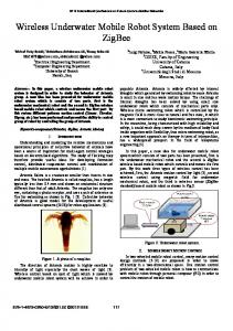
B.2. Adapter In order to provide a media-independent agent communication mechanism, adapters are necessary. Adapters provide a uniform interface to agent, regardless of the particular transport used. The transport can be a bus driver for software agent, special bus macros defined in Xilinx FPGA for hardware agent, or other high-level communication protocols, such as UDP, or low-level bus driver, such as Ethernet, for multi-robot systems connected by a network. When a message is sent to an agent (either software or hardware), the agent passes the message buffer to the adapter. The adapter sends data to the agent by way of the supported transport. Similarly, when a message is received from an agent, an adapter reconstructs a message buffer from the incoming data and sends buffer to the agent. V. A SELF-RECONFIGURABLE PLATFORM Since Vertex Pro-II FPGA is adopted as our protocol platform, the internal reconfiguration access port (ICAP) in Vertex Pro II FPGA makes the self-reconfiguration possible. A novel self-reconfiguration framework is proposed in this section. The goal of this framework is to provide a flexible method for implementing field self-reconfiguration while minimizing both system hardware and required configuration data, and reducing the reconfiguration time. As shown in Fig. 2, the fixed logic includes common fixed logic circuits, ICAP, configuration controller, multiple dual-port block RAMs (BRAMs), embedded processors, and external memory. The embedded processor provides intelligent control of device reconfiguration at runtime. The embedded processor communicates with FPGA logic through IBM-designed CoreConnect bus architecture. The DDR external memory is connected to the processor through process local bus (PLB bus). The fixed logic part is located the right-most columns because ICAP in Vertex II Pro FPGA is located at the lowerright corner while the reconfigurable logic part is located on the left-side columns. The configuration controller uses the ICAP to reconfigure the reconfigurable logic parts. The dualport characteristics allow the BRAM to be accessed from different clock domains on each side. In this selfreconfiguration platform, one port is accessed from the configuration controller, while the other port is accessed from the reconfiguration logic part. This makes the BRAMs act like a shared memory between the processor and reconfiguration
3371
logic parts, which can be further applied as buffers to reduce the reconfiguration latency. I/O Interface
common fixed logic circuits Embedded processors
ICAP Reconfigurable logic
Configuration control ler
PLB Bus
BRAMs Fixed Fixedlogic Logic
DDR (External memory)
CoreConnect Bus
Bus Micros
Fig. 2: A self-reconfiguration platform
Usually, there are two trigger conditions for the reconfiguration, one is from bottom-up, and the other is from top-down. The bottom-up method is through event interrupts invoked by the sensor agents. The top-down method is that the processor makes the decision due to the input information from sensor management agent. Both methods are applied in our platform. Another benefit from this self-reconfiguration platform is that the multi-agent communication mechanism can easily take advantage of the shared memory feature provided in this platform. Due to the dual-port characteristics of the BRAM, the software agents can send messages to BRAM through configuration controller, while the hardware agents can access their own message queues directly from the same BRAM. VI. A MULTI-AGENT-BASED MOBILE ROBOT SYSTEM An example of a multi-agent-based mobile robot system architecture is presented in Fig. 3, where each agent is described as followings. Processing Agents Sensor Agents Sensor Agents
External Environment
request from client agents to perform some service, and usually return a reply. The request and reply are made in the form of specific message format, which is application dependent. • When the workload or external environment changes or some emergency happens, such as sensor failure, it is necessary to send events to the corresponding agents through the message queues. In this bottom-up mode, all of the corresponding agents must register for the event. After receiving the event, the agents take actions to adapt to new changes.
Sensor Agents
Sensor Fusion Agent
Global Path Planning Agent Obstacle Avoidance Agent
Actuator Agents Actuator Agents
Actuator Agents
Actuator Manager Agent
Emergency Stop Agent Human-Robot Interface Agent
Fig. 3: Multi-agent based system architecture for mobile robots
Each Sensor agent itself is designed as one individual agent who is supposed to acquire some specific information from the external environment. One mobile robot system can have multiple sensor systems. To improve the fault tolerance of a robot system, sensor redundancy is required, which means that more than one sensor for the same functionalities are installed
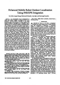
in the system. Usually one works as the active part, the other one works as standby. All of the sensor agents work parallel and independently. Sensor fusion agent analyzes the sensor information acquired by all of the sensor agents, fuse the sensor data if necessary, and send the fused sensor data to the higher-level processing agents Global path planning agent plans an optimized path for the robot to navigate across the global environment given a starting point and a destination point. Obstacle avoidance agent detours the robot when there are obstacles in the way to prevent the robot hitting the obstacle. Actuator management agent receives requests from processing agents, and distributes the control commands to individual actuator agents. Human-robot interface agent receives the events or processed environmental information from sensor fusion agents, and then sends corresponding commands to the robot. Emergency strop agent usually takes commands from human and sends request to actuator manager agent to stop the robot. According to the hardware/software co-design technology, the hardware and software agents are partitioned as the follows: the sensor agents, sensor fusion agent, actuator management agent, and actuator agents are configured in hardware on FPGA, while all of the processing agents, including path planning, obstacle avoidance, emergency stop, and humanrobot interface agents are implemented in software on embedded processor core. Based on the above multi-agent architecture, when a mobile robot navigates to different environments or sensors encounter some malfunctions, only affected sensor agents need to be reconfigured, while the other agents will continue their own tasks without any influence. The reconfiguration can be either triggered by the sensor agents by invoking a interrupt to processor, or by the processor itself based on its data checking algorithm. VII. EXPERIMENAL RESULTS To evaluate the performance of the proposed reconfigurable SOC-based architecture, a real-world robot, Pioneer 3DX mobile robot as shown in Fig. 4(a), is adopted as our platform in the experiment. The on-board sensors of this robot system include one CCD camera, two sonar rings (front and back), one laser rangefinder, and encoder odometry for dead reckoning position estimation, The Xilinx ML310 embedded development platform, as shown in Fig.4(b), is attached to the robot as an on-board processor. The ML310 offers designers a Virtex-II Pro XC2VP30-based embedded platform. It provides 30k logic cells, over 2,400kb BRAM, and dual PPC405 processors, as well as 256M DDR memory, multiple PCI slots, and standard PC I/O ports. Virtex II devices feature a regular architecture that comprises an array of CLBs surrounded by programmable IOBs, all interconnected by a rich hierarchy of fast, versatile routing resources. By implementing the self-reconfiguration architecture on FPGA, we assume that all of the possible plans of each sensor in terms of different sensor inputs are pre-defined and listed in the external DDR memory to ensure the performance. At 3372
starting time, a full configuration of the chip resources is required. During the run time, when the reconfiguration process is triggered either by the event interrupts from the sensor agents or by the embedded processor via the information checking, the embedded processor communicate with the configuration controller via the CoreConnect bus, then the configuration controller informs the ICAP to download the corresponding list of plans of the affected hardware agents to the FPGA configuration memory.
(a)
(b)
Fig. 4: (a) Pioneer 3DX mobile robot; (b) Xilinx ML310 embedded development platform
For the bottom-up trigger condition, the threshold values are set for each sensor. To prevent the “jitter” behavior due to the frequent reconfiguration, the reconfiguration of sensors will only take place when the input sensor values can not meet the minimum requirement of the sensor resolution for 5 sampling periods. There are some static registers located in BRAM to save the sensor status information. The sensor fusion agent will check the sensor status on those registers before it fuses the sensor information so that only the activated sensor data will be fused. The images acquired by the camera system are processed by hardware agents and only the featured information, such as whether a target is being detected or not, will be sent to the sensor fusion agent instead of extensive video and image information, which naturally leads to the simplification and efficiency of the communication. The real world experimental scenarios are shown in Fig. 5. The mobile robot (red circle) needs to navigate itself from one starting point at room B with dark illumination to the destination point at room A with good illumination while searching a target (green) on its way, where the target can be distributed randomly in room A. The map of two office rooms is given to the robot, where the obstacles (blue) randomly scattered at both rooms are not provided in the map. Starting point
Robot
Destination point
obstacle
room A
=
room B obstacle
target
Fig. 5: The navigation environment
For the hw/sw co-design approach, when the robot is in room B, the images captured by camera system are not usable for
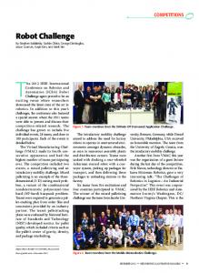
target detection, the vision sensor agent will be reconfigured as pass-though mode without processing any input information to save power consumption, and set the sensor status as invalid. Therefore, the sensor fusion agent will ignore the vision information. As long as the robot enters room A, the images become usable, the vision sensor agent will be reconfigured to process the image, and the sensor status will be set up as valid. Then the image information will be taken by the fusion agent. The wavefront path planner is applied as our global path planner and the Vector Field Histogram Plus local navigation method by Ulrich and Borenstein [18] is used as the underlying obstacle avoidance algorithm. Five configurations with different target locations in room A and different obstacles distributed in room B are designed in the above environment. 10 runs have been conducted on each configuration for both hardware/software and software-only approaches. The average navigation time of experimental results are shown in Fig. 6.
Average Navigation Time (minutes)
Average Navigation Time 25 20 15
hw/sw
10
sw-only
5 0 1
2
3
4
5
Configurations
Fig. 6: Average navigation time comparison for real-world experiments
It can be seen from Fig. 6 that there is a dramatic decrease in average navigation time in a dynamic environment with HW/SW co-design comparing with SW-only approach. The hw/sw approach increases the speed of action and reaction to dynamic environment because it makes decisions much faster than the software competitors. Another reason for the speedup is because hardware responds favorably to dynamic changes during runtime due to its parallel structures. Since only the simple color-based target detection is applied in our experiment, we didn’t take fully advantage of the proposed hw/sw architecture. For the more complex visionbased robots, such as service robots, the overall system responsiveness should be improved significantly using the proposed platform because the vision-related algorithms are extensive time consuming with software-only approach. VIII. CONCLUSION The major contributions of this paper includes: (a) propose an innovative multi-agent based architecture framework by which a unified hardware/software co-design methodology is applied on a configurable SOC to improve the system performance; (b) present a unified transport-independent communication mechanism for multi-agent systems, where an ODMP communication protocol is proposed; (c) establish a self-reconfiguration platform where the configuration control logic is located inside the FPGA logic array and is controlled
3373
by embedded processor core. (d) A real-time system example, a mobile robot, has been applied to evaluate the proposed embedded platform for its feasibility and efficiency. In our future work, we will apply the proposed hw/sw architecture to the robots requiring more computation extensive image and video processing algorithm to improve the overall system performance. REFERENCES [1] V. Gafni, “Robots: a real-time systems architectural style”, In Proc 7th European software engineering conference, pages 57-74, Toulouse, 1999. [2] J. Almeida, M. Wegdam, M. Sinderen, and L. Nieuwenhuis, “Transparent Dynamic Reconfigurable for CORBA”, Proceeding of the 3rd International Symposium on Distributed Objects & Applications (DOA 2001), Sept. 17-20, 2001, Rome, Italy. [3] J. Cobleigh et al, “Containment units: a hierarchically composable architecture for adaptive systems”, ACM SIGSOFT Software Engineering Notes, 27(6):159-165, November 2002. [4] B. MacDonald, B. Hsieh, and I. Warren, “Design for Dynamic Reconfiguration for Robot Software”, 2nd International Conference on Autonomous Robots and Agents, December 13-15, 2004, Palmerston North, New Zealand. [5] D. Stewart, R. Volpe, and P. Khosla, “Design of Dynamically Reconfigurable Real-Time Software Using Port-Based Objects”, IEEE Trans. On Software Engineering, vol. 23, no. 12, December 1997. [6] E. Yoshida, S. Murata, A. Kamimura, K. Tomita, H. Kurokawa, and S. Kokaji, “Self-reconfiguration modular robots – hardware and software development in aist”, In Proceedings, IEEE International Conference on Robotics, Intelligent Systems and Signal Processing, Volume 1, pages 339-346, October 8-13, 2003. [7] S. Patterson, K. Knowles, and B. E. Bishop, “Toward MagneticallyCoupled Reconfigurable Modular Robots”, Processing of IEEE International Conference on Robotics and Automation, New Orleans, LA, April 2004. [8] J. Villascnor and W.H. Mangionc-Smith, “Configurable computing”, Scientific American, no. 6, 1997. [9] S. M. Scalcra and J.R. Vazques, “The design and implementation of a context switching FPGA”, IEEE Symposium on FPGAs for Custom Computing Machines, 1998, pp. 78-85. [10] L. Sckanina and R. Ruzicka, ‘Design of the special fast reconfigurable chip using common FPGA”, in Proc. Of Design and Diagnostics of Electronic Circuits and Systems – IEEE DDECS’2000, 2000, pp.161-168. [11] B. Blodget, P. James-Roxby, E. Keller, S. McMillan, P. Sundararajan, “A self-reconfiguring platform, Proceeding of the 13th International Conference on Field Programmable Logic and Applications (FPL’03), pp. 565-574, 2003. [12] R. Fong, S. Harper, P. Athanas, “A versatile framework for FPGA field updates: an application of partial self-reconfiguration”, Proceedings of the 14th IEEE International Workshop on Rapid Systems Prototyping (RSP’03), 2003. [13] Y. Meng, A Dynamic Self-Reconfigurable Mobile Robot Navigation System, IEEE/ASME International Conference on Advanced Intelligent Mechatronics (AIM 2005), Monterey, California, USA, July 24-28, 2005. [14] Agent-Oriented Software Pty Ltd, JACK Manual (v4.1), www.agentoriented.com, 2003. [15] M. d’Inverno, D. Kinny, M. Luck, and M. Wooldridge, “A formal specification of dMARS”, Proceedings of the 4th International Workshop on Agent Theories, Architecture, and Language, vol. 1365 of LNAI, pg. 155-177, Berlin, 1998. [16] Y. Labrou and T. Finin, “A semantics approach for KQML – a general purpose communication language for software agents”, Third International Conference on Information and Knowledge Management (CIKM’94), 1994. [17] O’Brien, P and Nicol, R, “FIPA - Towards a Standard for Software Agents”, BT Technology Journal, Vol.16:3, pages 51-59, 1998. [18] I. Ulrich and J. Borenstein, “VFH+: Reliable Obstacle Avoidance for Fast Mobile Robots”, in Proceedings of the International Conference on Robotics and Automation (ICRA’98), Belgium, May 1998.