Ying Yi, Wei Han, Xin Zhao, Ahmet T. Erdogan and Tughrul Arslan. University of Edinburgh, The King's Buildings, Mayfield Road, Edinburgh, EH9 3JL, UK.
An ILP Formulation for Task Mapping and Scheduling on Multi-core Architectures Ying Yi, Wei Han, Xin Zhao, Ahmet T. Erdogan and Tughrul Arslan University of Edinburgh, The King's Buildings, Mayfield Road, Edinburgh, EH9 3JL, UK Abstract-Multi-core architectures are increasingly being adopted in the design of emerging complex embedded systems. Key issues of designing such systems are on-chip interconnects, memory architecture, and task mapping and scheduling. This paper presents an integer linear programming formulation for the task mapping and scheduling problem. The technique incorporates profiling-driven loop level task partitioning, task transformations, functional pipelining, and memory architecture aware data mapping to reduce system execution time. Experiments are conducted to evaluate the technique by implementing a series of DSP applications on several multi-core architectures based on dynamically reconfigurable processor cores. The results demonstrate that the proposed technique is able to generate high-quality mappings of realistic applications on the target multi-core architecture, achieving up to 1.3x parallel efficiency by employing only two dynamically reconfigurable processor cores.
I. INTRODUCTION An important trend in embedded systems is the use of multi-core architectures to meet application’s functional and performance requirements. Multi-core designs offer high performance and flexibility, at the same time promise low-cost and power-efficient implementations. However, the semiconductor industry is still facing several other technological challenges with multi-core systems. Important issues in multi-core designs are the communication infrastructure, memory architecture, and task mapping and scheduling. In multi-core architectures, the performance of the entire system is affected by the execution order of tasks and communications. It is well known that task mapping and task scheduling are highly inter-dependent. Therefore the two issues need to be handled together in order to obtain efficient mapping and scheduling. Dynamic reconfigurable (DR) processor combines the flexibility of FPGAs with the programmability found in general purpose processors (CPUs/DSPs) in a unified and easy programming environment. It is a strong candidate for multi-core systems. In our proposed embedded multi-core platform which has several DR processors [1], the shared memory heavily affects the execution time and power consumption. The time of data transmission between different processors must be considered during scheduling such that the design result can conform to the real situation. In addition, in order to meet the system throughput constraints, the design is pipelined to construct more efficient architectures. Pipelining divides the design into concurrently executing stages, thus increasing the throughput. In multi-core architectures all parallel tasks in an application have the potential to be executed simultaneously. However the number of such tasks may exceed the number of available processors. Therefore task mapping is required to
978-3-9810801-5-5/DATE09 © 2009 EDAA
assign the parallel tasks to the available processors. In the past, task merging and task replication have been proposed with the goal of re-allocating tasks when performance bottlenecks are met. Since task merging requires more local memory and task replication needs more processors to implement the same task [2], a multi-core architecture which does not feature sufficient memory and processors will severely limit the available mapping options using the existing methodology. Application development on multi-core architectures requires the designer, or automated tool, to divide tasks between available processors and to determine data mappings for the required memory elements. A SystemC-based simulation framework for mapping an application to a platform and evaluating its performance has been presented in [3]. The authors in [4, 5] have introduced scheduling and mapping parallel applications onto an MPSoC platform. Mapping solutions for bus-based and NoC-based MPSoCs have been described in [6] and [7]. Some automated system-level mapping techniques for application development on network processors have also been proposed [8]. This paper addresses the problem of automated application mapping and scheduling on DR processor based multi-core architectures. An Integer Linear Program (ILP) based approach is proposed for loop level task partitioning, task mapping and pipelined scheduling while taking the communication time into account for embedded applications. The efficacy of the technique is demonstrated by a series of DSP applications. The paper is organized as follows: Section 2 introduces the target DR processor as well as the target multi-core architecture. Section 3 describes the task mapping methodology. Section 4 gives a more detailed description of the problem addressed in this paper. Section 5 describes the proposed ILP based approach to solve the problem. The experimental results are given in section 6 followed by conclusions in section 7. II. TARGET MULTI-CORE ARCHITECURE Some applications demand a closer interconnection between the participating processors to achieve the required performance. Such a communication can be realised using distributed shared register files. The target multi-core platform is designed for DSP applications, which typically have intensive computations and a stream of input data. The architecture described in a previous work [2] consists of a selectable number of DR processors, which communicate with a shared memory through a full crossbar network. This architecture has been extended and modified by incorporating the shared register file into the system memory architecture in order to support the loop level parallelism proposed in this
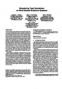
paper. The target multi-core architecture is based on a recently introduced DR processor architecture [9]. The DR processor offers comparable computation performance to leading DSP processors with a significant reduction in power consumption [1]. It contains an array of instruction-set functional units connected by a programmable interconnection. The DR processor is realised using an array of Instruction-Cells (ICs) that is reconfigured every processor cycle to map data-paths consisting of both dependent and independent instructions. The salient characteristics of the DR processor are that it is able to be fully customisable at design stage and can be set according to application requirements. All instruction cells in the DR processor can be connected to the entire shared memory or register file through interface cells. This scheme allows all possible connections between the instruction cells and the shared memory elements, but with a reduced multi-core interconnection complexity. The existing DR processor tool-flow gives full support by providing all the required files for the ILP model, which include a machine description file, a static profiling file, and a task graph (control data dependent graph). III. PROPOSED MAPPING FLOW Many DSP algorithms target streaming based applications and need to operate in real-time: the DSP application must read input data, process it, and write processed results out before the next input data is ready. A key concern in a DSP system is maintaining real-time execution. It is necessary to pipeline the application into concurrently executing stages to meet the throughput constraints of these systems. The implementation of DSP applications on a multi-core architecture mainly involves partitioning, mapping and scheduling the application tasks onto the processors as well as specifying data mapping and data transmission between these processors. The partitioning, mapping and scheduling of tasks are complex optimisation problems, which need to be solved simultaneously to maximise the throughput. In addition, the data communication time between different processors must also be taken into account during task mapping and scheduling to maximise the system throughput. The proposed mapping flow allows the designer to explore the application implementations on the target architecture platform as shown in Fig. 1. This paper mainly focuses on the automatic mapping. An ILP-based approach is proposed for loop level task partitioning, task mapping, and pipelined scheduling, while taking the data communication time into account for embedded applications targeted on the multi-core platform. During the process of task partitioning and task mapping, the estimation of execution-time for the different tasks as well as for transferring the data between processors is required. It is also necessary to schedule the execution order of these pipelined tasks to improve the system performance. The execution time of a task can be obtained from profiling file generated by the single DR simulator. The mapping flow starts from the description of an application in standard sequential C code which is then optimised and profiled for a single DR
Fig.1: Mapping methodology
processor implementation. Application developers can use the generated task mapping and scheduling information and a task-level interface (TLI) to build multi-core application code. A TLI interface is an application programming interface. It can be used for developing parallel application program on multi-core architectures. The TLI interface provides services for inter-task communication and task allocation. It must allow parallelism and communication to be made explicit to enable mapping to multi-core architectures. For example, if a task uses an abstract interface for synchronization with other tasks, it hides the detailed implementation of the synchronization. The multi-core application code is compiled and simulated with the single DR processor. The single DR processor simulator generates an execution trace file, which is used as an input to the multi-core simulator (MRPSIM) [9]. MRPSIM is a trace-driven simulator which can correctly and efficiently simulate the run-time multi-core environment, allowing the throughput of the modelled system to be measured. The proposed mapping approach also takes into account the task graph (control data flow graph), the multi-core architecture model, and static profiling file. The static profiling information contains the timing characteristics for each task and the access frequency for the various data items. The multi-core architecture model, also called the machine description file, consists of the set of processors and the set of memory. These are used for mapping tasks to available processors as well as mapping various data items to memory architecture. Our solution consists of dividing the problem into two stages and solving each consecutively. The first stage assigns and schedules tasks to processors, assuming an idealistic memory mapping, where all data items are mapped to the fastest possible level of memory, ignoring memory capacities. The ILP formulation of this stage includes task merging, task replication, and loop level splitting and fusion. The task merging combines several tasks into a single task that performs tasks in an efficient order. This technique reduces the number of required processors, but needs more local instruction and data memories. Task replication assigns the same task to
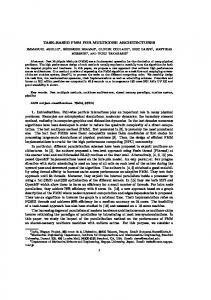
several processors such that all instances of the task are executed in parallel. Therefore, task replication needs more processors to implement an application and also more global memory to save the shared data. A new mapping approach is needed when the workload among the processors is unbalanced and task replication cannot be used due to the limited number of available processors. The new mapping approach divides the tasks at basic block level instead of at the function level in order to explore the loop level parallelism. In tasks and communications scheduling process, in order to consider data dependency between tasks and resolve resource contention, we model the scheduling problem with data dependency constraints between tasks, constraints that represent resource contention. The task graph generated by the DR compiler provides basic block and function level control and data dependency. A task is defined as a small procedure, function or just a basic block. The start task has no incoming arcs, and end (leaf) task has no outgoing arcs. The ILP model with and without functional pipelining is proposed in [10] but can only handle this in a restricted way. The restriction is that the first computation of a task in the (i+1)-th iteration is only possible if all leaf tasks are finished in the i-th iteration. This limitation will generate inefficient solution for some task graphs, which is illustrated in Fig.2. Fig. 2(a) gives a task graph of a small example. The time interval between two successive iterations of the algorithm is called latency (LT). The overall computation time (OCT) of n frames without functional pipelining is equal to n ⋅ OET , where OET is the overall execution time for one frame. The method given in [10] provides a longer latency (LT=OET) which is shown in Fig. 2(b). Our model removes the above limitation, which results in more efficient mapping and scheduling shown in Fig. 2(c). This approach will be illustrated in detail in the following two sections. processor LT Ti
Pm
Tk
Ti
Pk
Tj
Tk Tj
time
(b) with OCT = OET + LT = 2*OET
processor LT
Tk (a) task graph
Ti
Tj
Pm Pk
Ti
Ti Tj
Tk
Tk
Tj
time
(c) with OCT = OET + LT < 2*OET
Fig.2. Advantage of functional pipelining
The second stage performs a mapping of data items to memory architecture and explores the memory architecture for minimizing memory access latencies. Each DR processor can access three types of memory: (a) the shared multi-bank register file, (b) local memory, and (c) shared memory. The local memories are private to a processor and cannot be accessed by other processors. Thus, shared data items, accessed by tasks assigned to different processors, cannot be mapped to these memories. Instead, they are mapped either to the shared multi-bank register file or to shared memory, which can be accessed by the different processors. Here, we adopted a similar ILP formulation given in [8] for this stage.
IV. MAPPING HEURISTICS AND PROBLEM DEFINITION In this section, we define the problem of task mapping and scheduling for DR processor based multi-core architectures. Given a task graph, a multi-core target architecture with its parameters, and a mapping of tasks and data on the target architecture including processors and memory, the problem is to find a mapping and scheduling of task executions and communication transactions which yields minimum execution time of the task graph on the target architecture. To solve the problem, target architecture, task and applications definitions are presented. Then, an ILP formulation or a heuristic algorithm is introduced to map and schedule tasks and communications.
A. Architecture Definition A target multi-core architecture is specified by the set of processors P and the set of memory elements M. Each processor p is a 2-tuple p=(pid, pcm) where pid is the processor identifier and pcm is the instruction memory of the processor. Each memory element m is given by a 4-tuple m=(mid, mc, mt, nm), where mid is the memory element identifier, mc is the capacity of the memory, mt is the time required to access the memory, and nm is the type of the memory (shared memory, local memory, or shared register file). The target architecture model based on the above specification is extracted from the multi-core architecture model file. B. Application Definition An application is represented by the hierarchical task graph, which is an acyclic directed graph G=, where the vertex set V is a set of tasks and the edge set E is communication edges. Each small procedure or a basic block is defined as a task which is a 5-tuple t=(tid, pt, tc, td, nd) where tid is the task identifier, pt is the task execution time excluding memory conflicting accesses delay, tc is the total instruction memory required by the task, td is the amount of memory required to store the local data of the task, and nd is the number of times the local data item is accessed. Each communication edge is described with the form (mid, sid, sd, nsd), where mid is the master task identifier, sid is the slave task identifier, sd is the amount of memory required to store the shared data between two tasks, and nsd is the number of times the shared data item is accessed. The application task model is profiled to obtain timing characteristics for each task and the access frequency for the various data items. The objective is to map and obtain a static mapping and pipelined scheduling of the task graph on the target multi-core architecture such that the throughput is maximized while satisfying performance constraints. The result of the mapping procedure is the decision which tasks run on which processors at what time. V. ILP FORMULATIONS In this section, we present the ILP formulation that gives an optimal solution for the problem described in section 4. Our solution is based on the mapping strategy given in [8] and extended the ILP model with pipelined scheduling. The ILP model supports task merging and task replication. It means that
a task may be performed on several processors in order to exploit more parallelism. We assume that each processor has its own local memory and only one task can be executed at a time by one processor. Each DR processor can execute all tasks. Tasks on different processors can be executed in parallel. The ILP formulation incorporates task merging and replication by first assigning processes into batches, which are then assigned or replicated to processors [8]. Now, a short summary of the abbreviation is given. N represents the number of tasks; M is the number of available DR processors. T set of tasks T = {T1, T2, … , Tn} L set of the end (leaf) tasks L ⊂ T S set of the start tasks S ⊂ T P set of processors P = {P1, P2, … , Pm} B set of batches B = {B1, B2, … , Bl} {l= min(m, n)} Constants and variables used in the ILP formulation: sij ,k start time of task Ti on processor Pj in the k - th iteration communication time for sending data from Ti to Ti '
Cii ',k
⎧1 rlj = ⎨ ⎩0 d ii ' j
⎧ ⎪1 =⎨ ⎪0 ⎩
j∈P
•
•
task Ti is assigned to batch l otherwise batch Bl is assigned to processor j otherwise
batch Bl is replicated on j processors otherwise tasks Ti and Ti ' are allocated on the same processor Pj , and Ti starts execution before task Ti '
the processor Pj that extectue task Ti providing ⎧ ⎪ ⎪1 data for any task Ti ' with (i,i ' ) ∈ E; the two tasks x ji = ⎨ are allocated on the differnt processors ⎪ ⎪ 0 otherwise ⎩
∀(i, i ') ∈ E, ∀j, j ' ∈ P, j ≠ j ' :
The objective function used in the ILP formulation: minimise (k1 • TP + k2 • LT )
il
•
The start time of all tasks have to be positive. ∀ i ∈ T , ∀ j ∈ P : sij , k ≥ 0
∀n
•
j ∈P
Each processor must be assigned to a single batch. ∀j ∈ P : ∑ blj = 1
(3)
l ∈B
•
A batch must be assigned to one or more processors only
(9.2) (10)
•
If processor Pj executes task Ti ( x ji = 1 ), then task Ti is assigned one batch and this batch is allocated to processor Pj. ∀i ∈ T , ∀j ∈ P : x ji ≤ ∑ til ⋅ blj (11)
•
To minimise the OCT it is necessary to begin the start task in iteration (i+1) as soon as possible. Each task without replication should be allocated to the same processor in each iteration. In addition, it is required that each start task of (i+1)-th iteration can only start on a
(1)
A batch is replicated on n processors, and then exactly n processors must execute that batch. (2) ∀l ∈ B : ∑ n ⋅ rln = ∑ blj
(8.2)
Two independent tasks must not be executed on the same processor at the same time. i.e., Task Ti is executed either before task Ti’ ( dii ' j = 1 ) (9.1) or after task Ti’ ( dii ' j = 0 ) (9.1) on processor Pj. ∀(i, i ') ∉ E , ∀j ∈ P : (9.1) sij , k + pt (i) ≤ si ' j ,k + (3 − tij − ti ' j − dii ' j ) ⋅ MAX _ VAL
l∈ B
•
(8.1)
•
si ' j ,k + pt (i ') ≤ sij ,k + (2 − tij − ti ' j + dii ' j ) ⋅ MAX _ VAL
Constraints used in the ILP formulation: • Every task must be assigned to a single batch; =1
A data dependency constraint exists between the two tasks Ti and Ti’ if there is an edge between two tasks Ti and Ti’ in the task graph G(V, E). The execution of task Ti has to be finished before the execution of Ti’ if they are on the same processor [constraint (8.1)]. When the tasks are allocated to different processors, Ti’ can start cii’ time units after Ti has finished [constraint (8.2)]. Since the ILP model supports task replication, a task can be allocated to several processors. We need to consider all possible task allocations of replicated tasks on all processors and also need to know which processor that executes task Ti provides the data for task Ti’. This is done by variable xji given in the beginning of section.
sij ,k + pt(i) + Cii ',k ≤ si ' j ',k + (2 − ti ' j ' + tij ' − x ji ) ⋅ MAX _ VAL
An objective function depending on the system throughput (TP) and the latency (LT) need to be minimised. TP and LT are continuous variables in our ILP model. The objective function is given below. The weights k1 and k2 of the costs TP and LT can be tuned by the designer.
∑t
The throughput is equal to the maximum effective time over all batches. r ∀l ∈ B : TP ≥ ∑ ln ∑ til ⋅ pt (i ) (6) ∀n n i∈T The finishing time of each leaf task is less than or equal to OET ∀i ∈ L, ∀j ∈ P : sij,0 + pt(i) ≤ OET + (1− til ⋅ blj ) ⋅ MAX _VAL (7)
∀ (i , i ') ∈ E , ∀ j ∈ P : sij , k + pt (i ) ≤ si ' j , k + (2 − tij − ti ' j ) ⋅ MAX _ VAL
otherwise
∀i ∈ T :
i∈T
where MAX_VAL is a very large value. The instruction size of all the tasks assigned to a batch cannot exceed the size of the available instruction memory of the processor. ∀l ∈ B, ∀j ∈ P : ∑ til ⋅ tc(i ) ≤ pcm( j ) (5) i∈T
•
•
in the k - th iteration, if there is (i, i ') ∈ E;
⎧1 til = ⎨ ⎩0 ⎧1 blj = ⎨ ⎩0
if there is at least one processor assigned to the batch. Otherwise, the batch can be ignored. ∀l ∈ B : ∑ blj ⋅ MAX _ VAL ≥∑ til (4)
l∈B
processor after this task’s i-th iteration is finished on this processor. If a task has been replicated, there is no constraint between the different iterations. The latency time is affected by the first start task of the i-th iteration and the first task of the (i+1)-th iteration. ∀i ∈ S, ∀j ∈ P : sij ,k + LT ≤ sij,k +1 + (1− til ⋅ blj ) ⋅ MAX _VAL (12) VI. CASE STUDY: LOOP LEVEL PARALLELISM
The following section demonstrates the effectiveness of the proposed mapping methodology using a series of DSP applications. The application set includes (1) a 64-tap Finite Impulse Response (FIR) filter, (2) an Advanced Encryption Standard (AES) application, (3) a Fast Fourier Transform (FFT) application, (4) a smoothing and edging image processing application for a 256*256 grayscale image, and (5) a Freeman demosaicing application for a 1138*850 RGB image. Some compiler optimization techniques have been adopted in our multi-core mapping models, which includes loop splitting and loop fusion. Loop splitting attempts to simplify a loop or eliminate dependencies by breaking it into multiple loops which have the same bodies but iterate over different contiguous portions of the index range. Loop fusion (loop combining) attempts to reduce loop overhead. When two adjacent loops iterate the same number of times, their bodies can be combined as long as they make no reference to each other's data. Let us consider the application of the 64-point 6-stages radix-2 FFT to demonstrate loop splitting. Mapping solution is not only dependent on the strategy but also on the architecture design. The multi-core FFT implementation is mainly affected by the number of processors and the shared register file size in the multi-core architecture. To demonstrate the proposed mapping methodology, the FFT application is mapped to several different multi-core architectures including: (a) limited processor cores with limited shared register banks, (b) limited processor cores with sufficient shared register banks, and (c) sufficient processor cores with sufficient shared register banks. The FFT-I application is mapped onto a multi-core architecture with two processor cores, sufficient local and shared memories and an 32*32 shared register file shown in Table 3. The most time consuming part of the application is the TABLE I.
A CODE EXAMPLE OF LOOP SPLITTING
for (stage=0; stage