An Overview of MAC Protocols with Directional Antennas in Wireless ad hoc Networks Hongning Dai and Kam-Wing Ng The Chinese University of Hong Kong Department of Computer Science and Engineering Shatin, N.T. Hong Kong {hndai,kwng}@cse.cuhk.edu.hk Abstract Although directional antennas have been used in mobile communications systems for quite a long time, realistic applications of directional or smart antennas in wireless ad hoc network have emerged just in recent years. Directional antennas provide numerous benefits, such as higher gains, increased transmission range and low interferences. Wireless medium access schemes play a crucial role in ensuring the efficient and fair sharing of wireless resources. Therefore there are many research work on mechanisms at the wireless medium access layer by using directional antennas. The new features of MAC with directional antennas can cause not only location dependent carrier sensing problems, which have appeared in omnidirectional wireless networks, but also novel issues related to directional antennas. In this paper, an introduction of directional antennas is given. We give a classification of the current wireless MAC protocols using directional antennas. We also present different MAC protocols and compare them. This survey discusses the challenges in the design of these MAC protocols.
Min-You Wu Shanghai Jiao Tong University CSE Department 1954 Hua Shan Road, Shanghai, P.R.China
[email protected]
less networks with omnidirectional antennas, such as hidden/exposed terminal [5], new challenging issues related to directivity have arisen when using directional antennas. The MAC protocols with directional antennas have been studied extensively in recent years. However, a summary work on these MAC schemes is rare. To the best of our knowledge, there is only one paper surveying this area [16], with an incomplete overview and imprecise classification of some recently proposed protocols. Moreover many protocols have given inaccurate descriptions of directional antennas. Clarifying the ambiguous models of directional antennas is also a prerequisite work. Therefore we survey the various MAC protocols using directional antennas and compare them on the basis of antenna types, properties of antennas, node mobility and performance issues, etc. Our work is confined to the medium access layer spanning relatively few other layers. This paper is organized as follows. First, we provide a brief introduction to directional antennas and their classification in Section 2. We then introduce the MAC issues caused by directional antennas in Section 3. Section 4 gives the classification of directional MAC protocols and describes them. We compare the protocols in Section 5. Section 6 summarizes our work.
1. Introduction 2 Unlike omnidirectional antennas, directional antennas can increase spatial reuse and provide higher gain and reduce interference by directing the radio beam towards a desired direction. Increasing spatial reuse and transmission range will enhance the network capacity [6]. To fully leverage the benefits that directional antennas can bring, well designed medium access control (MAC) protocols should be deployed. However, since multiple devices can access the airborne and broadcast wireless medium at the same time, the conflicts caused by simultaneous access can not be avoided. Besides the existing problems in wire-
2.1
Directional Antennas Classification of Directional Antennas
Different from omnidirectional antennas, which radiate or receive electromagnetic energy in all directions, directional antennas can be constructed to have certain preferential transmission and reception directions. There are two kinds of directional antennas [7]: traditional directional antennas and smart antenna systems. Unlike the traditional directional antennas, the smart antennas consist of not only a number of radiating elements but a combining/dividing
network and a control unit. The control unit is normally implemented by using a digital signal processor (DSP), which is the intelligence of the smart antenna. Smart antennas can be generally categorized as the following types [13][11]: • Switched beam antenna: The antenna system uses a linear RF network, called a Fixed Beam-forming Network (FBN) that combines M antenna elements to form up to M predetermined directional beams. This antenna allows the selection of signal from the desired direction. While providing increased spatial reuse, switched beam systems offer limited performance improvements because of the fixed beam patterns. • Adaptive array antenna: The signals are processed adaptively by a combining network and summed to create a steerable radiation pattern. The Direction of arrival (DoA) algorithm for signal reception is applied for signal transmission/reception and continuous tracking. Besides the capabilities to change antenna pattern dynamically to adjust to noise, interference and multipath, the antenna can also place nulls to the direction of the interferences and offer more comprehensive interference rejection. Similar to adaptive array antenna, the DoA algorithm is also used in dynamically phased array. Since null capability is not assumed, the phase array antenna is limited in interference suppression. The benefits derived from a smart antenna system include increased range, improved spatial reuse, multipath rejection, reduced interferences and enhanced capacity. In comparison, adaptive array technology currently offers more comprehensive interference suppression and require less hardware redundancy than switched beam systems. With cost-decreased adaptive array antenna arises in the market, more popular utilization of the systems will be.
2.2
Fundamental properties of directional antennas
2.2.1
The gain of antennas
The antenna radiates the time-averaged power in all directions. The gain of an antenna can be defined as U (θ, φ) G(θ, φ) = η Uave
The power gain G(θ, φ) of an antenna is the ratio of radiation intensity to average intensity over all directions. If no direction is specified, the gain usually means the maximum gain value over all directions. Due to the reciprocity, all the gain and radiation pattern characteristics are known to be the same for both transmission and reception [1]. 2.2.2
Radiation Pattern Models for Directional Antennas
An antenna pattern is the specification of the gain values in each direction in space, described as projections on the elevation and azimuth planes. It typically has a main lobe of peak gain and side lobes of smaller gains, which affect the normal transmission. In most cases, the more directional the antenna is, the higher the gain and the smaller the beamwidth will be. There are two common models for gain and patterns of directional antennas [7] [13]: Flat-top radiation pattern, which assumes that the gain is constant within the beamwidth and there are no side lobes. The antenna beam can be seen as a slice of a pie in shape. Cone+Sphere radiation pattern, which was proposed in [13]. The sphere accounts for the effects of sidelobes and the gain value inside the cone is constant. 2.2.3
Transmission and Reception Modes
Actually every antenna has four transmission and reception modes: omnidirectional transmission, omnidirectional reception, directional transmission and directional reception. If a receiver listens in directional mode, the maximum reception gain Gr will be reached. If a sender transmits in directional mode, the maximum transmission gain Gt will be reached. Thus, when a receiver listens in directional mode and a transmitter sends data also in directional mode, according to free space propagation theory [15], the required transmit power can be further reduced. Moreover, in that case, the communication range can be maximized with minimized interferences and the wireless network capacity can be greatly increased [6]. However, depending on the directivity of the beams, scheduling antenna beams to face each other at the same time is still challenging.
3
MAC Issues with Directional Antennas
(1)
where U (θ, φ) is the power density in direction (θ, φ), Uave is the average power density over all directions and η is the efficiency of the antenna. If the antenna transmits power equally in all directions, then U (θ, φ) will be equal to Uave , and the antenna is called isotropic. An isotropic antenna has a spherical pattern and is only used for analytical purpose.
3.1
Antenna patterns issues on MAC protocols
The various radiation patterns of different directional antenna affect the design of distinctive MAC protocols. An antenna pattern typically includes a main lobe with a peak gain and several side lobes of smaller gains. The side lobes
often interfere with normal transmission. Many current protocols approximate the side lobes as a sphere with a constant gain and the main lobe as a cone with a uniform gain [13]. Some proposals even simplify the antenna patterns as sectors without sidelobes. These coarse models may not be very appropriate for real life situations [14] Another important issue is the nulling capability of directional antennas. Most proposals published recently have not fully exploited the potential of the directional antennas to reduce the interferences and maximize SINR. In [10], a spatial null angle vector is used to modify the radiation pattern by placing nulls in appropriate directions. Singh et al. exploite the nulling ability of direction antennas in [17] [18] [19] and get remarkable performance improvements.
3.2
try in gain and unheard RTS/CTS. There also exists a directional exposed terminal problem. However, this problem can be solved by using DNAV (directional Network allocation Vector) [20] [4]. Using directional antenna can suppress the impact of the exposed terminal problem and improve utilization of the bandwidth. Another problem, deafness, has arised due to directional beamforming [3]. Briefly, deafness is caused when a transmitter fails to communicate to its intended receiver, because the receiver is beamformed towards a direction away from the transmitter . This problem may waste the network capacity and result in unfairness as well. Choudhury et al. [3] propose a tone based notification mechanism (ToneDMAC) which allows neighbors of a node to classify congestion from deafness and react appropriately.
Transmission range and power control 3.4
The increased transmission range by using directional antennas can help reducing the hops between the source and destination terminals and increasing the network connectivity by bridging the disjoint network partitions. In [4], Choudhury et al. attempte to extend the transmission range between the sender and the receiver to directionaldirectional connection. Korakis et al. fully exploite the range extension of directional antenna in [9]. Zhang et al. also propose a pure directional transmission and reception algorithm (DTRA) in [25]. The full usage of directional transmission and reception between two nodes brings out the challenges in the design of MAC protocols, such as neighbor discovery. When increasing the transmission range, new problems arise: the extended directional range will cause interferences among the nodes inside the coverage. In [21], Takai et al. present a reception range control method instead of transmission range control, therefore the extended communication will not interfere with ongoing communications. It adaptively controls the communication range by estimating dynamically changing local network density. This mechanism can dramatically improve the packet delivery ratio.
3.3
Location-dependent Carrier Sensing
In the case of omnidirectional antennas, only those nodes within the radius of the transmitter can detect the carrier on the channel. This location-dependent carrier sensing results in the hidden terminal, exposed terminal and capture problems [5]. The application of IEEE 802.11 DCF (RTS/CTS) scheme to wireless networks with directional antennas can induce new problems of location-dependent carrier sensing, such as new hidden terminal problem and the deafness problem that never happen with omnidirectional antennas[4]. The new hidden terminal problem arises due to asymme-
Neighbor location and neighbor discovery
Different from omnidirectional antennas, the knowledge of the neighbors’ angular location is critical for directional nodes. With the location information of the receiver, the transmitter can beamform its main lobe to the direction of the receiver and maximize the gain. The location information is also essential to mitigate the possible interferences caused by other neighbors. It is possible for a node to have the latest location information of its neighbors when it is equipped with a location determination hardware, such as a GPS receiver. However, in addition to the economic factors of GPS devices, the selflimitations of GPS devices have restrained the application of GPS devices from the wireless ad hoc networks. There are other methods to estimate the location of a node without using any additional hardware. These techniques typically use distance or angle measurements from some reference points and apply triangulation to locate the node. One of the representative methods is angle of arrival (AoA) measurements [20]. The main limitation for the AoA method is the possibility of error in estimating the directions caused by multipath reflections. Another significant problem is directional neighbor discovery. The hard problem in directional neighbor discovery is to determine where to point, and when to point the antenna for transmit or receive [14]. There are two kinds of directional discovery: informed discovery and non-informed discovery (blind discovery). In informed discovery, a node can get location information of other neighbors by AoA caching [20], maintaining a location table [9] or multi-hop routing [4]. Blind discovery is more useful than informed discovery, however, it is far more challenging. In [14], a synchronized TR-BF (transmit and receive beamforming) blind discovery mechanism is proposed. It is assumed that at a certain time, each node alter-
nates randomly between sending heartbeats in one direction and listening in the opposite direction for such heartbeats. After several rounds of location information exchanging, all the nodes can get locations of their neighbors. [25] proposes similar scanning neighbor discovery strategies based on synchronization. However, the existing blind methods assume strict synchronization on each node, which may require a common clock source, for instance GPS. [22] proposes direct-discovery algorithms and gossip-based algorithms in which nodes can discover their one-hop neighbors. Although the algorithms can work on asynchronous systems, they are not appropriate for mobile environments.
4
Classification of Directional MAC protocols
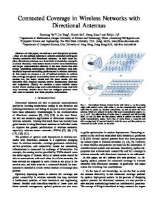
There are quite a few classifications based on different features of the protocols. In [16], Vilzmann et al. classify the directional MAC protocols according to whether a protocol is based on IEEE 802.11 or not. However, this classification is a little coarse, since some protocols from different categories are quite related to each other. For example, Smart-802.11b is based on Smart-Aloha , but they are classified into two different categories [18]. Figure 1 shows the classification of current directional MAC protocols. Directional medium access schemes can be divided into two main categories: random access and scheduling mechanisms. Random access based protocols can be further classified according to different collision avoidance approaches into: 1) pure-RTS/CTS protocols; 2) tone-based protocols; 3) other protocols using additional control packets.
MAC protocols by using directional antennas
Random Access Mechanism
Pure-RTS/CTS mechanisms
Tone-based mechanisms
Scheduling Mechanism
other control packets
Figure 1. Classification of directional MAC protocols
4.1
Random Access MAC protocols for directional antennas
4.1.1
pure-RTS/CTS protocols
One of the early protocols, Directional MAC (DMAC) [8] assumes that each node is equipped with multiple directional antennas. This protocol is revised based on the IEEE 802.11 MAC to accommodate directional antennas. In this scheme, one antenna or direction on a node will be ”blocked” when receiving RTS/CTS packets at that direction. But the other antennas of that node will be allowed to transmit since they are ”unblocked”. Nasipuri et al., proposes a directional antenna MAC protocol in [12]. This protocol assumes that it is not necessary to know each node’s location information. Each node is assumed to be equipped with M directional antennas, which have conical radiation patterns and cover an angle of 2π/M . Thus the M antennas in each node have a coverage of the entire plane. The scheme works in the following ways. Idle nodes are assumed to listen in all directions. Firstly, the source and destination nodes use omnidirectional RTS/CTS to build up the handshake. The sender and receiver estimate the location of each other by noting the antenna that received the maximum power of the RTS/CTS packets. Then they use the antennas facing each other to transmit data directionally. This protocol can be applied to mobile environments. The Directional Virtual Carrier Sensing (DVCS) scheme is used in mobile ad hoc wireless networks [20]. Each network node is assumed to have an electrically steerable antenna system, which can change the beamforms of the antenna dynamically. Each node will cache the estimated AoAs of its neighbors when it hears any signal, regardless of whether the signal is targeted at the node. When it has data to send, if location information of the destination node is available, it will beaform at that direction, otherwise it will send RTS omnidirectionally. Beam locking and unlocking mechanisms are used to maximize the received power and reduce signal distraction. The protocol also uses Directional Network Allocation Vector (DNAV) to maintain a unique timer. DNAV is a directional version of NAV (Network Allocation Vector) in IEEE 802.11, which reserves the channel for others only in a range of directions. The Multihop Medium Access Control (MMAC) protocol [4] builds on the Basic DMAC protocol, which originates from DMAC [8] and is similar to the DVCS proposed in [20]. Each node is assumed to be equipped with two separate antennas: an omnidirectional antenna and a steerable single beam antenna. MMAC attempts to exploit the extended transmission range of directional antennas, while achieving spatial reuse comparable to Basic DMAC. There are two kinds of neighbors: Direction-Omni (DO) Neighbors and Direction-Direction (DD) Neighbors. Firstly, the
node will try a DD link with the destination node and send a RTS frame in the direction of the destination. If it fails to receive a CTS from its receiver within a suitable timeout interval, it will initiate a multiple hops RTS forwarding along the DO-neighbor route to the destination. On receiving the RTS, the destination node will reply with a CTS by pointing its transmitting beam in the direction of the sender. Once the CTS is received, the DD link is formed and the directional transmission begins. Korakis et al. propose a Circular-DMAC protocol and attempt to fully exploit the benefits of directional antennas [9]. The authors assume each node is equipped with a switched beam antenna and there is no omnidirectional mode. They propose a circular directional RTS, which is transmitted consecutively until it scans all the area around the transmitter. Each node maintains a location table, which records the locations of other nodes that it has heard. In this paper, the DNAV mechanism is also used to combat the hidden terminal and deafness problems. Although, these mechanisms offer significant improvement over that of omnidirectional transmissions, the excess control packets caused by circular directional RTS will degrade performance. 4.1.2
Tone-based directional MAC protocols
The Dual Busy Tone Multiple Access with Directional Antennas (DBTMA/DA) [23] is a variation of DBTMA by using directional antennas. The switched beam directional antenna model is adopted in this paper. In addition to the directional transmission of RTC/CTS and data packets, a tiny busy tone is used to avoid collisions in a much finer grain with increased spatial reuse and channel capacity. Two busy tones: transmission busy tone and reception busy tone are assigned two separate single frequencies in the control channel. A node hearing a transmission/reception busy tone will defer receiving/transmitting, which alleviates both the hidden and exposed terminal problems. Choudhury et al. propose a Tone-based directional MAC (ToneDMAC) protocol to attack the deafness problem [3]. The authors also assume a switched beam antenna system. Different from DBTMA/DA in [23], which requires an additional transceiver since busy tones are transmitted with data simultaneously, the ToneDMAC needs only a single transceiver. The channel is divided into two sub-channels: a data channel and a narrow control channel. RTS/CTS, Data and ACK packets are transmitted on the data channel. The tones occupy the control channel. The neighbors of a node can recognize the node by its unique tone, which is determined by a tone frequency and a duration that are hash functions of the node’s identifier. In order to reach all the directional neighbors, the transmission power of the tones is increased to what can cover the range of directional transmissions. The increased range can silence the transmission
of neighbors, although the tone has a different frequency. Smart-Aloha [18] is a slightly modified version of the standard Slotted-Aloha protocol. Transmitters beamform towards their receivers and send a short (8-byte) pure sender-tone before transmitting a packet. The receivers (in omni-directional mode) run a DOA algorithm to identify the direction and then point the beam in the maximum received signal direction and forms nulls in other directions. If a packet is intended for the receiver, the packet will be accepted and an ACK will be replied. Otherwise, the receiver discards it and the sender enters backoff. The Smart-Aloha follows a Tone/Packet/ACK sequence. Smart-802.11b [18] is based on the IEEE 802.11b standard and the Smart-Aloha protocol. Smart-802.11 avoids collisions by using sender-tone and receiver-tone as well. Unlike Smart-Aloha, in Smart-802.11b, the transmitter waits for a receiver-tone and then sends a packet instead of sending data immediately following the sender-tone. It waits for the replying ACK from the receiver. If the sender does not receive the ACK, it will enter backoff like IEEE 802.11b. Different from RTC/CTS, both the sender-tone and receiver-tone are sent towards the receiver or sender without indicating the destination node, while RTS/CTS have their destination encapsulated in the packets. So in Smart-802.11b, a node may receive a packet that is not intended for it. Singh et al. also propose two other kinds of tone based MAC protocols in [17] and [19]. DOA-MAC [17] is a timeslotted protocol also based on the standard Slotted-Aloha. Each slot in DOA-MAC is divided into 3 minislots. In the first minislot, all the transmitters send a tone towards their intended receivers. The receivers point their beams towards the senders after running a DOA algorithm to determine the directions of the senders. Then the packets are transmitted in the second minislot. The receivers reply with ACKs within the last minislot. If the transmitter does not receive the ACK, it will retransmit the packets later. Tonebased 802.11b [19] is quite similar to DOA-MAC. Different from DOA-MAC, tone-based 802.11b is unslotted and uses sender-tone and receiver-tone instead of simple tone in DOA-MAC. These protocols based on busy tone do not attempt to combat the hidden terminal problem because the negative effect of hidden terminals can be minimized by exploiting nulls dynamically. 4.1.3
Other directional MAC protocols using additional control packets
Lal et al. [10] propose a MAC protocol exploiting Space Division Multiple Access (SDMA), which can improve the throughput of bottleneck nodes by synchronizing the packet receptions from other nodes. The scheme assumes that each node has only one adaptive array antenna sys-
tem. A receiver-initiated approach is proposed to achieve the time synchronization for receptions. The receiver polls all its neighbors by sending an omnidirectional Ready-toReceive (RTR) packet periodically. The intended senders will reply with a directional RTS packet, with directional CTS/DATA/ACK sequences following. Since the RTR packet is larger than the typical control packet size, it may result in extra overhead. From the simulation results, it is observed that when the load is low, the RTR-based protocol performs even worse than IEEE 802.11b with omnidirectional antennas. When the bottleneck of transmission is salient, this protocol performs much better than IEEE 802.11.
4.2
Scheduling MAC protocols for directional antennas
A distributed receiver-oriented multiple access (ROMA) protocol is proposed in [2]. This protocol leverages an antenna array, called multi-beam adaptive array (MBAA), which uses more complex DSP technologies than the directional antennas. The MBAA can form multiple beams for several simultaneous receptions or transmissions, with increasing the network capacity. All the nodes are assumed to be synchronized. In each time slot, the nodes in the network are equally divided into transmitters and receivers, which then couple together in pairs for the maximum throughput. ROMA allows both transmitters and receivers to use the directional mode, instead of requiring one end of the communication to stay in omnidirectional mode. ROMA achieves collision freedom for channel access using only two-hop topology information and gains improved efficiency. Zhang [25] [24] proposes a directional transmission and reception algorithm (DTRA) in wireless ad hoc networks. Each node is assumed to be equipped with a steerable antenna. In DTRA, time is divided into frames and each frame is split into 3 sub-frames. One sub-frame is used for neighbor discovery and 3-way handshaking during the period. Another sub-frame is devoted for two nodes to reconfirm their connection detected during neighbor discovery and to make data reservation. The final sub-frame is used for the actual data transmission. Similar to ROMA, all nodes are synchronized. A scanning for neighbors approach is used to exchange location information among the nodes. In this process, transmitters and receivers can exchange the messages for possible transmission in the next step by a 3-way handshaking algorithm. Reservation confirmation is quite like the 3-way handshaking process in neighbor discovery except for the different messages contents. Power control is also carried out during the processes of neighbor discovery, reservation and data transmission with little overhead.
5
Comparisons of directional MAC protocols
We have summarized the common features of the different categories of protocols. Table 1 illustrates the comparison. Many early protocols used switched beam antennas instead of adaptive arrays because of the complex beaforming algorithms. Recently, many researchers are exploiting the advantages of adaptive array antennas and applying them to wireless ad hoc networks with improvements on performance. However, the antenna models on many literatures are too idealistic to apply to real life situations. It is observed that using realistic antenna patterns as opposed to an ideal patterns results in a 36% degradation of throughput [20]. The bad effects of the directional antenna, such as sidelobes and backlobes, which can potentially affect the performance of the network, should be considered in system implementation. The nulling capability of smart antennas can be used to suppress unnecessary interferences. Several primitive protocols did not exploit the nulling potential and gained limited improvements on system performance. Due to directivity of directional antennas, the nodes in a network do not know each other. This causes new problems of location dependent carrier sense, such as deafness and hidden terminal. The deafness problem is firstly proposed in [4], but it has not been solved until ToneDMAC and Circular-DMAC. Korakis et al. propose Circular-DMAC to attack both the hidden terminal and deafness problems, although it increases the performance penalty by multiple RTS packets for each data transmission. DBTMA/DA uses busy tone to alleviate the effects of hidden nodes by sending omnidirectional or directional tones in a control channel with low cost. Similar to DBTMA/DA, ToneDMAC also uses an additional control channel for sending the busy tone. When a potential interferer overhears the busy tone of receivers or transmitters, it will enter backoff and compete for the channel later. Several tone-based MAC protocols proposed by Singh et al. do not care about the hidden terminal problems since they assume that the nulling capability of antennas and FEC (Forward Error Correction) can minimize the negative effect of the hidden nodes. There also exists a trade-off between protocol simplicity and loss caused by hidden terminals. Many protocols fully exploit the benefits of directional antennas by using only directional transmission/reception in the networks. This will dramatically increase the coverage range of nodes and improve the network performance. However, there arise new problems, such as neighbor location, discovery and coordination between transmitter and receiver. Many proposed protocols, such as DVCS, Smart-Aloha, Smart-802.11, Tone-based MAC and DOAMAC, use AoA or DoA caching schemes to store the location of the neighbor nodes temporarily. Circular-DMAC records the location information of neighbors into a ta-
Table 1. Comparisons of random access directional MAC protocols Antenna Types
Radiation Patterns
Sidelobes
Nulling capability
Range Control
Location dependent carrier sense hidden/exposed deafness terminals
Neighbor location info
Mobility
DMAC [8]
switched beam
flat-top
no
no
no
n/a
n/a
needed
n/a
Nasipuri [12]
switched beam
conical
no
no
no
n/a
n/a
not required
medium
DVCS [20]
adaptive array
realistic
yes
no
no
n/a
n/a
AOA caching
low
MMAC [4]
steerable single beam antenna
cone+sphere
yes
no
yes
proposed but still unsolved
proposed but still unsolved
multi-hop RTS routing
n/a
Circular -DMAC [9]
switched beam
flat-top
no
no
yes
solved
solved
location table
n/a
DBTMA/DA [23]
switched beam
flat-top
no
no
no
solved
n/a
needed
n/a
ToneDMAC [3]
switched beam
realistic
yes
no
yes
n/a
solved
needed
n/a
Smart-802.11b [18]
adaptive array
realistic
yes
yes
no
not combat hidden terminal
n/a
direction in single entry cache
n/a
Smart-Aloha [18]
adaptive array
realistic
yes
yes
no
not combat hidden terminal
n/a
direction in single entry cache
n/a
Tone-based MAC [19]
adaptive array
realistic
yes
yes
no
not combat hidden terminal
n/a
AOA in single entry cache
n/a
DOA-MAC [17]
adaptive array
realistic
yes
yes
no
not combat hidden terminal
n/a
DOA in single entry cache
n/a
Lal et al. [10]
adaptive array
realistic
yes
yes
no
n/a
n/a
needed and important
n/a
ROMA [2]
multi-beam adaptive array
ideal
no
yes
no
solved
n/a
required and important
low
DTRA [25][24]
steerable antenna (adaptive array)
ideal
n/a
n/a
no
n/a
n/a
scanning algorithm
low
ble. DTRA leverages another scanning algorithm to collect neighbors’ location and completes 3-way handshaking during this phase. How to maintain the directional antennas functioning in high mobile environments is another hard nut. There are a few protocols applicable to mobile environments. The simulation result of the protocol proposed by Nasipuri et al. indicates that there is no drastic degradation of throughputs when using high speed. DVCS is also proved to work in a low speed. ROMA can be implemented for mobile ad hoc networks. Preliminary simulation results show that DTRA is running under a low speed. However, only the implementation of the protocols in realistic mobile scenarios can verify the effectiveness of them.
control packets. New problems of location dependent carrier sense such as hidden terminal and deafness have arisen and they have also been solved or alleviated. In this paper, we cannot give the performance comparisons on all kinds of directional MAC protocols due to the complexity of implementation or simulation for these protocols. This will be a future research direction for us. The benefits and drawbacks of directional antennas should be further exploited and more realistic antenna models have to be taken in the future. It is an additional challenge to provide QoS with directional antenna in mobile environments.
Acknowledgements 6
Conclusion
The application of directional antennas can bring improvements on the network performance and also the needs to design novel MAC protocols to support the usage. This paper surveyed and classified the directional MAC in recently years. There are quite a few protocols based on the random access strategy, although the scheduling strategy is a new trend lately. Random access protocols are further divided into pure-RTS/CTS, tone-based and using additional
The work described in this paper was partially supported by a grant from the Research Grants Council of the Hong Kong Special Administrative Region (Project no. CUHK4220/04E).
References [1] C. A. Balanis. Antenna theory : analysis and design. John Wiley & Sons, New York, second edition, 1997.
[2] L. Bao and J. Garcia-Luna-Aceves. Transmission scheduling in ad hoc networks with directional antennas. In MOBICOM2002. the 8th annual international conference on Mobile computing and networking, pages 48 – 58, Atlanta, Georgia, USA, 2002. ACM Press. [3] R. R. Choudhury and N. H. Vaidya. Deafness: a MAC problem in ad hoc networks when using directional antennas. In ICNP 2004. Proceedings of the 12th IEEE International Conference on Network Protocols, 2004., pages 283 – 292, 2004. [4] R. R. Choudhury, X. Yang, N. H. Vaidya, and R. Ramanathan. Using directional antennas for medium access control in ad hoc networks. In the 8th annual international conference on Mobile computing and networking (MobiCOM 2002), pages 59–70, Atlanta, Georgia, USA, 2002. [5] A. C. V. Gummalla and J. O. Limb. Wireless medium access control protocols. IEEE Commun. Surveys and Tutorials, 3(2):2–15, 2000. [6] P. Gupta and P. R. Kumar. The capacity of wireless networks. IEEE Transactions on Information Theory, 46(2):388 – 404, 2000. [7] I. Kang, R. Poovendran, and R. Ladner. Power-efficient broadcast routing in adhoc networks using directional antennas: Technology dependence and convergence issues. Technical Report UWEETR-2003-0015, University of Washington, July 2003. [8] Y. B. Ko, V. Shankarkumar, and N. H. Vaidya. Medium access control protocols using directional antennas in ad hoc networks. In the Nineteenth Annual Joint Conference of the IEEE Computer and Communications Societies (INFOCOM 2000), pages 13 – 21, Tel Aviv, Israel, 2000. [9] T. Korakis, G. Jakllari, and L. Tassiulas. A MAC protocol for full exploitation of directional antennas in ad-hoc wireless networks. In the 4th ACM international symposium on Mobile ad hoc networking & computing (MobiHOC 2003), pages 98 – 107, Annapolis, Maryland, USA, 2003. ACM Press. [10] D. Lal, R. Toshniwal, R. Radhakrishnan, D. P. Agrawal, and J. Caffery. A novel MAC layer protocol for space division multiple access in wireless ad hoc networks. In Proc. IC3N, 2002. [11] P. H. Lehne and M. Pettersen. An overview of smart antenna technology for mobile communications systems. IEEE Communications Surveys, 2(4):2–13, Fourth Quarter 1999. [12] A. Nasipuri, S. Ye, and R. E. Hiromoto. A MAC protocol for mobile ad hoc networks using directional antennas. In IEEE Wireless Communications and Networking Conference. (WCNC 2000), volume 3, pages 1214 – 1219, Chicago, IL, USA, 2000. [13] R. Ramanathan. On the performance of ad hoc networks with beamforming antennas. In the 2nd ACM international symposium on Mobile ad hoc networking & computing (MobiHOC2001), pages 95 – 105, Long Beach, CA, USA, 2001. ACM Press. [14] R. Ramanathan, J. Redi, C. Santivanez, D. Wiggins, and S. Polit. Ad hoc networking with directional antennas: A complete system solution. IEEE Journal on Selected Areas in Communications, 23(3):496–506, 2005.
[15] T. S. Rappaport. Wireless communications : principles and practice. Prentice Hall PTR, Upper Saddle River, N.J., second edition, 2002. [16] C. B. Robert Vilzmann. A survey on MAC protocols for ad hoc networks with directional antennas. In Proceedings of 11th EUNICE Open European Summer School, 2005. [17] H. Singh and S. Singh. A MAC protocol based on adaptive beamforming for ad hoc networks. In 2003 IEEE International Symposium on Personal, Indoor and Mobile Radio Communications (PIMRC 2003), 2003. [18] H. Singh and S. Singh. Smart-802.11b MAC protocol for use with smart antennas. In 2004 IEEE International Conference on Communications (ICC2004), volume 6, pages 3684 – 3688, Paris, France, 2004. [19] H. Singh and S. Singh. Tone based MAC protocol for use with adaptive array antennas. In 2004 IEEE Wireless Communications and Networking Conference (WCNC 2004), 2004. [20] M. Takai, J. Martin, R. Bagrodia, and A. Ren. Directional virtual carrier sensing for directional antennas in mobile ad hoc networks. In A. Press, editor, the 3rd ACM international symposium on Mobile ad hoc networking & computing (MobiHOC2002), pages 183 – 193, Lausanne, Switzerland, 2002. [21] M. Takai, J. Zhou, and R. Bagrodia. Adaptive range control using directional antennas in mobile ad hoc networks. In Proceedings of the 6th ACM international workshop on Modeling analysis and simulation of wireless and mobile systems (MSWIM 2003), 2003. [22] S. Vasudevan, J. Kurose, and D. Towsley. On neighbor discovery in wireless networks with directional antennas. In INFOCOM 2005. 24th Annual Joint Conference of the IEEE Computer and Communications Societies, volume 4, pages 2502 – 2512, Miami, FL, USA, 2005. IEEE. [23] C. S. Z. Huang, C.-C. Shen and C. Jaikaeo. A busy-tone based directional MAC protocol for ad hoc networks. In The Military Communication Conference (MILCOM 2002), 2002. [24] Z. Zhang. DTRA: Directional transmission and reception algorithms in wlans with directional antennas for qos support. IEEE Network, May/June:27–32, 2005. [25] Z. Zhang. Pure directional transmission and reception algorithms in wireless ad hoc networks with directional antennas. In ICC 2005. IEEE International Conference on Communications, 2005., volume 5, pages 3386 – 3390, Seoul, Korea, 2005.