The line integral texture allows us to achieve anisotropic filtering while using
fewer samples than ... Keywords: texture, filter, anisotropic, real-time rendering.
12.
Online Submission ID: 0180
Anisotropic Texture Filtering using Line Integral Textures
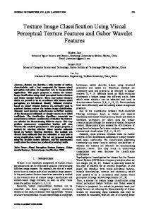
Blended Mipmap
The Proposed Method
16x Anisotropic Filtering
Figure 1: Our algorithm takes as input an ordinary texture with 8 bits per channel and converts it into a line integral texture with 32 bits per channel. The line integral texture allows us to achieve anisotropic filtering while using fewer samples than hardware. These images show a section of a typical game scene rendered using blended mipmapping, the line integral method, and 16x hardware anisotropic filtering. 1 2 3 4 5 6 7 8 9 10
Abstract In real time applications, textured rendering is one of the most important algorithms to enhance realism. In this work, we propose a line integral texture filtering algorithm that is a both fast and accurate method to improving filtered image quality. In particular, we present an efficient shader implementation of the algorithm that can be compared with 16x hardware anisotropic filtering. The authors show that the quality of the result is similar to 16x anisotropic filtering, but that the line integral method requires fewer samples to function, making it a more efficient rendering option.
11
I.3.7 [Texture Filtering]: Computer Graphics—Real-time Rendering
12
Keywords: texture, filter, anisotropic, real-time rendering
28 29
30 31 32 33 34 35
36 37 38 39 40
13 14 15 16 17 18 19 20
21 22 23 24 25 26 27
1
Introduction
Textures are a popular way to add detail to 3D scenes. However, because they are an approximation of actual geometry, they must be filtered to achieve satisfactory results. Traditional methods to filter textures include nearest neighbor, bilinear, bicubic, trilinear, and anisotropic filtering. These methods vary in reconstruction quality, particularly when the texture in question is being viewed at an extreme angle. Nearest neighbor filtering suffers extreme aliasing, especially at glancing angles or when minified. Bilinear filtering improves the situation by taking four samples, and modern graphics hardware optimizes it to be nearly as fast. However, when minifying, aliasing reemerges. Trilinear filtering effectively allows for the bilinear filter’s footprint to cover any size square area in texture space, resolving aliasing during minification. However, mipmaps suffer from
41 42
overblurring and/or undersampling when the texture is viewed at an angle, because the necessary sampling area is anisotropic. Traditional hardware anisotropic filtering algorithms improve on these techniques by taking multiple samples inside this anisotropic sampling region. Although this approach is simple to implement, the result is merely an approximation. Also, for good results, oftentimes many samples must be taken. For some angles, texture quality suffers unavoidably. The proposed line integral method addresses these issues. The line integral method computes a more accurate average sample inside the texture footprint, thus leading to more accurate visual results. The line integral method rivals the quality of even the best hardware anisotropic filtering but tends to require fewer texture samples than traditional anisotropic filtering, saving texture bandwidth and therefore rendering time.
47
The algorithm, implemented in a GLSL shader, already provides similar performance and quality to the algorithms of highly optimized current hardware. If the line integral method were also to be implemented in hardware, it would perform faster than classic anisotropic filtering, due to its greater efficiency.
48
2 Previous Work
43 44 45 46
49 50 51 52 53
54 55 56 57 58
59 60 61
1
Mipmapping: Mipmapping, also known in the context of twodimensional texturing as “trilinear filtering”, has been used since 1983 [Williams 1983]. Mipmapping works by sampling from a prefiltered texture image. By choosing an appropriate mipmap level, there will be less aliasing of high frequencies in the texture. Although mipmapping solves the aliasing problem inherent to texture minification, unfortunately, the prefiltered images are not directionally aware, and so when the minified texture is sampled anisotropically, the texture’s quality suffers either through overblurring or undersampling. Summed Area Tables: Another approach introduces the summed area table to compute areas inside a sampling region [Crow 1984]. The algorithm works by adding and subtracting rectangular sums.
Online Submission ID: 0180 62 63 64 65 66
The summed area table can easily compute a rectangular region, but cannot compute rectangles that are not aligned with the axis of the table nor arbitrary quadrilaterals. In addition, precision issues prevent the table from being practical for 32 bit textures, especially for large image sizes.
121 122
123 124
67 68 69 70 71 72
Anisotropic Filtering: Traditional hardware anisotropic filtering improves upon standard texture filtering, usually being used in conjunction with trilinear or standard bilinear filtering. Anisotropic filtering takes multiple samples from within the sampling area, allowing the hardware to average multiple samples together for a more accurate result [NVIDIA 2000].
125 126 127 128 129 130 131
73 74 75 76 77
Unfortunately, the algorithm is an approximation to an actual average sample, and thus a large number of samples must be taken for good quality. The proposed algorithm typically requires fewer samples than hardware anisotopic filtering, and is capable of producing better results.
132
133 134 135
78 79 80 81 82 83 84 85 86 87 88
89 90 91 92 93 94 95
96 97 98 99
Other: Some other, such as Texture Potential Mipmapping [Cant and Shrubsole 2000] and Fast Footprint Mipmapping [Huttner and Strasser 1999], are hybrids of summed area tables and mipmaps (and variations on these techniques). By combining prefiltering and summed area tables, these authors were better able to anisotropically sample textures. However, both summed area tables and mipmapping remain inherently limited to axis-aligned sampling rectangles. The best known of these approaches is the RIP-map structure, which prefilters images in each direction. This allows for sample footprint to run in the “U” or “V” texture directions, but still remains ultimately orthogonally confined.
136
Others have attempted to refine the basic technique of classic anisotropic filtering by weighting and choosing their samples carefully. Such techniques include “Feline” [McCormack et al. 1999], and the Elliptical Weighted Average [Greene and Heckbert 1986]. These can provide very compelling results, because they weight samples nearest the pixel center more strongly, thus more accurately approximating a sinc function.
147
Still others seek to invent new hardware to solve the anisotropic filtering problem. “Texram” [Schilling et al. 1996], [Shin et al. 2006], a dedicated chip for anisotropic filtering, did something very similar to present-day hardware anisotropic filtering.
137 138 139 140 141 142 143
144 145 146
148 149 150 151
152
153 154 155 156 157
100 101 102 103 104 105 106 107 108 109
110 111 112 113 114 115 116 117 118
3
Line Integral Texture Filtering
158 159
For practical purposes, the world can be thought of as an analog function–defined everywhere; everywhere continuous. When a digital picture is taken, the real world is quantized into a twodimensional collection of samples from this analog signal. Equivalently, when a texture is created from scratch, the imagined world is sampled in the same way–being reduced to a finite number of samples. Ideally, in the application, we would like to represent the original analog signal again. To do this, we must use a reconstruction filter to recreate an everywhere-defined continuous function.
160
A texture can be thought of as a two-dimensional grid of samples. The ideal reconstruction filter for a texture is the sinc function. Therefore, the ideal color of a texture sample can be found by weighting samples under a sinc function originating at that point. In practice, because the sinc function is infinitely complex, we use discrete approximations to it instead. The two most common are the nearest neighbor and bilinear reconstruction kernels. These are implementation standards, and are available on nearly every graphics platform.
169
161 162 163 164
165 166 167 168
170
171 172 173 174
175 176
119 120
However, there is a second sampling and reconstruction phase that is often overlooked: the now continuously defined reconstructed
177 178
2
texture is sampled again at each pixel it subtends, before being reconstructed on the screen as a pixel (itself a 2D rect function).
3.1 Motivation The one sample the pixel nominally takes in the second sampling step is often a poor representation of the now continuously defined texture. Even if that sample were representative of the texture at that location, the pixel’s color would only be accurate at that one location–other positions on the pixel would be inaccurate. Of course, a pixel can only display one color, so the ideal color is an average of all the possible samples under the pixel footprint (the quadrilateral a pixel’s outline subtends when projected into texture space). This is almost never the case for a single sample. 3.2 Algorithm The line integral method is based on the observation that these two sampling/reconstruction phases can be combined into a single operation. Traditional approaches first reconstruct the texture with a nearest neighbor or bilinear filter. Then, they sample that reconstructed texture at each pixel’s center, before finally reconstructing it on the screen with the pixel itself. The line integral method combines these operations into a single step, so that the texture reconstruction and the pixel reconstruction happen all at once, ensuring that the pixel’s final color is representative of the ideal colors inside a pixel footprint. The line integral method defines a new kind of texture–the line integral texture–constructed from an original, ordinary source image. An example of a texture, its line integral texture, and a depiction of the following algorithm may be found in Figure 2. Each texel in the line integral texture corresponds to the sum of all texels below it in the same column in the original source image. I.e., for a texture M by N pixels, and a sampling function f(m,n), then point P = m,n in the line integral texture has a value: ∫y S(x, y) = 0 f (P.x, P.y) dy Note that because standard byte textures may only hold 256 possible values per-channel, whereas a given sample could store the accumulated values of hundreds or a few thousand pixels, the line integral texture must be floating point. This gives the proposed method the same memory footprint as a summed area table. However, unlike classic summed area tables, in which precision becomes a problem due to integrating over a very large area, because we only integrate over a one dimensional region, the spread and error of values in the line integral texture is not extreme. In practice, single precision is far sufficient for the line integral texture. In addition, because the line integral texture only stores one-dimensional integrals, arbitrary sampling quadrilaterals may be computed. The algorithm continues by computing each pixel’s footprint in texture space. An edge-walking algorithm then steps across the pixel footprint, finding the total texel sum along each column by sampling from the line integral texture. A sum from a column may be found as the difference of two samples from the line integral texture. Once the samples are accumulated, the algorithm divides the final sum by the number of texels underneath the pixel footprint. The resultant color retrieved with the line integral method is then an accurate average color of the original texture under the pixel footprint.
3.3 Implementation Notes The line integral method is implemented in GLSL. By contrast, anisotropic filtering is implemented in hardware. This makes direct comparison of performance impossible.
Online Submission ID: 0180
A
B
C
Figure 2: Left: For a given point “A”, the line integral texture will store the sum of all the texels in the original image below “A” in the same column. Sums of any vertical line segment may be found by subtracting samples from one another (for example, the sum between points “B” and “C” is equal to the sample at “B” minus the sample at “C”). By using this technique, we can find the sum under any given sampling quadrilateral (grey). Center: A source image. Right: The line integral texture created from the source image, tonemapped to fit in the visual range.
179 180 181 182 183 184 185 186
187 188 189 190 191 192 193 194 195
196 197 198 199
To calculate the pixel footprint in texture space, we had to calculate the per-pixel derivative of the texture coordinate. However, the built-in GLSL functions “dFdx(...)” and “dFdy(...)” operate on four-fragment areas simultaneously. This causes four fragments to share the same derivative value. To correct this, we implemented a two-pass algorithm, wherein the texture coordinates are read out into a floating-point framebuffer in a prepass, being fed into the line integral algorithm. We find that this creates more accurate results. We found that hardware bilinear interpolation of floating point textures is done with 8-bit precision, yet the algorithm depends on taking accurate interpolated samples from a floating point texture. Sampling from areas close together in texture space would return the same texture value, leading to a sum of zero. In practice, this manifested itself as 256 black bands between individual texels, instead of a smooth gradient. We corrected this issue by taking four nearest neighbor samples and executing the bilinear interpolation manually in the shader. We present framerate benchmarks to demonstrate that even with all these handicaps, the line integral method still produces realtime framerates. However, we provide texture sample counts as a more realistic comparison of performance.
205
On our testing machines, there is no extra performance penalty for sampling from a 32 bit texture as opposed to an 8 bit texture. We tested this by sparsely sampling over a large texture, so as to avoid caching optimization. Thus, it makes sense to compare sample counts between 16x hardware filtering and the line integral method, because each sample takes the same amount of time to retrieve.
206
4
200 201 202 203 204
Figure 3: Quantitative tests. Left to right, ground truth, 16x hardware filtering, line integral method.
Figure 4: Source images used for qualitative tests
220 221 222 223 224 225
230
Unfortunately, no ground truth reference was available for the realtime engine, so no mean squared error results were computed– instead, we direct the reader to the accompanying video, which demonstrates the qualitatively the practical effectiveness of the line integral method.
231
4.2 Demonstration of Performance
226 227 228
207 208 209 210
Results
We began initial tests in a simple demo that renders a single planar surface using the line integral method. We then integrated the shader into code based off of the Quake 3 engine to demonstrate that the algorithm is robust and practical enough for realtime use.
229
232
211
233 212 213 214 215 216
ing that the algorithm functions as a solution to anisotropic texture reconstruction. Quantitatively, the algorithm’s quality exceeds that of hardware anisotropic filtering. We attribute most of the error in the line integral algorithm to our handling of polygon edges, which could be improved. However, even with these unnecessarily large errors, the line integral method regularly beats hardware filtering.
4.1 Comparison to Ground Truth In the controlled environment of the simple plane demo, we show how the algorithm’s accuracy compares with standard techniques and with a ground-truth rendering, established with a ray-tracer using 256 random samples per pixel (Mental Ray in Maya 2011).
To demonstrate the algorithm’s usefulness in real-time scenarios, we use two heuristics.
Method 16x Anisotropic : Line Integral :
Scene 1 27.133 20.664
MSE Scene 2 Scene 3 6.593 50.090 7.384 35.661
217
218 219
Table 1: MSE metric for measuring the error of the proposed algorithm versus hardware 16x filtering.
The MSE and MS-SSIM readings demonstrate that the line integral algorithm provides better quality than standard mipmapping, show-
3
Online Submission ID: 0180 Method 16x Anisotropic : Line Integral :
Scene 1 0.980 0.987
MS-SSIM Scene 2 Scene 3 0.975 0.515 0.982 0.676
Table 2: MS-SSIM metric for measuring the performance of the proposed algorithm versus hardware 16x filtering. Average frame rate Mipmap 267.7 fps 16x-Anisotropic 265.1 fps Line Integral 119.1 fps Table 3: Average framerates of the proposed algorithm in software versus traditional rendering algorithms in hardware
234 235 236
We begin by directly comparing the framerates of the application using different texture filtering modes. The results are summarized in the following table:
237
238 239 240 241 242 243 244
The results in the table clearly demonstrate that the line integral method is already easily fast enough for realtime use in an actual game engine. However, recall that, due to implementation specifics (see 3.3, Implementation Notes), the proposed method is disadvantaged in this comparison because it is not implemented in hardware and because it must take four times as many samples due to inaccurate hardware bilinear interpolation.
259
To provide a more adequate comparison, in our second heuristic, we compare the number of texture fetches each algorithm requires. Texture sampling is the largest bottleneck in almost any shader; by comparing the number of samples each algorithm requires, we gain a better measure of how the algorithms’ performance would compare if they were to be implemented similarly. We visualize the results in Figure 5. Green tinted samples represent areas where our algorithm uses fewer texture samples than does 16x anisotropic filtering, while red tinted samples represent areas where our algorithm uses more. Grey tinted pixels contain magnified texels, and so are irrelevant to both techniques. As the figure shows, our algorithm tends to use fewer samples than 16x anisotropic filtering. This result suggests that, because the line integral method requires fewer samples, it would outperform classic anisotropic texture filtering if they were both implemented in hardware.
260
4.3
245 246 247 248 249 250 251 252 253 254 255 256 257 258
261 262 263 264 265 266 267 268 269 270 271
Figure 5: Comparison of anisotropic texture filtering algorithms. Left to right: standard mimapping, 16x hardware anisotropic filtering, the proposed line integral method, texture sample count benchmark; green tinted pixels are areas where the line integral method requires fewer than 16 samples, and red tinted pixels where it requires more. Grey tinted pixels are magnified, and should not be considered.
278
288
289
Acknowledgements
280 281 282 283 284 285 286 287
Further Analysis
These quantitative quad demo MSE and MS-SSIM results demonstrate that, in controlled environments, the algorithm produces very good results comparable to 16x anisotropic filtering. The algorithm is robust and fast enough to function in a realtime game engine. In the game engine, the line integral method visually matches the quality provided by 16x anisotropic filtering–but, tellingly, the line integral method uses fewer texture fetches if the scene is considered as a whole (again, see 5). Therefore, in theory, if the line integrals method and the traditional anisotropic texture filtering method were implemented in a similar framework, the line integrals method would perform faster than the anisotropic texture filtering method.
291
The images used in this work were either generated by the authors or taken from the public domain.
292
References
290
293 294 295
296 272 273 274 275 276 277
5 Conclusion We have presented a novel algorithm for sampling and reconstructing textures that is both efficient and practical in real-time applications by the application of a new data-structure, the line integral texture. The line integral method frequently uses fewer samples per pixel than hardware anisotropic filtering, and can provide equivalent or superior image quality. The line integral method, implemented in a GLSL shader, already provides realtime performance despite a number of implementation difficulties. If implemented in hardware, its performance would exceed that of current, state-ofthe-art anisotropic filtering techniques.
279
The line integral method provides the greatest gain in efficiency when the sampling quadrilaterals are anisotropic in the same direction as the line integral texture. Future work would include the use of two line integral textures running at right angles to each other; the algorithm would then select the best approach given the characteristics of the pixel footprint.
297 298 299
300 301
4
C ANT, R. J., AND S HRUBSOLE , P. A. 2000. Texture potential mip mapping, a new high-quality texture antialiasing algorithm. ACM Trans. Graph. 19 (July), 164–184. C ROW, F. C. 1984. Summed-area tables for texture mapping. In Proceedings of the 11th annual conference on Computer graphics and interactive techniques, ACM, New York, NY, USA, SIGGRAPH ’84, 207–212. G REENE , N., AND H ECKBERT, P. S. 1986. Creating raster omnimax images from multiple perspective views using the elliptical
Online Submission ID: 0180 302 303
304 305 306 307
308 309 310 311 312 313
314 315 316
317 318 319
320 321 322 323
324 325 326
weighted average filter. IEEE Comput. Graph. Appl. 6 (June), 21–27. H UTTNER , T., AND S TRASSER , W. 1999. Fast footprint mipmapping. In Proceedings of the ACM SIGGRAPH/EUROGRAPHICS workshop on Graphics hardware, ACM, New York, NY, USA, HWWS ’99, 35–44. M C C ORMACK , J., P ERRY, R., FARKAS , K. I., AND J OUPPI , N. P. 1999. Feline: fast elliptical lines for anisotropic texture mapping. In Proceedings of the 26th annual conference on Computer graphics and interactive techniques, ACM Press/AddisonWesley Publishing Co., New York, NY, USA, SIGGRAPH ’99, 243–250. NVIDIA, 2000. Ext texture filter anisotropic. //www.opengl.org/registry/specs/EXT/ texture_filter_anisotropic.txt, apr.
http:
S CHILLING , A., K NITTEL , G., AND S TRASSER , W. 1996. Texram: A smart memory for texturing. IEEE Comput. Graph. Appl. 16 (May), 32–41. S HIN , H.-C., L EE , J.-A., AND K IM , L.-S. 2006. A cost-effective vlsi architecture for anisotropic texture filtering in limited memory bandwidth. IEEE Trans. Very Large Scale Integr. Syst. 14 (March), 254–267. W ILLIAMS , L. 1983. Pyramidal parametrics. In Proceedings of the 10th annual conference on Computer graphics and interactive techniques, ACM, New York, NY, USA, SIGGRAPH ’83, 1–11.
5