architecture for a collision avoidance system developed for a fleet of sensorless
mobile vehicles. The system has been deployed in the IT Convergence Lab in ...
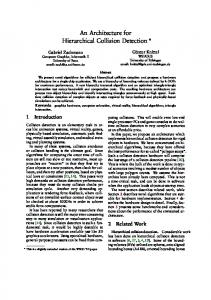
Architecture and Algorithm for a Laboratory Vehicle Collision Avoidance System C. L. Robinson, H.-J. Schutz, ¨ G. Baliga and P. R. Kumar Abstract— In this paper we describe the application architecture for a collision avoidance system developed for a fleet of sensorless mobile vehicles. The system has been deployed in the IT Convergence Lab in the Coordinated Science Laboratory at the University of Illinois at UrbanaChampaign, which is a testbed for studying system architecture for networked embedded control systems. We describe several factors that a well designed collision avoidance algorithm needs to address, and discuss some of the tradeoffs and design decisions that need to be made. The solution that we have developed has a minimal effect on existing components for higher level functionality, as well their interfaces. The architecture and algorithm provide a low level safety guarantee regardless of higher level objectives. The architecture exploits the infrastructure and services provided by the control domain middleware, called Etherware, which has been developed in the Laboratory. Indeed, the development of the collision avoidance system shows the usefulness of the specific services and abstractions that Etherware provides to the application designer in facilitating rapid system design and deployment.
I. I At the IT Convergence Lab in the Coordinated Science Laboratory at the University of Illinois we have been investigating system architecture issues involved in the convergence of communication, computation and control technologies [1], [2]. In this context we have developed a vehicular testbed (see Figure 1) as a representative distributed networked embedded control system. In this paper we investigate the problem of collision avoidance, which we have found to be important for this laboratory system. Despite explicit attempts to avoid collisions at higher architectural levels, a low level collision avoidance/safety guarantee for all system behaviours was deemed necessary. This represents a decoupling of the global goals of reaching a destination from the local priorities of collision avoidance. We employ an approach somewhat similar to the ideas presented in [3], [4] while focusing on system architecture, integration and development. This material is based upon work partially supported by NSF under Contract Nos. CCR-0325716 and CNS 05-19535, DARPA/AFOSR under Contract No. F49620-02-1-0325, DARPA under Contact Nos. N00014-0-1-1-0576, Oakridge-Battelle under Contract 239 DOE BATT 4000044522 and AFOSR under Contract No. F49620-02-1-0217 C. L. Robinson is with the Department of Industrial and Enterprise Systems Engineering and the Coordinated Science Laboratory, P. R. Kumar is with the Department of Electrical and Computer Engineering and the Coordinated Science Laboratory, University of Illinois at Urbana Champaign, H.-J. Schutz ¨ is at Muenchen University of Technology in Germany, and G. Baliga is with Google Inc.
After briefly giving some background into the collision avoidance problem in Section II, in Section III we introduce the I.T. Convergence Lab, as well as a networked control oriented middleware called Etherware [5], [6], which has been developed in the lab. Then in Section IV we discuss how collisions can still occur despite explicit design measures which were intended to avoid them. We also discuss some of the features an effective collision avoidance algorithm should possess. This leads us in Section V to a discussion of the concept of pre-clearance, and some of the considerations involved in implementing collision avoidance based on the pre-clearance idea. Section VI contains a description of two potential architectures for implementing the solution as well as a discussion on a third chosen architecture, and how Etherware services were used in the process. Finally, in Section VII we discuss some of the tests that were performed on the deployed system and some of the lessons that were learned. II. B R L Object avoidance, safety preservation and deadlock avoidance are common problems when dealing with multiple dynamic agents in both constrained and unconstrained environments, airborn, grounded or underwater vehicles, highway systems and many other problems [4], [7], [8], [9]. Although each case may be unique, the underlying problem is often how to manage the tradeoff between system safety and liveness. There are several potential solutions to this from both theoretical and practical standpoints. For example, independent agents each with a set of sensors and navigational devices represent one potential approach [10], [11], [12] under which the vehicles sense their environment and attempt to avoid any obstacles using methods such as potential fields [13], certainty grids [14], the curvature-velocity method [15] and others [16]. However, under this sensing scheme the only information available to an agent is localized, which makes achieving global goals difficult due to local minima. Alternatively, global information schemes generally have more success and reduce the problem to one of path planning [17], [18]. Recent advances in communication and computational capacity have given rise to the exciting possibility of enabling collaboration between vehicles in order to perform collision avoidance [19], [20]. However, even under this paradigm there are issues of priority,
scalability, robustness, implementation restrictions and dependency analysis that need to be considered. This paper considers some of these problems and presents a implemented solution appropriate for our laboratory. III. I IT C L A. Physical System Overview The IT Convergence Laboratory in the Cooordinated Science Lab at the University of Illinois, UrbanaChampaign was developed to provide a testbed for the development, deployment and evaluation of design patterns, software architecture and abstractions for networked and distributed control systems [1]. The laboratory consists of multiple remote controlled vehicles moving autonomously on a 4.5x3.5m track as shown in Figure 1. An example software schematic layout of a particular application is shown in Figure 2. The cars are monitored by two ceiling mounted cameras whose images are processed independently by two desktop computers called Vision Sensors, to yield vehicle position and orientation information. The vehicles do not have any on board sensors. A centralized or distributed Supervisor determines the high level objectives for each vehicle (e.g., drive to a particular location at a particular time). The trajectory which the vehicle is to follow is generated by a separate Trajectory Planner component which may also be distributed. A trajectory consists of a sequence of timed waypoints (i.e. a sequence of (x, y) coordinates and an associated time when the vehicle should be there). Depending on the application, the trajectory planner may choose non-intersecting trajectories, collision free trajectories or disregard collisions all together. The responsibility of computing the control action required to follow the trajectory is handled by a separate Controller component which is unique for each vehicle. Model predictive control is used to generate a sequence of control actions to be implemented over a future horizon of approximately 1.2 seconds. A different control action is implemented every 100ms and hence a buffer of up to 12 future control actions is created by the controller and sent to the actuator in a control buffer [21]. Each command has an associated implementation time and if delayed the current control command is implemented and older commands are ignored. The actuator sends the appropriate control action to a R.F. transmitter which delivers the control command to the vehicles. B. Control Domain Middleware: Etherware The underlying objective of the lab is to study the issues associated with designing and building control systems that operate over networks. Toward this end, each of the components in Figure 2 operate on machines separated by a network. Thus, system development is complicated by distributed systems and network issues including addressing, clock synchronization, lost communication packets, time delays, etc.
Fig. 1.
The IT Convergence Lab.
. Supervisor
Trajectory Planner
Controller
Controller
Controller Vision Sensor
Collision
Avoidance Vision Sensor
Actuator
Actuator
Actuator
Fig. 2. IT Convergence Lab Schematic. Boxes represent components, solid lines network interfaces, and dotted lines R.F. links.
In an effort to solve some of these issues from a control system perspective we have developed a middleware for networked control systems called Etherware [5], [6]. The objective of Etherware is to provide infrastructure and services to users so as to enable rapid, flexible and extensible deployment of their control applications. Examples include: 1) Semantic Addressing: Components are identified by a user specified profile. Other information (e.g. process ID, IP address) is hidden. Thus a user need only specify the profile of another component and message delivery and component interaction is managed entirely by Etherware, irrespective of where it is executing. 2) Filtering: Any message passed between two components can be filtered by a third entity which is able to ‘tap’ into the message stream. 3) Message Streams and Message Identification: Communication between components is conducted through message streams which were actively managed by Ether-
ware. They are addressed as first class identities called pipes which have a user defined profile. Thus, using the capability, as well as semantic addressing, a filter can be deployed on a communication pipe by specifying the profile of the messages it is to act on - irrespective of the message origin, message destination or filter location. If a connection is broken, components are informed of the failure. Connections are re-established when the components are restarted. In addition, quality of service (such as TCP or UDP) requirements can be associated with a particular stream. 4) Timing Services: Alarm clocks, periodic wake-up signals and delay measurement services enable enable the familiar interrupt-driven program design for control components. A Time Translation service is built into the middleware. The time value (‘time stamp’) associated with data sent between two nodes is transparently translated to the local time reference. This reduces some of the problems associated with network delays. 5) Component Management: Etherware manages all software in the system as a set of components and enables their interaction with the rest of the system. This protects other components from failure and enables component upgrade, restart and migration [5]. 6) Component Registry: Any component in the system is recorded in a Profile Registry. Any component can use the registry to identify and communicate with other components in the system that meet its specifications. This paper is an illustration of Etherware’s utility as the collision avoidance project was completed in less than 4 man months by a single developer with no prior knowledge of Etherware or network programming. IV. P D S R Under the existing architecture, trajectories are generated by the trajectory planner using knowledge of vehicle locations and destinations. Non-intersecting or collision free trajectories such as the traffic scheduling algorithm [22] currently deployed can be designed. However, several assumptions on system behaviour are required for reliable performance: 1: Control actions are recalculated at 20Hz. The trajectory planner re-plans at 0.5Hz. Thus, at times the control actions are based on a 2 second old trajectory which assumes good vehicle adherence. This highlights an implicit assumption that a scheduled trajectory matches the achievable one. 2: When reliable message delivery entails too much overhead, message delivery failure can cause some vehicles to receive an outdated trajectory or none at all. There is an assumption that updated trajectories are successfully delivered to controllers. 3: Misbehaviour by a vehicle (e.g. breakdown, low batteries, modeling inaccuracies) can cause a model mismatch. This assumption highlights modeling errors within a component, whereas the first item highlights modeling mismatches between components.
4: All trajectories are assumed to be executed simultaneously. Misbehaving vehicles have a cascading effect due to close timing requirements. A single delay at a stop street intersection could cause a large collision since vehicles do not account for others not exiting the intersection before executing their trajectory. The consequences of these assumptions are especially significant at higher velocities where small performance errors are magnified into larger safety issues. These considerations motivated a collision avoidance algorithm with the following characteristics: 1) Collision Detection: For purposes of reuse, upgrade and reconfiguration, it is desirable to separate this detection functionality from the avoidance mechanism. 2) Collision Avoidance: Once an imminent collision is detected an avoidance algorithm most satisfy physical and system constraints. It must also guarantee no future collision as a consequence of its actions. 3) Application Transparency: Policy changes at other levels in the system (e.g., traffic scheduling or pursuit– evasion) should not critically affect collision avoidance. Separating the detection and avoidance functionality from other system functionality provides a lower level system safety guarantee for all applications. 4) Minimal Performance Drawback: If performance must be compromised, the ability to tradeoff performance vs. safety for a particular application is desirable. Hence, the algorithm should be flexible enough to adapt to changing system requirements and topology. 5) Software failures: In addition to physical system failure (e.g., vehicle failure, hard drive error, or complete component failure), the algorithms should be robust to, and aware of, a variety of software logic failures. 6) Minimal System Modification: Many complex software components written by domain experts are required for the functionality of higher level applications. It is not desirable to make modifications to multiple (if any) of these components (and their interfaces) as it is complex and may make the system more brittle by introducing multiple new dependencies. 7) Use If Available: Collision avoidance should augment safe system behaviour as compared to being a critical dependency. V. C A A The basic functionality of the collision avoidance algorithm is discussed in this section. We first formally introduce the concept of pre-clearance and discuss some of the finer considerations that must be addressed in deploying an algorithm based on pre-clearance. We also discuss how Etherware and our chosen architecture meets the design objectives discussed in Section IV. A. Pre-Cleared Areas Consider the ith vehicle as an object of finite dimensions following a trajectory Ti in the space S; see Figure 3. A subset of S used to represent the vehicle is
called the Agent Area, Ai . Two vehicles are assumed to collide if their Agent Areas intersect. A pre-cleared area Pi is defined as a subset of S that is assigned exclusively to one agent (i.e. Pi ∩P j = φ for all i , j), and completely contains its Agent Area (i.e. Ai ⊂ Pi ). P2
A4
1
T2
4
A1
A2
A3
T1
2
P1
3
S
Fig. 3. Agent areas for vehicles 1 and 2 (A1 and A2 respectively) are completely contained within their pre-cleared areas P1 and P2 . Vehicles 3 and 4 collide since their Agent Areas intersect: A3 ∩A4 , φ.
B. Architectural Considerations If Ti ∈ Pi then the vehicle can proceed on Ti without consideration for any other agents, as it is the only object in Pi . This is the basis for our collision avoidance algorithm – assigning ‘safe’ pre-cleared areas for vehicles based on their intended trajectories. We have chosen a client-server type architecture in which a client, the Collision Avoidance Filter (CAF) requests pre-clearance areas from a Collision Avoidance Supervisor (CAS), as shown in Figure 7. This architecture will be elucidated further later in the paper. There are several complexities and considerations for using pre-clearance as a basis for collision avoidance: 1) How to determine the size of Pi ?: Assigning vehicles large areas would seem to be beneficial for liveness. This suggests a partition of the complete space among all the vehicles. However, updating the space is allocation for Pi , every P j adjacent to Pi must also be adjusted. Instead, the shape of the area should be based on vehicle capabilities and intended future trajectory but still tolerate modeling errors and minor modifications to the planned trajectory. This is a minimalist ‘assign no more area than is needed’ approach shown in Figures 3 and 4, and will be developed further later in the paper. 2) When to assign pre-cleared areas?: Assigning an area without knowledge and adherence by all vehicles could cause a collision. Any algorithm should register all agents before assigning areas. Vehicles should assume a safe mode of operation until given clearance. Finally, there should be a capability to deal with unregistered vehicles or obstacles. 3) What to do when a requested area is declined?: Since requested area are based on projected vehicle trajectories, an alternative trajectory would need to be devised. Instead of iterating between scheduling and collision avoidance algorithms to find an allowable trajectory, we define a default safety behaviour that must be approved at the end of any trajectory. In this
way if no further area is approved the vehicle can still operate in a safe manner. If a pre-cleared area contains a partial trajectory it must also contain the safety maneuver at the last approved trajectory point. The default safety behaviour for airplanes is a ‘loopy’ trajectory. For our vehicles it is stopping. Thus, any precleared area contains sufficient space to stop at the end of any approved trajectory. 4) How to reclaim pre-cleared areas?: Before an area is removed a guarantee is needed that the area is no longer required. This temporal knowledge can lead to an enhanced definition of a pre-cleared area that is space and time dependent. Areas are assigned for intervals of time. However, this critically depends on the vehicle performing correctly. A simpler and safer approach is to wait for a new pre-cleared area request before giving up an old area. This suggests assigning smaller areas (possibly requiring more frequent updates) in a client-server arrangement. This issue is also associated with failed components, vehicle removal and misidentification discussed in the following points. 5) How to deal with agent failure?: Agent should not leave pre-cleared areas under any failure condition. This is easier to ensure by assigning and removing precleared areas and enabling the default safety behaviour, as discussed above. 6) How to deal with delay?: Time taken for communication, message filtering, computing pre-cleared areas, etc. are all factors causing delay. In the case of large system delay (or packet loss) the default safety behaviour can be implemented. Having a local component (the CAF in our implementation; see Section VI) that can process information immediately can help reduce delay. Further, the migration service provided by Etherware [5] allows the system to dynamically position components and help manage delays. 7) Dealing with misidentified vehicles: Vehicles are occasionally misidentified as ‘ghost’ cars by the vision sensors. Future pre-cleared area requests may be declined due to the presence of the ‘ghost’ car. We address this classic false alarm – misdetection problem by a threshold on the number of times an object is observed before being accepted as an obstacle. The number is set based on testing and safety or liveness concerns. 8) How to deal with vehicles leaving the system?: When a vehicle does not leave the system correctly (components and message streams terminated, etc.) the pre-cleared areas should still be released. This is again a detection problem of ensuring that the vehicle has left the system. We assume that if a vehicle has not been observed for some time interval it has safely left the system. This can be modified if it causes safety problems by setting the time interval to infinity. 9) How to manage multiple system models?: To predict any future trajectory requires an accurate model. Correction factors and safety margins can be used to account for inaccuracies. To avoid modeling mismatches
between components that require some prediction / modeling capability, the same modeling component could be used by modifying its output to meet all component requirements. We have modified the model predictive controller to generate trajectories which are then appended to the control buffer command sequence sent to the actuator. The filtering capability (Section IIIB) taps this message stream and makes the trajectory available to any other system component. 10) How to prioritize requests for clearance?: Although a first come first serve approach is sufficient, the ability to prioritize some vehicles is useful for, say, approving emergency vehicles [23]. A local component that immediately approves simple area requests could allow some simultaneous processing.
Controller
Trajectory Planner
Collision Avoidance Filter Collision Avoidance Filter
Actuator
Collision Avoidance Supervisor
B A
Controller
Actuator
Fig. 6. Here the CAF is separated from the controller, which mitigates some of the disadvantages in Figure 5 and enabling simple start up, upgrade and removal. However, the controller logic must still be modified significantly to buffer control commands until approval is obtained from the CAF. This architecture divides and duplicates the collision avoidance logic since the controller waits for approval from the CAF, which in turn requests approval from the CAS). Finally, multiple interfaces will incur unnecessary delays. This architecture too was not deemed implemented.
P2
B. Implemented Architecture
A2
Pre-Cleared Approved Declined
2
T2
Fig. 4. Formation of bounding areas around a vehicle trajectory. If the area lies within the pre-cleared area the associated control actions are approved. Otherwise an increase in the area is requested.
The implemented architecture is shown in Figure 7. The modeling component in the controller is used to generate a trajectory. This reduces model mismatches between components. The trajectory information is added to the Control Message Stream (CMS) between the controller and actuator. The stream is filtered by the CAF component using the filtering, pipes and timing services provided by Etherware (Section III-B). We now discuss each of the components in this architecture.
VI. C A A A. Potential Architectures Several of the considerations above indicate a clientserver type solution. The system architecture we have adopted is divided into a client component called the Collision Avoidance Filter (CAF) that requests a pre-cleared areas, and a server component called the Collision Avoidance Supervisor (CAS) that assigns areas. We first consider two alternate architectures in Figures 5 and 6 and then discuss the implemented solution. Actuator
Collision Avoidance Supervisor Collision Avoidance Filter Controller
Fig. 7.
Collision Avoidance Filter
Obstacle Detection
Collision Avoidance Supervisor
Controller
Collision Avoidance Filter
CMS
Actuator
B A
CMS
Actuator
The architecture that was chosen for implementation.
C. Collision Avoidance Filter (CAF)
Controller Collision Avoidance Filter Trajectory Planner
Trajectory Planner
Controller
B A
Actuator
Fig. 5. The CAF is integrated into the controller module and has the advantage of a small number of components and network interfaces. However, the complexity of the algorithm is now embedded in the controller. Hence, any CAF upgrade, modification or failure, would have directly effect the controller. In addition, the controller has to be modified to include the collision avoidance functionality. Thus this architecture was not used.
Each point in the trajectory filtered from the CMS is associated with a control action. The CAF compares a sequence of Agent Areas along the trajectory to the precleared area previously granted by the CAS (as shown in Figure 4). If Ai ∈ Pi then the control actions are approved, returned to the CMS and forwarded to the actuator. Otherwise a new pre-cleared area is requested from the CAS and only the commands that keep the vehicle in the pre-cleared area are approved. D. Collision Avoidance Supervisor (CAS) The CAS receives requests from the CAF and assigns non-intersecting pre-cleared areas. This is a purely geometric polygon intersection problem. If the space is available, the request is approved. A subset of the
request may also be approved. The CAS utilizes Etherware services such as notification of component or message stream failure and reliable message delivery to ensure areas are correctly assigned and removed from malfunctioning components. The CAS also incorporates geometric constraints such as unidentified obstacles using the Obstacle Detection component. Time delays incurred by processing and message redirection is managed by the time translation service. Upon initialization, the CAS can find all vehicles using the repository service and not grant pre-clearance areas until all CAFs have registered. The rate of requests increases with traffic density and number of agents. To prevent processing delays, multiple CAS could be given responsibility for different geographical areas. This decentralized architecture requires procedures for vehicles moving between areas, but a single CAS failure does not necessarily cripple the entire system. VII. R A video describing the successful implementation is available at the Convergence Lab website [1]. Several test scenarios were developed to test the system and tune empirical parameters. The scenarios included component failure, various initialization sequences, component migration, congested driving, removing vehicles, randomly adding objects and vehicles, inducing delays and using different supervisors. The algorithm performed well, but we do acknowledge some issues: 1: Failure of the CAS means that no vehicles are able to move. This is a safety tradeoff as a simple modification could allow the CAF to approve control commands once it is informed of the CAS failure. This creates a ‘use if available’ relationship. 2: The pre-cleared area size and accurate prediction of vehicle trajectories is critical for good performance in dense driving conditions. 3: As the trajectory planner updates the trajectory, an emergent behaviour occurs that occasionally breaks a deadlock situation. However, a robust deadlock resolution algorithm is still required. 4: Occasional modeling mismatches cause ‘almost collisions’ where the physical vehicles do not collide, but their Agent Areas intersect. Hence, no future precleared areas can be granted. This causes a deadlock. This can be partially avoided by increasing the size of the pre-cleared areas and improving the system model. 6: Component software robustness issues were identified and middleware safe guards developed [24]. ‘Ghost cars’ were identified is a subject of future work. VIII. C We have presented an algorithm for collision avoidance of sensorless networked vehicles based on the idea of pre-clearance. The algorithm has many of the properties identified for an effective collision avoidance algorithm. Throughout the deployment we have made
extensive use of services provided by an in house control domain middleware called Etherware which enabled rapid system development and deployment. R [1] http:://decision.csl.uiuc.edu/∼testbed, “IT Convergence Lab, Coordinated Science Lab, Univ. of Illinois at Urbana-Champaign.” [2] S. Graham, Issues in the convergence of control with communication and computation. PhD thesis, Univ. of Illinois at UrbanaChampaign, 2004. [3] D. Fox, W. Burgard, and S. Thrun, “The dynamic window approach to collision avoidance,” in IEEE Robotics & Automation Magazine, vol. 4, 1997. [4] J. Wang and S. Premvati, “Distributed traffic regulation and control for multiple autonomous mobile robots operating in discrete space,” in Proc. of the IEEE Int. Conf. on Robotics and Automation, pp. 1619–1624, 1995. [5] G. Baliga, S. Graham, L. Sha, and P. R. Kumar, “Service continuity in networked control using etherware,” IEEE Distributed Systems Online, vol. 5, no. 9, 2004. [6] G. Baliga and P. R. Kumar, “A middleware for control over networks,” Proc. of the IEEE Conf. on Decision and Control., 2005. [7] J. B. de Sousa and F. L. Pereira, “Specification and design of coordinated motions for autonomous vehicles,” in Proc. of the IEEE Conf. on Decision and Control., 2002. [8] P. Varaiya, “Smart cars on smart roads,” IEEE Transactions on Automatic Control, vol. 38, no. 2, pp. 195–207, 1993. [9] F. E. Wang, D. Zeng, and L. Yang, “Smart cars on smart roads: An IEEE intelligent transportation systems society update,” IEEE Pervasive Computing, vol. 5, pp. 68–69, Oct.-Dec. 2006. [10] J. Borenstein and Y. Koren, “Real-time obstacle avoidance for fast mobile robots in cluttered environments,” in Proc. of the IEEE Int. Conf. on Robotics and Automation, pp. 572–577, 1990. [11] H. Hu and M. Brady, “A Bayesian approach to real-time obstacle avoidance for a mobile robot,” Autonomous Robots, vol. 1, 1994. [12] R. Aufrere, J. Gowdy, C. Mertz, C. Thorpe, C. Wang, and T. Yata, “Perception for collision avoidance and autonomous driving,” Mechatronics, vol. 13, pp. 1149–1161, December 2003. [13] Y. Koren and J. Borenstein, “Potential field methods and their inherent limitations for mobile robot navigation,” in Proc. of the IEEE Int. Conf. on Robotics and Automation, April 1991. [14] H. P. Moravec, “Sensor fusion in certainty grids for mobile robots,” AI Magazine, pp. 61–74, Summer 1988. [15] R. Simmons, “The curvature-velocity method for local obstacle avoidance,” in Proc. of the IEEE Int. Conf. on Robotics and Automation, 1996. [16] J. Latombe, Robotic Motion Planning. Kluwer Acad. Pub., 1991. [17] S. Oliver, M. Saptharishi, J. Dolan, A. Trebi-Ollennu, and P. Khosla, “Multi-robot path planning by predicting structure in a dynamic environment,” in Proceedings of the First IFAC Conf. on Mechatronic Systems, vol. II, pp. 593–598, September 2000. [18] L. E. Kavraki, P. Svestka, J. Latombe, and M. Overmars, “Probabilistic roadmaps for path planning in high dimensional configuration spaces,” Transactions on Robotics and Automation, vol. 12, no. 4, pp. 566–580, 1996. [19] http://www.transitweb.its.dot.gov/cicas/cicas current act.htm. [20] C. L. Robinson, L. Caminiti, D. Cavney, and K. Laberteaux, “Efficient coordination and transmission of data for vehicular safety applications,” in The Third ACM International Workshop on Vehicular Ad Hoc Networks (VANET), pp. 10–19, 2006. [21] C. L. Robinson, G. Baliga, and P. R. Kumar, “Design patterns for robust and evolvable networked control,” in 3rd Annual Conf. on Systems Engineering Research, (New Jersey), March 2005. [22] A. Giridhar and P. Kumar, “Scheduling automated traffic on a network of roads,” IEEE Transactions on Vehicular Technology, vol. 55, pp. 1467–1474, Sept 2006. [23] G. Baliga, S. Graham, C. A. Gunter, and P. R. Kumar, “Reducing risk by managing software related failures in networked control systems,” in Proc. of the IEEE Conf. on Decision and Control., Dec 2006. [24] T. Crenshaw, C. L. Robinson, H. Ding, P. R. Kumar, and L. Sha, “A pattern for adaptive behavior in safety-critical, real-time middleware,” in Proceedings of the 27th IEEE Real-Time Systems Symposium, Dec 2006.