Automatic Block Decomposition Using Fuzzy Logic Analysis 9th International Meshing Roundtable, New Orleans, Louisiana, USA. Oct 2-5, 2000 Reza Taghavi Simulation Works Saint Paul, MN. USA
[email protected]
Abstract A method is presented for the automatic block decomposition of complex multi-component closed volumes. Decompositions produced by this method remain unchanged when the geometry undergoes minor parametric changes. This feature is attractive in time-varying geometry or design optimization problems. Examples of the application of this method to all-hexahedral mesh generation are also presented.
Tetrahedral versus hexahedral meshes In most engineering applications, automatic tetrahedral (tet) meshing offers a perfectly viable solution. However, hexahedral (hex) meshing is still in demand due to a host of reasons that are not always technical in nature: 1. Certain applications do not accept tets or cannot properly and accurately use tets 2. There is sometime a lack of symmetry or downright lack of accuracy associated with tets 3. Tet meshes may require up to an order of magnitude more elements than equivalent hex meshes, especially for boundary layers or high aspect ratio parts. 4. All things being equal, in general, applications exact a higher quality from tets than hexes 5. Tet meshes are harder to view and repair. For instance, the vertices of a one millionnode tet mesh, scaled to an XGA screen, will hardly leave any pixels for the cursor, let alone node labels. Additional requirements of variable geometry applications Variable geometry applications such as CFD in combustion chambers and stirred tank reactors, metal forming applications and geometric design optimization may have additional mesh requirements. Indeed, most engineering applications are conducted with mesh densities that are sub-optimal, and it is desirable that during geometry change, mesh adaptation be achieved mostly through stretching (homeomorphic transformation) of the mesh
while maintaining element connectivity intact for as long as possible. In this fashion, we can keep the number of rezonings to a minimum, and minimize truncation errors. We will call this a robust mesh. In manual mesh generation, a smart choice of the initial block decomposition relies on a robust block decomposition that enables the user to maintain the same blocking throughout the geometry change, limiting rezoning to the addition or removal of a few element layers here and there. In Delauney, advancing front or “Lego-type” mesh generation methods, there is no guaranty that a small parametric change in the geometry will not initiate a complete reshuffling of the mesh connectivity, thereby masking the changes we are looking for. Mapped meshes are, on the other hand, more robust. Fuzzy logic block decomposition In the context of this presentation, fuzzy logic block decomposition means a systematic investigation and grading of a very large number of admissible block decomposition alternatives, and selection of the one with the highest grade. Takahashi et al [1][2] and Takizawa et al [3] have proposed a fuzzy logic approach to twodimensional geometry recognition, and have successfully applied it to complex mesh generation problems. Here, we approach the problem of block decomposition as the search for the coarsest possible all-hex mesh of a closed volume. We are also looking for a robust (as previously defined) mesh that remains unchanged should
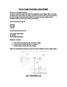
the geometry undergo “small” homeomorphic transformations. We will investigate a large number of coarse surface quad meshes, select those that are necessarily the surface mesh of a blockstructured volume mesh, grade each resulting volume mesh based on the quality of its elements, modify the surface quad mesh to achieve a better grade and so on. Automatic surface partition using fuzzy reasoning Step 1: Creating the coarsest block-structured mesh Consider an arbitrary closed triangular surface mesh S (Figure 1). Let’s assume that we already have a structured block decomposition of its internal volume. Vertices A, B, C, D, E, F, G and H represent the vertices of the block decomposition.
{Ai} is
the set of quadrilateral elements
constituting the outer surface of the block decomposition (here, Ai contains 6 quads, ADHE, BCGF, ABFE, DCGH, ABCD and EFGH). Each quad Ai is a collection of
{ }
neighboring triangles.
{Ai} with i = [1, n] , defines a partition of S : S = U Ai and ∀(i, j ) n
i =0
AIA i
As a result, we have ∑ Card ( n
i =0
j
=∅
ii.
iii. iv.
The partition contains at least 6 sets (a decomposition into one block requires n=6 quads) There is an even number of sets in the partition (juxtaposition of hexes always results in an even number of exposed (free) quads. Patch proximity rules are satisfied at every vertex of
{Ai}
…
Patch proximity rules result from the observation that in any block structured mesh, a vertex can only be surrounded by a certain number of hexes disposed in a precise way. Figure 2 shows the 8 possible configurations of a surface vertex in a block-structured mesh. For a given surface partition to be the outer surface of a structured block decomposition, it is necessary that the above rules be satisfied. 0 Starting with an initial partition , we check
{Ai}
for the above rules, and if any one is violated, we 0 1 perturb partition to obtain partition .
{Ai}
{Ai}
The perturbation of a partition is achieved by adding new quads to the partition or redistributing triangles among the various quads of an existing partition. Once we obtain a partition that complies with all the rules, we give it a grade based on the quality of the elements in the underlying block-structured volume mesh. If the grade is not satisfactory, we perturb the partition again and so on, using fuzzy logic reasoning, until all the rules are adhered to and last the grade is acceptable for . This surface
{Ai}
A )= N
partition represents the outer surface of the “solution” block decomposition.
i
Where: th • Ai is the i quad of the partition
To summarize:
• •
N is the total number of triangles S is the triangulated surface the interior of
•
which we want to decompose n is the total number of sets in the partition of S
Conversely, we argue that any partition
i.
{Ai} of
S is the outer quad mesh of a structured block decomposition of the interior of S , provided that it satisfies the following set of nonexhaustive rules:
1 2 3 4 5 6
starting with a surface partition if (all rules are satisfied) { build the underlying structured volume mesh and grade it if (grade target < grade) exit } create new partition redistributing triangles between sets go to 2
Once
{Ai}
last
is at hand, the internal elements
2.
Takahashi, H., Shimizu, H., Moriyama, H., Yamashita, Y. and Chiba, N., 1995, “A Three-Dimensional Mesh Generation System Using Shape Recognition Technique”, Transactions of the JSME, Vol. 59, No. 560, Series A (1995-4)
3.
Takizawa, C., Aoyama, H., Nishigaki, I., Yamashita, Y. and Chiba, N., 1996, “Automatic Hexahedral Mesh Generation System with Element Distortion Control Capability”, Transaction of the JSME, (1996-11)
and vertices of the mesh are obtained through a simple transfinite interpolation. Step 2: Block reduction This step consists in the identification of isolated corner hexes. The collapse of these elements results in the creation of an O-mesh (Figure 3). Application to all-hexahedral mesh generation Once the block decomposition is at hand, mesh generation simply consists in refining each block down to the user-requested level. Figure 4 shows three simple meshes obtained from the same block decomposition at three levels of resolution. Examples This methodology has been successfully implemented in the KUBRIX automatic mesh generator. Figure 5 shows several examples of engine components meshed using this method. Quality statistics Number of elements Max. elem aspect ratio % with aspect > 20 Min. vertex jacobian % with jacobian < 0.5 Max face warpage % with warpage > 45
A 1308 15 0 0.24 7 76 4
B 1522 16 0 0.17 6 145 6
C 5077 15 0 0.19 9 140 3
D 6880 120 1 .12 22 120 14
E 4205 61