CREATOR II works in the domain of software programming (as defined by Althoff et al. 1997). ... the programmer specifying the VHDL program through functional ...
Paulo Gomes and Carlos Bento, 1999. Automatic Conversion of VHDL Programs into Cases. In Proceedings of the International Conference on Case-Based Reasoning (ICCBR 99) Workshop: Practical Case-Based Reasoning Strategies for Building and Maintaining Corporate Memories. Germany.
Automatic Conversion of VHDL Programs into Cases1
Paulo Gomes and Carlos Bento Centro de Informática e Sistemas da Universidade de Coimbra Polo II – Pinhal de Marrocos, 3030 Coimbra, Portugal {pgomes|bento}@dei.uc.pt
Abstract Software programming is a complex task. To help the user with this task, we are developing a case-based reasoning tool capable of suggesting code to the programmer (software reuse). But, due to the dimension and complexity of software programs, acquisition of the case library is a hard task in this domain. In this paper, we show how a software program can be automatically converted into a case, which are described at a functional and behavioural level. The conversion rules presented here have been developed for procedural languages and enable conversion of basic language constructs into functional and behavioural knowledge. We also show some experimental results.
1
This work was partially funded by the Portuguese Ministery of Science and Technology under program PRAXIS XXI
Motivations and Goals Software programming is a hard design task, mainly due to the complexity involved in the process. Nowadays this complexity is increasing to levels in which reuse of previous software code is very useful to short cut the programming time. Case-Based Reasoning (CBR) (Kolodner 1993; Maher, Balachandran, and Zhang 1995) is a useful paradigm to develop tools for aiding software programmers in the coding phases. The working knowledge in case-based systems is its case library. Cases can be used to elaborate problems (Gomes and Bento 1997), solve old and new problems (Goel 1991), to do situation interpretation (Kolodner 1993), and other tasks. These cases are part of the corporate memory and can be reused by other company programmers, cutting down the coding phase of software development. Building a CBR system to do software design or just to help the software engineer in the task of code generation passes through a first hard phase. This phase is the creation of a case library. Software programs are big files describing what the computer system is supposed to do. But, they are not only big; they are also complex and require the knowledge engineer (the one responsible for the case library building) to know how each language instruction works. In order to overcome the case library construction phase we developed a method to do the automatic conversion of software files into case files. The goal of this method is to speed up the construction of the case library, by short cutting the case acquisition phase. We also developed a case representation for software design called Function-Behaviour Case Representation (FBCR). This paper focuses on the case acquisition method, which will be described in more detail. This method is applied in CREATOR II, a case-based reasoning system for digital circuit design using VHDL (VSIC Hardware Description Language). CREATOR II works in the domain of software programming (as defined by Althoff et al. 1997). CBR can be used in the software design domain at different levels. For example, Tautz and Althoff (1997) and Finnie et. al. (1997) use it at an organisational level, reusing the software knowledge used in the software development process. Others, like Fouqué and Matwin (1993) and Smyth and Keane (1995) have applied CBR to the software programming phase, like we do. The next chapter presents CREATOR II architecture. Then the FBCR formalism is presented, and then we will present the case conversion method and some experimental results.
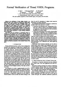
System Architecture CREATOR II is a Case-Based Reasoning system that helps the programmer developing VHDL code through the reuse of previous VHDL functions. The system’s architecture is presented in Figure 1. CREATOR II comprises four different modules: the VHDL to FBCR converter, the FBCR to VHDL converter, the Case-Based Reasoning module, and the Knowledge Base. In this paper we focus on the VHDL to FBCR converter and the process involved in the automatic case acquisition. The VHDL to FBCR converter converts a VHDL file into a FBCR case. In this process functional and behavioural knowledge is extracted from the VHDL code and used for indexing. The functional and behavioural knowledge is also used for case adaptation and verification. The Knowledge Base comprises four parts: the case library, the indexing structure, a function taxonomy, and a data taxonomy. The indexing structure is used for problem elaboration and case retrieval of cases in the case library. The function taxonomy is domain
knowledge used all over the system. It comprises a hierarchy of functions in the domain of digital circuit design. The data taxonomy is a hierarchy of data types used in the VHDL language and is also domain knowledge used by the system for reasoning tasks. VHDL to FBCR Converter VHDL Programs
FBCR to VHDL Converter
CREATOR II
Knowledge Base
Case-Based Reasoning Module
Programmer
Figure 1 - Architecture of CREATOR II .
The programmer interacts with the system through the CBR module. The system can help the programmer specifying the VHDL program through functional decomposition, retrieve VHDL functions for reuse, adapt VHDL functions to the new functional specifications, and present new solutions for VHDL program problems.
Case Representation The Function-Behavior Case Representation (FBCR) is used for representing software programs. This formalism is designed for description of procedural software languages, ranging from usual languages as C, to more specific languages, as VHDL. FBCR is derived from the Structure-Behavior-Function (SBF) models developed by Goel (1992). Because software programs can be seen as designs, FBCR describes a software program at functional and behaviour level. The functional level of the software program specifies the purpose of the design. The behaviour level describes how the design functions are achieved by the structure. In the remaining of this section, we describe how function and behaviour are represented in FBCR. Function The functional description of a design in FBCR is represented by a tree of functions. Each node of the tree represents a function, and each link represents a partonomic relation between functions. This allows a function to be decomposed into sub-functions, providing a functional decomposition view of the design. A function is described by an identifier name, input data, output data, behavior, subfunctions, class, and auxiliary data. Input, output and auxiliary data are sets of data objects. Data objects represent memory locations and are normally language variables, constants or parameters. Data objects are defined by an identifier, a data class (for example, the variable data type) and a set of properties. Properties are described by the property name, value and units. Input and output data objects are, respectively, input and output parameters of the function. Auxiliary data represent variables and constants, local to the function. Figure 2 presents the schemas for two functions: calculator and process. Input, output and auxiliary data contain pointers to data objects. The behavior field contains a pointer to the function behaviors. Each function has a class to which it belongs. A function taxonomy makes part of the system in order to do this categorization.
Function : calculator auxiliary data :input ; result behavior :calculator_behavior sub-functions :read_input ; process; visualize class : mathematic
Function : process input :input_data output :object1 auxiliary data : ... behavior : ... sub-functions : class : process_input
Figure 2 - The representation of functions calculator and process.
There are two levels of functions, corresponding to the ones that are leaves in the functional tree, and those that are not. In a higher level of abstraction, functions have a set of sub-functions, and may have a behavior graph. At the leaf level of the tree, functions do not have sub-functions, being described only by their behavior graph. A software design problem starts being described at an abstract level, down to the instruction level, and the functional description of the FBCR supports this type of representation. Functional description starts at the higher level of the functional tree, down to the behavior description. The process function in Figure 2 is at a level of abstraction bellow calculator. While the calculator function is a high level function. Behavior The behavior of a function is described by a graph comprising nodes and edges. Each node represents a behavior state, and an edge represents a transition between states. The behavior graph represents the data object transformations, from the initial state to the final state. In the process, data object properties can be changed, or data objects can be created or eliminated. An identifier and an initial state define a behavior graph. A behavior state represents the state of the data objects in a temporal instant of the system. A behavior state is defined by an identifier and by data objects. Behavior transitions represent the causes and constraints of the state transition. An identifier, a source state, a destination state, a set of causes and a set of constraints define each behavior transition. Causes comprise primitive functions or functions. Primitive functions represent the basic elements of the programming language being represented. There are two main types of constraints: data constraints and property constraints. In the next subsection, we describe constraints and primitive functions. Behavior Transition Labels Behavior transition labels can represent the constraints or the causes for a transition. In the first case, constraints are represented by boolean expressions that must evaluate to true in order for the transition to occur. There are two types of constraints in this category: data and property constraints. Data constraints are defined by a data object, a relational operator and a value, defining a Boolean expression. It states that the data object value must comply with the constraint defined by the relational operator and the value. The relational operator and the value are optional; in this case, the constraint means that the data object must exist. Property constraints are defined by a data object, a property, a relational operator and a value. This type of constraint represents a limitation that the data object property must comply with. In case the relational operator and value are omitted, the constraint implies the existence of the data object property. Constraints that cause the transition are named primitive functions. These constraints are low-level functions representing language instructions, operators or pre-defined functions. These constraints are specific to the software language in which the program is coded. The primitive functions play an important role in the FBCR formalism, connecting the behaviour level with the structural level. They make possible the conversion of behaviour graphs into software programs and vice-versa.
Converting Programs into Cases Procedural programming languages have a set of common constructs, which can be categorized in four main classes: declarations, statements, operators and sub-programs. These basic constructs have been the focus of our conversion method. Automatic case acquisition is done in the following steps: 1. Read VHDL file; 2. Perform a lexical analysis to the VHDL code; 3. Perform a syntax analysis of the tokens identified in step 2; 4. Perform a semantic analysis to the FBCR functions, data objects and data classes created in step 3. 5. Save the FBCR functions, data objects and data classes. The second step consists in the identification of the language tokens, such as literals, strings, numbers, and so on. In the third step the main language constructs are identified and converted into functions (with or without behaviour graphs), data objects, and data classes. In the next four sub-sections, we describe in more detail the conversion of each language construct. The third and final step comprises a coherence and consistency check of the functions, data objects, data classes and behavior graphs. The last sub-section of this section describes this process. Declarations Declarations describe data or process structure characteristics. We consider four main kinds of declarations: variable, constant, function, and type declarations. Variable and constant declarations are converted into data objects. Declarations have an associated data type, which is converted into the data object’s class. If there is an initialization value for the variable or constant, that value is transformed into the ’value’ property of that object. Function or procedure declarations are converted into functions. Its parameters and return value (in case of a function) are converted into input and output data objects. This is the only knowledge that can be extracted from the function declaration, though much more can be extracted from the function’s definition. Type declarations are converted into data classes. The data classes are then associated with the data types and form a taxonomy of data classes, providing domain knowledge. An issue important regarding data classes is to insert the basic data classes corresponding to basic data types (like integer for instance) in the taxonomy by the knowledge engineer. Statements Behavior knowledge is mainly encoded in the language statements and the instruction sequence. Because each procedural language has its own instructions, we identified the main categories of statements, and we will describe how each category can be translated into the FBCR. The statements presented here are converted into a behavior graph, which will be connected to other graphs, accordingly to the sequence of statements. (a) Simple assignment situation : A = B State 1 data : A ; B
Transition 1 primitive_function(=)
State 2 data : A (value : B)
(b) Expression assignment situation : A = B + C State 1 data : B ; C
Transition 1 primitive_function(+)
State 3 data : A (value : B+C)
Figure 3 - Conversion of assignment statements.
State 2 data : A ; obj1 (value : B+C)
Transition 2 primitive_function(=)
The first category comprises assignment statements. These instructions assign a value to a variable. The value can be another variable, an expression, or a procedural call. Assignments in the format ’A=B’, are converted into a behavior graph with two behavior states and one transition connecting them (see Figure 3a). Data objects involved in the statement are referenced in the first state. The resulting state has the data object whose value has been modified, with the correct value. Figure 3b shows a more complex situation, where the assignment is an expression. Each operator in the expression origins a new state and transition, linked has seen in the Figure 3b. Operator translation is described in the next subsection. Test statements are the second construct category. There are two main test instructions: ’if’ and ’case’. In the first one, a test condition originates a bifurcation in the program behavior. While in the ’case’ situation there are as many alternative paths as options in the statement. Figure 4a shows an example of a ’if’ statement conversion. In this example, the behavior graph is divided in two paths, one leading to the ’then’ branch and other to the ’else’ branch. In the ’then’ transition, the test condition is added as a constraint, while the negation of this constraint is added to the ’else’ transition. Figure 4b shows a ’case’ example, in this situation each transition has a constraint associated to the option branch. Final states are then linked to the behavior graph statements of the respective branch. (a) IF statement : (b) CASE statement :
IF (A=B) THEN statements1 ELSE statements2 State 1 data :
Transition 1 State 2 primitive_function(if) Statements 1 data : A=B Transition 2 primitive_function(if) A/=B State 3 Statements 2 data :
CASE (A) op1: statements 1 ... opn : statements n
State 1 data :
Transition 1 Transition n primitive_function(case) primitive_function(case) A=op1 A=opn
State 2 data :
...
Statements 1
State n data : Statements n
Figure 4 - Conversion of test statements.
Loop statements compose another category of procedural language constructs. There are three main types of loops: ’for’, ’while’, and ’until’. Loops generate a cycle in the behavior graph, with a normal exit transition corresponding to the test condition. This test condition originates two transitions, one that goes to the beginning of the statement loop, or one that goes to the next statement after the loop. The difference between the three loop types is in the position of the test condition and in the ’for’ case additional states and transitions needed to deal with the counter variable. In Figure 5 we show the conversion of a ’for’ statement. Notice the initialization of the variable i in states one and two. Then in state 3 there is a check to see if the test variable (i) has run out of range. If it has, the behavior graph will link to the next statement after the ’for’ statement. Otherwise, the behavior graph will continue in the next behavior state of the statements inside the loop. The transition from state four to five increments the test variable. This is the most complex loop of the three types considered. FOR statement : State 1 data : i
FOR i = n TO m DO statements
Transition 1 primitive_function(=) primitive_function(for)
State 2 data : i (value : n)
State 5 data : i (value : i + 1)
Transition 2 primitive_function(for)
State 3 data :
Transition 5 primitive_function(for) Transition 4 primitive_function(=) primitive_function(for)
State 4 data : i
Transition 7 primitive_function(for) i>m Transition 6 primitive_function(for) i