tions to the DCT-domain and processing a motion JPEG stream ... cheap and the video processing have to be embedded ...... Robust image registration by.
Bayesian Formulation of Image Patch Matching Using Cross-correlation Håkan Ardö and Kalle Åström Centre for Mathematical Sciences Lund University
Abstract—A classical solution for matching two image patches is to use the cross-correlation coefficient. This works well if there is a lot of structure within the patches, but not so well if the patches are close to uniform. This means that some patches are matched with more confidence than others. By estimating this uncertainty more weight can be put on the confident matches than those that are more uncertain. In this paper we present a system that can learn the distribution of the correlation coefficient from a video sequence of an empty scene. No manual annotation of the video is needed. Two distributions functions are learned for two different cases: i) the correlation between an estimated background image and the current frame showing that background and ii) the correlation between an estimated background image and an unrelated patch. Using these two distributions the patch matching problem is formulated as a binary classification problem and the probability of two patches matching is derived. The model depends on the signal to noise ratio. The noise level is reasonably invariant over time, while the signal level, represented by the amount of structure in the patch or it’s spatial variance, has to be measured for every frame. A common application where this is useful is feature point matching between different images. Another application is background/foreground segmentation. In this paper it is shown how the theory can be used to implement a very fast background/foreground segmentation by transforming the calculations to the DCT-domain and processing a motion JPEG stream without uncompressing it. This allows the algorithm to be embedded on a 150MHz ARM based network camera. It is also suggested to use recursive quantile estimation to estimate the background model. This gives very accurate background models even if there is a lot of foreground present during the initialisation of the model.
patches has enough structure. The contribution of this work is a probabilistic formulation that can assess how certain a correlation based match between two patches are and thereby allow the following steps to put more weight on more certain matches. The theory presented in this paper can be used for any algorithm that needs patch matching of patches of any size, such as stereo matching or feature point tracking. But the application considered here is background foreground segmentation in a large scale automated traffic surveillance application. With large scale we mean to cover the road network of an entire city section with cameras and generate trajectories for all road users such as cars, pedestrians and bicycles. There have been a lot of background foreground segmentations suggested, but non really suitable for this kind of application because •
•
I. I NTRODUCTION The correlation between two signals (cross correlation) is a standard tool for assessing the degree to which two signals are similar. It is a basic approach to match two image patches, for feature detection [4] as well as a component of more advanced techniques [3]. The technique has several advantages. Firstly, the cross correlation is fairly easy to compute. When used for matching a patch in a general position in an image, Fourier methods can be used to compute the cross correlation fast. Secondly, the cross correlation is independent of translations and scaling in the intensity domain. Thus it is fairly independent of lighting variations. Numerous authors use cross-correlation for matching, [3], [14]. However, there has been little attention to probabilistic models of the correlation coefficient. The technique has been shown to give good results in many situations where the
•
To handle this amount of cameras, they have to be fairly cheap and the video processing have to be embedded within the cameras. It is not plausible to transfer the amount of video data produced to a PC cluster doing the processing. The aim is to use cameras like Axis 207, which contains a 150Mhz ARM processor. This means that the algorithm have to be very computationally efficient. The proposed algorithm is for example about 100 times faster than [10] that can handle continuously varying backgrounds. The background typically consists of static pavement, which means that there is no need for such complex backgrounds. Neither is there a need for multimodal background models to handle swaying trees or rippling water, such as the mixtures of Gaussian suggested by Stauffer and Grimson [13]. The scene is outdoor, which means that the lighting conditions will vary. Not only due to the sharp shadows cast by the road users and the slow variations due to the motion of the sun, but also due to more diffuse shadows cast by passing clouds. Such passing clouds can move faster than the road users and has no distinct borders but will make the lighting vary smoothly over the image.
Friedman and Russel [5] have suggested to use a 3 component mixture of Gaussian where the three components represent pavement, pavement in shadow and foreground. This will work nicely on a sunny day when shadows consist of sharp shadows cast by road users. But on a cloudy day the diffuse clouds will generate a lighting of the scene that varies smoothly both
spatially and temporary, there will no longer be two distinct components but a continuous variation. A different approach is to preprocess the input image to extract intensity independent features and base the background model on those instead. However, many intensity independent features break down in dark or uniform areas. Take for example the normalised rgb, that transforms the colour pixel � � g b r (r, g, b) into r+g+b , r+g+b , r+g+b . When r, g and b all are small, the denominator becomes close to zero and the noise is scaled up out of proportion. Gordon et al [6] has suggested to ignore normalised rgb features in dark areas and there rely on other features instead. In their case the results from a stereo matching algorithm. A fix threshold was used to decide if the features were reliable or not. In the same fashion Hu et al [7] used 3 different models for background patches with different amount of structures. Also, Wayne and Schoonees [16] suggests to use two thresholds on the background likelihood to classify pixel into background, foreground and unknown depending on how close to the background model the current frame is. The unknown pixels are then filled in by a morphological post processing step based on their neighbours. This property of features being unreliable in some cases and very reliable in other cases is not a discrete property. It is a property that varies continuously from a patch with a lot of structure to a uniform patch or from a very dark pixel to a very light pixel. Features can be utilised much more efficiently by instead of thresholding them into reliable and not reliable, using a continuous estimate of how reliable they are and weight the different features accordingly. We suggest to divide the image into patches and to use normalised cross correlation to match such patches to a background model. Such comparison is independent both to translations and scaling of the intensity domain, which makes it fairly lighting independent. At least as long as the lighting is the same over the entire patch. This is typically the case for cloud shadows as they are diffuse and for the interior of sharp shadows. However at the borders of sharp shadows that is not the case, but foreground detections made at the very border of shadows can be removed by later processing steps that does not look at each block separately, but considers neighbours as well. A Markov random field for example[9]. Theoretical background and foreground distributions of the cross correlation coefficient is derived in [1] and the background distribution depends on a single parameter, the signal to noise ratio. The signal here refers to the amount of structure in the patch. Using Bayes rule and the likelihood produced by those distributions, the probability of each block showing background or foreground can be calculated. This makes it possible to use the cross correlation feature for all patches even if the amount of structure is low. In that case the foreground probability will be close to 0.5 and represent an uncertain state. The segmentation will then rely more on other features or on neighbours. This means that there will be no need to chose between several different distinct models. Instead the signal
snr=1
2
10
0
0
10
10
−2
−2
10
10
−4
−4
10
10
−6
−6
10
10
−8
−8
10
10
−10
10
snr=5
2
10
−1
−10
−0.5
0
0.5
1
10
−1
−0.5
0
0.5
1
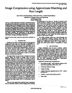
Fig. 1. Logarithmic plots of simulated distribution functions (crosses) for different signal to noise ratio, σ ˆ , together with the theoretical functions (solid lines). ffg is red and fbg is blue. d = 16.
to noise ratio is measured and a single parametrised model will move continuously from being very certain about highly structured patches to being very unsure about uniform patches. In [8] image patches are matched by first transforming the signal to a binary signal and then forming a correlation coefficient called increment sign correlation. They also calculate the distribution function of the increment sign correlation assuming a Gaussian noise model in image intensity. Much information is, however, lost in the binarisation and the remaining theory is only applicable for binary signals. The assumption made in [1] was that the foreground distribution arises from the cross-correlation between two random Gaussian distributed independent patches, and that the background distribution arises from the cross-correlation coefficient between two patches that differ only by scale, translation and additive Gaussian noise. This is an over-simplification. At least in the foreground case, where the probability of two unrelated patches, chosen from natural images, being correlated is fairly high. The theory does however give the conclusion that the main parameter that controls the shape of the distribution is the signal to noise ratio or the amount of structure in the patch. In this paper the foreground and background distributions will instead be learned from training data as a function of the measured signal to noise ratio. II. C ORRELATION C OEFFICIENT Here, the cross correlation between small patches, typically 4 × 4 or 8 × 8 pixels, will be studied. It is not dependent on the two dimensional structure of the patch, which allows each patch, a, to be represented as a one dimensional vector, a = (a1 , a2 , · · · ad ), where ak is the grey level of pixel k, and d is the total number of pixels in the patch. The order of the pixels is not important as long as the same order P is always ¯ = d1 ak , the used. The following notation for the mean, a ¯ and the length (amount of structure displacement, a ˆk = ak −P a 2 or variance), |ˆ a| = a ˆ2k will be used. The correlation coefficient, c, between two patches, a and b is defined as P ˆ ˆ ˆ a b a ˆ k bk = · , (1) c= ˆ |ˆ a | b ˆ |ˆ a| b where · denotes scalar multiplication. Note that c = cos α, ˆ ˆ and b. with α the angle between the two vectors a
ffg (c) = √
Γ πΓ
d 2 � d 1 2 − 2
�
1 − c2
� d−3 2
(2)
and √ fbg (c|ˆ σ) = ·
d−2 � X k=0
�
d−2 Γ k Γ
1 − c2 √ π � k+1 � 2 � d−2 2
d−4
e
c2 −1 2ˆ σ2
·
” “ c2 cΓ k+1 2 , 2ˆ σ2 c �d−2−k 1 + |c| − |c|Γ k+1 c ( 2 ) “ ” √ c2 Γ k+1 2 , 2ˆ 2ˆ σ σ2 Γ( k+1 2 )
k even .
1 % foreground
250
250
200
200
150
150
Intensity
Intensity
0 % foreground
100
100
50
0
50
0
1
2 Frame
3
0
4
0
1
4
x 10
10 % foreground 250
200
200
150
150
100
3
4 4
x 10
100
50
0
2 Frame
30 % foreground
250
Intensity
Intensity
The patch matching problem can be formulated as a binary Bayesian classification problem, with one feature, c. In other words, given a known patch and one or several candidate patches it is possible to calculate the probability, for each of the candidate patches, that they are noisy, rescaled and translated versions of the known patch using Bayes’ formula. To do that the distribution function, fbg (c), of correlating the known patch with a noisy rescaled and translated version of itself is compared with the distributing function, ffg (c), of correlating the known patch with a random uncorrelated patch. Distributions for these two cases are provided by [1]. The foreground distribution, ffg (c), will only depend on the dimension d, while the background distribution, fbg (c |ˆ σ ), will also depend on the signal to noise ratio l = σ1ˆ which is defined as the standard deviation of the noise, σ, divided by the amount ˆ i.e σ of structure (length) of the observed patch, |a|, ˆ = σˆ . |a| The distributions are
50
0
1
2 Frame
3
4
0
0
4
x 10
1
2 Frame
3
4 4
x 10
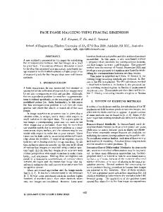
Fig. 2. Simulated intensity of a single pixel (grey). The pixel shows a background that is 80 in first half and 170 the second half mixed with different amount of foreground that is uniformly distributed between 0 and 255. The pixel is assumed to be measured with Gaussian noise with a standard deviation of 4 in the first half and 6 in the second. It’s mean (thick blue) and standard deviation (dashed blue) estimates using a learning factor α = 0.9993. It’s mean (thick red) and standard deviation (dashed red) estimates using a recursive quantile estimator with ct = 0.02.
(3)
k odd
Plots of a few cases are given i Figure 1. III. BACKGROUND MODEL To use the correlation coefficient for background/foreground segmentation a background model have to be constructed and updated continuously. It will not be assumed that this model is available apriorie nor that it is possible to observ the scene when it is empty, i.e. contains no foreground. Instead the background model will be estimated continiouls online while the system is running and foreground objects are present. This means that no manual initialisation is needed. Once the camera is mounted and the system started it will start estimate the background. During the first few minutes, output will not be reliable, but as soon as the model estimate has converged the output becomes useable. As mentioned above the typical backgrounds in the considered applications are unimodal and it is more important to lower the computational demands than handle multimodal backgrounds. The lighting does however vary and the background model need to be estimated and updated during such variations as well as with foreground objects present. The input image It at time t is divided into patches pj,t ˆ j,t p which are each normalised into |ˆpj,t | and a background path, bj , is estimated as the temporal median over those normalised patches. To estimate the noise level this background estimate is rescaled to the same length (the same lighting conditions)
as the observed patch and the difference |ˆ p | j,t bˆj − pˆj,t ˆ bj
(4)
will be used as an sample from the noise distribution. A. Recursive Quantile Estimation To get good estimates of the background image and the noise level even when there is a lot of foreground, recursive quantile estimation will be used. The mixture of Gaussian approach [5], [13], that only update the mean if the current pixel value is within 2.5 standard deviations of the mean can handle a lot of foreground. However it is a local optimisation algorithm, which might fail if there is no decent estimate of the mean to begin with. There is no guarantee that this approach will converge if it is initiated randomly, as is shown by a counterexample in the simulations below where it converges to something completely wrong, see Figure 3 lower right. The solution we suggest is to use the median instead of the mean and to estimate the variance from the 25/75% quantile. Möller et al shows [11] how to estimates quantiles recursively, and proves that it will converge under very general assumptions on the input data. They use a control sequence ct = max(c0 /t, cmin ), where constant c0 is a starting value that is typically chosen a few times larger than the maximum intensity value. After some time the sequence will become constant with value cmin . A larger value of this parameter will make the algorithm adapt faster to changes in the background.
1 % foreground 0.07
0.06
0.06
0.05
0.05 Frequency
Frequency
0 % foreground 0.07
0.04 0.03
0.03 0.02
0.01
0.01
0
50
100
150 Intensity
200
0
250
0
50
0.06
0.06
0.05
0.05
0.03
0.01
0.01
0
0
100
150 Intensity
100
150 Intensity
200
250
150
150
100
100
50
50
0
0
1
200
250
2
3
4
0
0
1
2
3
4
4 4
x 10
x 10
10 % foreground
0.03 0.02
50
200
30 % foreground
250
250
200
200
150
150
100
100
50
50
0.04
0.02
0
200
30 % foreground 0.07
Frequency
Frequency
10 % foreground 0.07
0.04
1 % foreground 250
0.04
0.02
0
0 % foreground 250
0
50
100
150 Intensity
200
250
0
1
2
3
4 4
x 10
Fig. 3. Normalised histogram over the the second half of the simulated pixel values from Figure 2 (grey) and the background estimations made by the three different algorithms: leaning factor (blue), recursive quantile (red) and Stauffer/Grimson (green).
The median B0.50,t (x), 25% quantile B0.25,t (x) and 75% quantile B0.75,t (x) of each pixel It (x) in a image sequence is found with if Bγ,t−1 < It Bγ,t−1 + γct Bγ,t−1 − (1 − γ) ct if Bγ,t−1 > It . Bγ,t = (5) Bγ,t−1 if Bγ,t−1 = It From these quantiles the variance, Vt , can be estimated using p B0.75,t − B0.25,t , (6) Vt = −1 −1 Ncdf (0.75) − Ncdf (0.25) −1 where Ncdf (x) is the inverse of the normal cumulative distribution function Z x Ncdf (x) = N (t |0, 1 ) dt, (7) −∞ −1 −1 Ncdf (0.75) − Ncdf (0.25) ≈ 1.349.
0
(8)
In the considered algorithm this will be applied to estimate ˆ p a background image as the median of |ˆpj,t , and a noise j,t | level as the standard deviation (6) of the noise samples from Equation 4. B. Simulations Figure 2 shows a plot of the simulated intensity of a single pixel in grey. In the top left plot the pixel always shows the background which is measured with additive Gaussian noise. The blue thick line shows the estimated background model using a learning factor to estimate the mean and variance and the two dashed blue lines shows an offset of two times the estimated standard deviation from this mean. The red lines shows the corresponding values but based on the 25%, 50%
0
0
1
2
3
4 4
x 10
Fig. 4. The simulated pixel as in Figure 2. Here the background distribution is estimated using the mixture of Gaussians algorithm by Stauffer and Grimson [13].
and 75% quantile estimations instead. Both estimates agree equally well with the ground truth after they have converged when there is no foreground. The learning factor and the step size have been chosen to make the convergence time of the two estimates approximately equal. In the top right image of Figure 2 the pixel is assumed to show the foreground 1% of the time. The foreground is modelled as uniformly distributed between 0 and 255. The quantile based estimator still gives the same result while the mean based overestimates the variance. In the bottom row the amount of foreground is increased even further and now the learning factor based estimator overestimates the variance even further and also overestimates the mean value when it is lower than 127 and underestimate it when it is larger than 127. The quantile based estimator still gives reasonable results. The mean of the last estimates archived right before the background intensity was changed and at the end of the sequence are shown in Table I. Also, normalised histograms of the data together with plots of the probability distribution functions estimated are shown in Figure 3. When using mixtures of Gaussians based algorithms [13], [5], the difference between using a learning factor as they do and the quantile estimates are not as striking. Figure 4 shows how the Stauffer/Grimson [13] performs on the same input data as in Figure 2. And the estimated background distribution is shown as a green line in Figure 3. A three component mixture, as suggested in [13], have been used. To make a fair comparisson with the other algroithms, the last step of that algorithm that tries to estimate how many mixture components there are in the background model have been hardcoded to always return the correct value one. This is becuase the simulated data is unimodal and the other algroithms assumes
GT 80 80 80 80 170 170 170 170
Mean LF 80.01 80.34 84.75 93.86 170.08 169.47 165.14 157.91
Value RQ 79.99 79.88 80.24 80.69 170.10 169.85 169.56 168.89
SG 80.02 79.91 80.00 79.97 170.10 169.89 169.98 29.85
GT 4 4 4 4 6 6 6 6
Standard LF 4.03 9.48 27.30 45.04 6.08 10.75 28.00 44.00
Deviation RQ SG 3.99 3.71 3.98 3.69 4.55 3.81 6.54 3.93 6.00 5.60 6.02 5.61 6.74 5.64 9.43 17.41
40 0.8
30
TABLE I R ESULTS OF ESTIMATING THE MEAN AND VARIANCE OF A G AUSSIAN BACKGROUND DISTRIBUTION MIXED WITH DIFFERENCE AMOUNTS OF UNIFORMLY DISTRIBUTED FOREGROUND . T HREE DIFFERENT METHODS : LEARNING FACTOR (LF), RECURSIVE QUANTILE (RQ) AND S TAUFFER /G RIMSON (SG) ARE COMPARED WITH THE GROUND TRUTH
SNR
Amount foreground 0% 1% 10% 30% 0% 1% 10% 30%
0.6 20 0.4 10
0.2
(GT).
0 −1
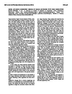
it to be unimodal. The algorithm performs very well in most cases. The variance is somewhat underestimated, but it should be possible to compensate for that by figuring out how much the estimate is biased. What’s troubling though is that when there is a lot of foreground present this algorithm might lock on to something completely wrong and then stick to that as has happened in the lower right plot of Figure 3 and Figure 4. This is because it is based on the EM-algorithm, which is a local optimisation algorithm that can get stuck in a local maxima. The convergence properties of the recursive quantile estimator are investigated in [11] and it is shown to converge under some very general assumptions on the input sequence. The result is also tabulated in Table I. IV. E MPIRICAL D ISTRIBUTIONS The assumptions presented in Section II are, at least in the foreground case, an over-simplification. But the theory still implies that the most important parameter that governs the shape of the distribution is the signal to noise ratio, l. By using a background model generated as described above and a camera looking at a scene with no moving objects an empirical background distribution, fbg (c |l ), can be learned by building a two dimensional histogram over the observed correlation coefficients and the observed signal to noise ratios. By reordering the blocks in the background image but not in the input frame, a foreground distribution, ffg (c |l ), can be estimated in the same way. The probability of foreground can then be found by assuming equal priors and using Bayes formula, p (foreground| c, l ) =
ffg (c |l ) . ffg (c |l ) + fbg (c |l )
(9)
The resulting distribution from the training is shown in Figure 5. All bins of the histograms were initiated with a single sample. That results in making events that never occurred in neither in the foreground nor the background during the training generate a foreground probability of 0.5 instead of being undefined. V. I MPLEMENTATION The presented approach is very well suited for processing motion JPEG compressed video. That is a video compression
−0.5
0 c
0.5
1
Fig. 5. The probability of foreground, p (foreground| c, l ), as a function of the signal to noise ratio l and the correlation coefficient c.
standard that stores each frame of a video as a JPEG image. The JPEG compression algorithm divides the image into 8x8 blocks and performs a discrete cosine transform (DCT) on each block. All calculation presented above can be performed in this DCT domain, which means that the algorithm can operate on motion-JPEG compressed videos without uncompressing them fully. Processing a compressed image will be more efficient on low end systems due to better utilisation of the cache memories as the JPEG-image is already organised in 8x8 blocks. In the DCT-domain the first coefficient is the mean value, which means that the operation of removing the mean simply means skipping the first coefficient. After that, Equation 1 for calculating the correlation coefficient from zero mean vectors is the same in the DCT-domain as in the intensity-domain. This kind of implementation becomes very fast. A 320 × 240 video is processed at 243 fps on a 2.40GHz P4, 640 × 480 at 70 fps and 1280 × 1024 at 17 fps. On a 150Mhz ARM system embedded within an Axis 207W network camera 320 × 240 videos are processes at 16-20 fps depending on how large the compressed images become. The variation in processing speed is probably due to the bottleneck in the system being the memory bandwidth. When estimating the noise level from the noise samples of Equation 4 memory can be saved by a slight modification to the quantile estimator (6). As it is presented above both the 25% quantile, B0.25,t and the 75% quantile, B0.75,t has to be estimated. But the noise samples typically have median 0 and are symmetrically distributed, i.e B0.25,t = −B0.75,t . By assuming this to be the case only one of B0.25,t and B0.75,t have to be estimated. In order to not loose any precision it can be estimated as the median over the absolute values of the samples. VI. E XPERIMENTS The background foreground segmentation have been tested on 26 different sequences from 3 different test sets: i) Axis’s Open Evaluation of Motion Detection Algorithms ii)
Fig. 6. From left to right: An input frame, the correlation coefficient between this input frame and a background model (c), the signal to noise level (l) and the probability of foreground, p (foreground |c, l ). The colour coding is the same as is used in Figure 5.
WallFlower, and iii) Traffic Survailience. The output is a probabilistic background/foreground segmentation. It can be used as an input to a tracking algorithms that uses probabilistic background/foreground segmentation directly, such as [2] or it can be used as the t-weights in a MRF such as [9]. A MRF gives a binary MAP estimate of the segmentation considering the neighbouring blocks as well. In both cases the probability of foreground of each block is assumed to be independent. To achieve that we have only used non-overlapping blocks. It would of course be possible to use overlapping blocks as well, but in that case neighbouring probabilities would become highly correlated. Figure 8 shows a single frame from each of 25 of the sequences with the borders of the connected segments produced by a MRF segmentation overlaid. The exact same parameters were used in all cases. Figure 6 shows some segmentation results from one test sequence. Most of the pedestrian is detected as foreground. A large part of the jacket is very uncertain though, as it is uniformly coloured and partly underexposed. The interior of the shadow is detected as background with less probability than the rest of the ground as the SNR is lower. The border of the shadow is detected as foreground because here the patches overlap the border and thus the assumption about the light being constant within the patch no longer holds. The Axis’s Open Evaluation of Motion Detection Algorithms dataset consists of 10 different quite challenging sequences from different scenes acquired with different types of cameras and resolution, with varying weather condition and illumination both indoor and outdoor. Results from two frames from one of the sequences are shown in Figure 7. It shows the successfully segmentations generated from the suggested algorithm together with results from the Stauffer and Grimson algorithm [13]. The later fails due to the lighting variations. Results from all 10 sequences are shown in Figure 8 (first two rows). The results are mostly correct. In the third image on the first row a shadow is detected as foreground because the wall it falls on is lit by some complex far from constant lighting. Also part of the shadows in the 9th image shows up as foreground, partly due to an overexposed specular reflection in the floor. There is in total 13 pedestrians, 2 cars and 1 open door correctly detected as foreground. All other cars present are stationary and correctly detected as background.
The proposed algorithm were also tested on the WallFlower dataset from [15] available online1 , which is also used by [12]. This dataset consists of 7 sequences with resolution 160x120. For each sequence one frame has been manually segmented into foreground and background. The result from the proposed algorithm followed by a binary MRF segmentation was compared to those ground truth frames and results are presented in Table II and Figure 8 (3rd row). The LightSwitch sequence fails. It shows an indoor dark scene that is suddenly illuminated because the light in the room is turned on. This is a lighting variation, but due to limitations of the camera used to capture the scene, the sparse amount of light available during the dark part of scene were not enough for proper exposure, i.e. underexposed images were generated that are almost completely black. This means that the background model is in this case trained on dark underexposed frames that does not contain the same structures as the light frames. However, this scene falls outside the scope of the considered algorithm which is targeted for outdoor traffic scenes. If the LightSwitch sequence is excluded this gives on average 6.78% misclassified pixels, which is slightly better than the results presented in [15], [12], 7.82% and 7.33% misclassified pixels respectively. The proposed algorithm is also significantly faster. Those 160x120 sequences are processed at 690 fps on a 2.4GHz P4. This speed together with it’s robustness for varying lighting is the main benefits of the proposed algorithm. The wallflower paper [15] also present results from applying frame-to-frame difference as well as several other classic methods to the wallflower sequences. If the LightSwitch is discarded, frame-to-frame difference gives on average 17.70% miss-classified pixels, a thresholded difference with a mean value background estimate gives 9.50% and the pfinder approach gives 11.63%. The suggested algorithm gives only 6.78% miss-classified pixels. However frame-to-frame difference is not an option in traffic scenes since cars might stand completely still for long periods of time when they stop for a red light. Finally, tests were performed on a large traffic surveillance dataset consisting of videos from 22 intersection. Eight camera units were used for the study. They were moved between sites just before or after the weekend, resulting in three to four 1 http://research.microsoft.com/users/jckrumm/WallFlower/TestImages.htm
Fig. 7. Frame 733 (first row) and frame 1140 (second row) from a sequence recorded on a partly cloudy, windy day. First column shows the input frame. Second column shows the segmentation produced by the Stauffer and Grimson algorithm [13] with 3 components in the mixture model. Third column shows the probability of foreground as produced by the suggested algorithm, and the last column shows MRF segmentation of that probability.
Sequence TimeOfDay ForegroundAperture Bootstrap Camouflage LightSwitch MovedObject WavingTrees
FP (%) 2.47 8.23 0.44 7.83 51.15 0.00 4.75
FN (%) 0.95 1.67 10.95 2.01 0.00 0.00 1.35
Tot (%) 3.42 9.90 11.39 9.83 51.15 0.00 6.10
TABLE II R ESULTS FROM APPLYING THE PROPOSED ALGORITHM TO THE DATASET FROM [15]. F OR EACH OF THE 7 SEQUENCES THE PERCENTAGES OF MISCLASSIFIED PIXELS ARE PRESENTED SEPARATELY FOR FALSE POSITIVES AND FALSE NEGATIVES .
weekdays of recordings at each site. The recording were made as 320×240 motion JPEG. A subset of the dataset 2 is available online including some manual counts made. It consists of 1 hour video from each of 8 selected intersections. More can be made available if there is sufficient interest. Results from a single frame from each of those 8 sequences are shown last in Figure 8. All cars in motion are detected in those frames, and no false positives are made. The cars not detected are stationary parked cars. VII. C ONCLUSIONS The distribution function of the cross-correlation coefficient is learned from training data in two cases: a background distribution from a video sequence of a static scene and a foreground distribution from the same scene but with the background patches reordered. Using these two distribution the probability of two image patches matching are derived using Bayes formula. This gives a probabilistic theory that can be used to place higher weights on more certain matches, 2 http://www.lth.se/index.php?id=15823
e.g. patches with a lot of structure, than on more unreliable matches, e.g. patches close to uniform. The theory is tested on a foreground/background segmentation application. The experimental validation is performed on videos from 26 different scenes acquired with different types of cameras and resolution, with varying weather condition and illumination both indoor and outdoor. The exact same parameters were used in all cases, and the processing is very fast, 243 fps for a 320 × 240 video on a 2.40GHz P4. The algorithm is fast enough to run on a 150Mhz ARM platform embedded within an Axis 207W network camera and it can handle the the backgrounds typically encountered in traffic surveillance situations. This consists of unimodal backgrounds (i.e. static pavement and not swaying trees or rippling water) with lighting varying continuously over both space and time as it does due to a changing cloud-cover on a cloudy day. By using recursive quantile estimation of the background model the algorithm is able to both initiate and update it even when there is a lot of foreground and lighting variations present. This is needed both in highway scenes where there can be a lot of traffic or ques and in intersections where a car can stop at a red light for quite some time. R EFERENCES [1] H. Ardö. Multi-target Tracking Using on-line Viterbi Optimisation and Stochastic Modelling. Centre for Mathematical Sciences LTH, Lund University, Sweden, 2009. [2] H. Ardö, R. Berthilsson, and K. Åström. Real time viterbi optimization of hidden markov models for multi target tracking. In IEEE Workshop on Motion and Video Computing, 2007. [3] R. Brunelli and T. Poggio. Face recognition: Features versus templates. IEEE Trans. Pattern Analysis and Machine Intelligence, 15(10):1042– 1052, 1993. [4] R. O. Duda and P. E. Hart. Pattern Classification and Scene Analysis. Wiley-Interscience, 1973.
Fig. 8. Some results of applying the proposed algorithm to 25 different sequences. For each sequence a single frame is shown and the outline of the detected foreground is plotted with a green line. Videos from a few of these sequence are provided in demo.avi.
[5] N. Friedman. Image segmentation in video sequences: A probabilistic approach. pages 175–181, 1997. [6] G. Gordon, T. Darrell, M. Harville, and J. Woodfill. Background estimation and removal based on range and color. Computer Vision and Pattern Recognition, 1999. IEEE Computer Society Conference on., 2:–464, 1999. [7] W. Hu, H. Gong, S.-C. Zhu, and Y. Wang. An integrated background model for video surveillance based on primal sketch and 3d scene geometry. Computer Vision and Pattern Recognition, 2008. CVPR 2008. IEEE Conference on, pages 1–8, June 2008. [8] S. Kaneko, I. Murase, and S. Igarashi. Robust image registration by increment sign correlation. Pattern Recognition, 35:2223–2234, 2002. [9] P. Kohli and P. Torr. Effciently solving dynamic markov random fields using graph cuts. ICCV 2005, 2:922–929, 2005. [10] A. Mittal and N. Paragios. Motion-based background subtraction using adaptive kernel density estimation. cvpr, 02:302–309, 2004. [11] E. Möller, G. Grieszbach, B. Schack, H. Witte, and P. Maurizio. Statistical properties and control algorithms of recursive quantile estimators. Biometrical journal, 42(6):729–746, 2000. [12] P. Noriega and O. Bernier. Real time illumination invariant background subtraction using local kernel histograms. In Proc. British Machine Vision Conference, page III:979, 2006. [13] C. Stauffer. Adaptive background mixture models for real-time tracking. In Proc. Conf. Computer Vision and Pattern Recognition, pages 246–
252, 1999. [14] J. Sullivan, M. Blake, M. Isard, and J. MacCormick. Bayesian object localisation in images. International Journal of Computer Vision, 44(2):111–135, 2001. [15] K. Toyama, J. Krumm, B. Brumitt, and B. Meyers. Wallflower: Principles and practice of background maintenance. In Int. Conf. on Computer Vision, pages 255–261, 1999. [16] P. Wayne, P. Johann, and A. Schoonees. Understanding background mixture models for foreground segmentation. Proceedings Image and Vision Computing, 2002.