CHARACTERISING FINITE SIZE STRUCTURES USING FDTD PLANE WAVE MODELLING Rens Baggen, Marta Martínez-Vázquez IMST GmbH, Carl-Friedrich-Gauss-Str. 2, D-47475 Kamp-Lintfort, Germany Tel: +49-2842 981 326, Fax : +49-2842 981 399, Email:
[email protected] Tel: +49-2842 981 316, Fax : +49-2842 981 399, Email:
[email protected] Abstract Characterising the reflection properties of printed surfaces like FSS (Frequency Selective Surfaces) and EBG (Electromagnetic Band-Gap) involves the use of a plane wave excitation of some kind; the phases of the waves incident to the printed surface, and the reflected waves are compared, and the phase difference between them plotted over the frequency. Normally, most investigations consider only infinite size structures modelling one unit cell and applying periodic boundary conditions. This paper focuses on the modelling of finite size substrates containing printed EBG elements, using a plane wave excitation in combination with the FDTD (Finite Difference Time Domain) method.
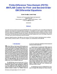
Introduction Nowadays, printed surfaces, applying FSS or EBG techniques, are characterised through their reflection phase behaviour over the frequency. In order to assess this behaviour, first the structure is exposed to a plane wave, and thereafter the phase of the incident and the reflected wave are compared. Normally, for simulation purposes, infinite size structures are considered, and the modelling of the whole structure can be derived from a single unit (EBG or FSS) cell by using periodic boundary conditions. The question is how far this also applies to real structures, which are always finite in size. Indeed, the total size of an antenna on an EBG substrate, for GPS applications, for instance, should not be too large for practical and economic uses. In this paper, a novel simulation model, based on FDTD, is presented, which allows an accurate and flexible modelling of finite size substrates. To carry out the investigation, the field solver Empire [1] was used. First, the problem to be simulated is described, and the simulation model will be presented. Thereafter, two different configurations for the analysis will be compared, followed by an error analysis, to investigate the accuracy of the FDTD modelling configurations. Finally, a finite size EBG structure will be studied using this methodology, and its results will be discussed. Description of the problem The basic idea for characterising the reflection phase of the a certain Structure Under Test (SUT) is to define a plane wave that is incident onto a finite size structure, at an arbitrary angle, and determine the reflected plane wave, as shown in figure 1. The near field components must be detected, to perform a nearfield-to-farfield transformation, and thus obtain the desired components of the diffracted field in the direction of the reflected wave. The phases of the incident and reflected waves can then be compared to determine their relative phase difference. An absolute phase difference cannot be established, as the nearfield-to-farfield transformation introduces an unknown phase offset. Etheta Etheta Angle Of incidence
Ephi
Figure 1: Plane wave excitation on the SUT.
Ephi
In order to obtain the absolute phase difference, a second simulation must be carried out. This time, the SUT is replaced by an ideal conducting plate of identical size. Again, the relative phase difference can be determined. Then, the absolute phase difference for the SUT can be calculated by normalising it to the phase difference of the metal plate. In this way, it is possible to plot the reflection phase of the SUT over the frequency, as encountered in the literature [2], [3]. FDTD modelling As mentioned in the previous section, two features have to be included in the FDTD-model: a plane wave excitation and a nearfield-to-farfield transformation. Both are defined as a boxes within the Empire FDTD-model. The nearfieldto-farfield (NF-FF) box registers the nearfields, and transform them into the farfield using Huygens’ Principle. The plane wave (PW) box is defined in such a way that the plane wave is used as an excitation, and only exists within the box, whereas outside the PW-box only the scattered fields are present. This is accomplished, in first instance, by defining fields on the appropriate surfaces of the PW-box, that generate a plane wave in its interior. In order to avoid that this plane wave exits the interior of the PW-box, equal opposite fields are defined on the faces of the box through which the plane wave would leave the box. This technique functions adequately as long as the scattering objects within the PW-box are small compared to the size of the PW-box, which do not disturb significantly the propagation of the generated plane wave. In the case of structures printed upon finite size substrates, such as FSS or EBG, the SUT will occupy a large volume within the size of the PW-box. Indeed, such structures demand very fine meshing, and it is therefore desirable to keep the discretised space as small as possible. In practise, this affects the accuracy of the PW-box model, as the presence of the SUT intercepts a great amount of the incident wave.. As this is not taken into account by the PW-box model, this results into excitation fields (error fields) actually leaking out the PW-box that should not actually be present. This, in turn, will have an influence on the nearfield values detected on the faces of the NF-FF-box, leading to inaccuracies in the simulation results. In order to overcome this problem, two different configurations are investigated, as displayed in figure 2: o o
The PW-box included within the NF-FF-box(from here on, PWFF –model). The NF-FF-box included within the PW-box (from here on FFPW-model).
The first model is based on the hypothesis that, for waves coming from the top of the PW box, most of the ‘error’ fields exit the PW-box through the bottom surface, that is almost completely shadowed by the SUT. This can be assumed for angles of incidence up to approximately 60°, if 0° represents a plane wave perpendicular to the SUT. To compensate this error when calculating the farfield, the fields on the bottom surface of the NF-FF box will be set to 0. In the second model, the plane waves, excited by the PW-box, go through, and are thus cancelled out in the farfield calculation. With this configuration, the ‘error’ fields that leak out of the PW-box are not registered by the NF-FF box, and should therefore not have any influence upon the farfield results.
Figure 2: Two different FDTD models for investigating finite size substrates using plane wave excitation.
Error analysis In order to determine which model is more accurate, a simple but effective test was performed: a metal plate was situated within both simulation setups. In each case, two different simulations were performed, with the metal plate at different heights, as shown in figure 3.The relative phase difference of the reflected wave over the frequency for the two positions of the metal plate can be easily determined analytically. Therefore, this is suitable benchmark for comparing errors introduced by the PWFF- and FFPW-models.
Figure 3:Test setup for error analysis. In figure 4, the relative reflection phase for both models is shown, for an angle of incidence of 60°. It is clearly visible that the PWFF-box configuration yields good results, yet leads to a greater error than the FFPW-model. In the case of the FFPW configuration, the difference between the simulated results and the analytical solution is negligible. This was also verified for other angles of incidence. Thus, the FFPW-model seams to be more suitable for characterisation the plane wave reflection behaviour of finite substrate structures.
Figure 4: Phase difference over frequency for the PWFF-, and FFPW-models (delta = 3 mm). Application example To show the influences of the finite size of the substrate, a mushroom EBG structure was simulated. The FFPW-model presented above was chosen. Different sizes of the structure were investigated, with different numbers of EBG cells. Figure 5 shows how a non-desired resonance appears in the structure if an insufficient number of cells is taken into account. This resonance is not present when the size of the substrate is infinite. This effect can be lessened by increasing the size of the SUT, thus including a greater number of EBG cells. In fact, for an SUT with 15 x15 cells this resonance is not present anymore. Another effect of considering a finite size substrate is a shift of the centre bandgap frequency. This centre frequency is defined by a 0° reflection phase. Figure 6 shows how this centre frequency differs from the one obtained when simulating an infinite EBG structure. To perform this comparison, Ansoft Designer, based on the Method of Moments, was used to carry out the simulation of the infinite structure. This was achieved by defining a single EBG cell, and using then periodic boundary conditions. The differences between the two curves have to be further investigated and verified through measurements.
Figure 3: Simulation of different sizes of the SUT for a mushroom structure.
Figure 6: Comparison of the simulated results obtained for a finite size structure (Empire) and an infinite size structure (Ansoft Designer) for typical mushroom EBG cells. Conclusions Two different configurations have been presented for accurately determining the reflection phase of structures with finite size substrates using the FDTD method. The behaviour of the models show a good agreement with theory. The most accurate of the two was tested with a typical EBG structure. In near future, this method will be used to further investigate the behaviour of realistic EBG structures combined with antennas. Literature [1] [2] [3]
EMPIRE User and Reference Manual, IMST GmbH, 2003. F. Yang and Y. Rahmat-Samii, ‘Reflection Phase Characterisation of the EBG Ground Plane for Low Profile Wire Antenna Applications’, IEEE Trans. on A&P, Vol. 51, NO. 10, PP. 2691-2703, October 2003 J.M. Baracco, P. de Maagt, ‘Radiating Element on a photonic bandgap structure for phased array applications’, JINA, Nice, 12-14 November, 2002