Abstract. Fuzzy logic and proportional-integral-derivative (PID) controllers are compared for use in direct current (DC) motors positioning system. A simulation ...
IJCSI International Journal of Computer Science Issues, Vol. 7, Issue 5, September 2010 ISSN (Online): 1694-0814 www.IJCSI.org
Comparison between Conventional and Fuzzy Logic PID Controllers for Controlling DC Motors Essam Natsheh1 and Khalid A. Buragga 2 1
Department of Management Information Systems, College of Applied Studies & Community Services, King Faisal University Hofuf, Al-Hassa 31982, Saudi Arabia 2
Department of Information Systems, College of Computer Sciences & IT, King Faisal University Hofuf, Al-Hassa 31982, Saudi Arabia
Abstract Fuzzy logic and proportional-integral-derivative (PID) controllers are compared for use in direct current (DC) motors positioning system. A simulation study of the PID position controller for the armature-controlled with fixed field and fieldcontrolled with fixed armature current DC motors is performed. Fuzzy rules and the inferencing mechanism of the fuzzy logic controller (FLC) are evaluated by using conventional rule-lookup tables that encode the control knowledge in a rules form. The performance assessment of the studied position controllers is based on transient response and error integral criteria. The results obtained from the FLC are not only superior in the rise time, speed fluctuations, and percent overshoot but also much better in the controller output signal structure, which is much remarkable in terms of the hardware implementation.
Keywords: Three-term controller, PID controller, fuzzy systems, fuzzy logic controller, DC Motors.
1. Introduction Lotfi Zadeh, the father of fuzzy logic, claimed that many sets in the world that surrounds us are defined by a nondistinct boundary. Zadeh decided to extend two-valued logic, defined by the binary pair {0, 1}, to the whole continuous interval [0, 1], thereby introducing a gradual transition from falsehood to truth [1]. Fuzzy control is a control method based on fuzzy logic. Just as fuzzy logic can be described simply as "computing with words rather than numbers"; fuzzy control can be described simply as "control with sentences rather than equations". A fuzzy controller can include empirical rules, and that is especially useful in operator controlled plants. A comprehensive review of the classical design and implementation of the fuzzy logic controller can be found in the literature [2], [3], [4]. A fuzzy IF-THEN rule-based system consists of the following modules [5], [6]:
Fuzzification: Converting crisp facts into fuzzy sets described by linguistic expressions. Membership functions can be flat on the top, piece-wise linear and triangle shaped, rectangular, or ramps with horizontal shoulders. Inference: The fuzzy IF-THEN rule expresses a fuzzy implication relation between the fuzzy sets of the premise and the fuzzy sets of the conclusion. The following steps describe this process: 1. Matching of the facts with the rule premises (determination of the degree of firing DOF of the facts to the rule premises). 2. If the rule contains logic connections between several premises by fuzzy AND or fuzzy OR the evaluation is performed by t-norms or t-conorms (the result gives then the DOF of the facts to the complete premise). 3. Implication: The next step is the determination of the individual rule output. The DOF of a rule interacts with its consequent to provide the output of the rule. It will be a fuzzy subset over the output universe. Aggregation: This process aggregates the individual rule outputs to obtain the overall system output. It will be also a fuzzy subset over the output universe (a union operation yields a global fuzzy set of the output). Defuzzification to obtain crisp output (various defuzzification methods can be used, as, e.g., center of gravity, bisector of area, and mean of maximum, to obtain a crisp numerical output value).
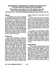
A PID-like (proportional plus integral plus derivative, PID) fuzzy logic controller (FLC), or simply PID-like FLC, algorithms have been and continue to be a very active and fruitful research field since Mamdani and Assilian pioneering work on fuzzy controller in 1974 [3]; the controller is shown in Fig. 1. The impetus behind this
128
IJCSI International Journal of Computer Science Issues, Vol. 7, Issue 5, September 2010 ISSN (Online): 1694-0814 www.IJCSI.org
continuity of the subject lies largely in the fact the conventional PID algorithms has been successfully used in the process industries since 1940s [7] and remains the most commonly used algorithm today, while numerous application of fuzzy logic control (FLC) have immerged covering a wide range of practical areas [8] and that many software and hardware products for fuzzy control have been commercialized during the last few years.
allows a novice to construct a set of membership functions for a specific linguistic variable systematically.
2.1 Ideal PID-like FLC A comprehensive review of the classical design and implementation of the ideal PID-like FLC can be found in [3], [6]. The control law can be realized by: U (k) = F (e (k), se (k), de (k))
Z -1
e (kT)
+
T
+
Z
U (k) se (kT)
-1
PID
+
1 T
FLC
de (kT)
Fig. 1 PID-like fuzzy logic controller.
Because designing methods of PID-like FLC emulates human control strategy, their principles are easy to understand for non-control specialists. During the last two decades, designing methods of conventional PID-like controller have been using more and more advanced mathematical tools. This is needed in order to solve difficult problems in a rigorous fashion. However, this also results in fewer and fewer practical engineers who can understand these design methods. Therefore, practical engineers who are on the front line of designing consumer products tend to use the approaches that are simple and easy to understand. Design method of the PID-like FLC is just such approaches. The objective of this paper is to identify and study the designing method of the PID-like FLC The remaining of this paper is organized as follows: Section 2 is presents the designing of the PID-like FLC. Comparing the performance of conventional PID and PIDlike FLC design methods using second-order armaturecontrolled DC motor and third-order field-controlled DC motor as a case studies are presented in section 3. Finally, section 4 presents the conclusion.
2. Designing the PID-Like FLC In the following section, we propose a design method for a PID-like FLC. A simple mean for designating membership functions for the PID-like FLC is presented. This method
129
(1)
where e (k), se (k) and de (k) are error, integral of error and rate of change in error, respectively; U (k) is the control action and the function F is the control law that is described by a rule-base. The reasoning algorithm translates the set of vague rules into a mapping: U (k) = f (e (k), se (k), de (k))
U k K P e k K i se k K d de k that is similar to the ideal PID control algorithm:
(2)
3
The major problem to this design method is that it is difficult to write rules for the integral action [9]. Another problem is integrator windup. Windup occurs when the actuator has limits, such as maximum speed for a motor. When the actuator saturates, the control action stays constant, but the error will continue to be integrated, the integrator winds up. The integral term may become very large and it will then take a long time to wind it down when the error changes sign. Large overshoots may be the consequence.
2.2 Rule-base Matrix of the PID-like FLC In the following we shall discuss the nature of the rules contained in the PID-like FLC rule-base. The typical response of the second-order and third-order systems is shown in Fig. 2.
IJCSI International Journal of Computer Science Issues, Vol. 7, Issue 5, September 2010 ISSN (Online): 1694-0814 www.IJCSI.org Fig. 2 The general response of the second-order and third-order systems.
According to the sign and magnitude of error e (k) and its change de (k), the response plane is roughly divided into five zones. The index used for identifying the response zones is defined as [11], [12]:
130
maintained. The rules that belong to this zone realize meta-rule 1. To design PID-like FLC, we propose three-dimensional rule-base matrix described in Table 2, where N, Z, and P are the linguistic labels negative, zero, and positive of the term sets error, change of the error, and sum of the error. Table 2: Rule-base matrix of the PID-like FLC
Z2: e < 0 and de < 0, Z1: e > 0 and de < 0, Z4: e > 0 and de > 0, Z3: e < 0 and de > 0, Z5: e 0 and de 0. So, we can identify five main homogenous zones in PIDlike FLC rule-base, as shown in Table 1, where N, Z, and P are the linguistic labels negative, zero, and positive of the term sets error, change of the error, and sum of the error.
N
N
Change of the error N Z Z Z
P
Z2
N Z P
P
P
Z3 Z5
Z1 N
Z
Z4 P
N Z P Sum of the error
N
Z
N Z P
N N N Z N
N N N Z Z
Change of the error N Z Z Z P N N N N Z N Z Z Z P Z P P P P P N Z P N Sum of the error
P Z P P Z
P Z P P P
2.3 Optimizing the Membership Functions
Table 1: State plane of the PID-like FLC rule-base
Error
Error
P
Tang and Mulholand [13] propose the following three meta-rules: MR1: If both e (k) and de (k) are zero, then maintain present control setting. MR2: If conditions are such that e (k) will go to zero at a satisfactory rate, then maintain present control setting. MR3: If e (k) is not self-correcting, then control action U(k) is not zero and depends on the sign and magnitude of e (k) and de (k). Yager and Filev [6] use these three meta-rules to analyze the general rule-bases of the FLC as follows: In zone 1 and 3 the error is self-correcting and U(k) is almost zero; that is, the control variable remains at its present setting. The rules of these zones realize meta-rule 2. In zone 2 and 4 the errors are not self-correcting and consequently negative and positive, respectively, control action U (k) applies. The magnitude of U (k) changes with respect to the magnitudes of e (k) and de (k). The rules associated with these zones are related to metarule 3. In zone 5 both e (k) and de (k) are close to zero. The system is in a steady state and U (k) is almost zero, that is, the present control setting is
In real applications of FLC, the membership functions are constructed by assembling knowledge from the experts and then modified by laboriously surveying the control response of the process. In most control cases, the FLC cannot be effective without carefully arranging the membership functions. In the theoretical analysis of the FLC, the selection of membership functions does not get much attention from the majority of researchers. Most use isosceles triangular functions with equal spans throughout the whole universe of discourse as membership functions for their FLCs [11], [12], [17]. The main advantage of choosing this type of membership function is that it eases the difficulties in analyzing the structure of the FLC. However, almost all the applications of FLC adopt non-equal span membership functions to cope with the real control problems. Instinctively, the closer the control response to the setpoint (or normal condition), the narrow the membership function range should be. For some highly nonlinear processes a FLC with equal-span triangular membership function is not adequate to achieve a good control result.
(x) negative
zero
1
U x
K x
0
positive
Kx
Ux
x
Fig. 3 Membership functions for fuzzy variable x.
IJCSI International Journal of Computer Science Issues, Vol. 7, Issue 5, September 2010 ISSN (Online): 1694-0814 www.IJCSI.org
For fuzzy variable x with universe of discourse [Ux, Ux] and three fuzzy sets negative, zero, and positive we use the membership functions shown in Fig. 3 to represent them. The problem is simplified to be the determination of Kx point in each fuzzy variable. To accomplish a better performance and to devise a systematic method to obtain optimal membership functions, we propose the following algorithm: Determine the universe of discourse Ux for each fuzzy variable; Initialize Kx value to each fuzzy variable to be Kx = Ux / 2; Initialize IAE and ITAE to large values; For i=1 to max number of epochs to refinement all Kx For j=1 to min number of epochs to refinement one Kx Run the experiment and get new_IAE and new_ITAE ; If ((new_IAE < IAE) and (new_ITAE < ITAE)) IAE = new_IAE ; ITAE = new_ITAE ; Save Kx ; End if If ((new_IAE IAE) and (new_ITAE ITAE)) Kx = Kx increase_ratio; Else Kx = Kx decrease_ratio; End if End for End for We suggest using decrease_ratio and increase_ratio as 0.9 and 1.05 respectively. IAE and ITAE are defined as follows:
Integral of the absolute of the error (IAE) defined by:
IAE e t dt
4
0
The integral of time multiplied by the absolute of error (ITAE) defined by:
ITAE t e t dt
5
0
where e (t) is the measured error. The calculation in the studies was implemented by substituting an algebraic sum for the integrals [8]. IAE accounts mainly for error at the beginning of the response and to a lesser degree for the steady state duration. ITAE keeps account of errors at the beginning but also emphasizes the steady state [10].
131
3. Performance Analysis of the PID-Like FLC 3.1 Introduction Having designed a fuzzy PID-like controller, it is important to validate its performance and compare it with conventional PID controllers. Analyzing time responses usually makes such evaluations. But simply examining the behavior of a controller is not enough to validate its performance or prove that it is better or worse than other controllers are. In the next section, we suggest using two performance measures with two simulated systems. The objectives of the simulation are to demonstrate the feasibility of the fuzzy PID-like design method when applied to second order systems and third order systems. Then we compare their performance with the performance of conventional design method. In the following section, we present the performance measures that will be used during this study. In section 3.3, we present the applications that will be used in testing and analyzing the performance. Section 3.4 presents implementation technique for the PID-like FLC. The simulation results of this controller will be presented in section 3.5.
3.2 Performance Measures To test our model, we choose to use two performance measures. These measures will be used in analyzing the performance of the PID-like FLC. They are: 1. Transient response: One of the most important characteristics of control systems is their transient response. The transient response is the response of a system as a function of time. It can be described in terms of two factors[18]: The swiftness of response, as represented by the rise-time (Tr). The closeness of the response to the desired response, as represented by the overshoot (Os) and settling-time (Ts). 2. Error integral criteria: The performance was evaluated by two frequently used error integral criteria IAE and ITAE as was described in the previous section.
3.3 Description of the Applications used in our Study Two types of direct current (DC) motors are studied to examine the performance correspond to various design methods to design PID-like FLC. DC motors are classified into several broad categories. They are described in [24]. The DC motors have
IJCSI International Journal of Computer Science Issues, Vol. 7, Issue 5, September 2010 ISSN (Online): 1694-0814 www.IJCSI.org
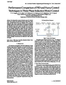
separately excited-field, in which the field winding is separate from the armature. They are either armaturecontrolled with fixed field or field-controlled with fixed armature current [16], as shown in Fig. 4.
132
where Km is motor gain constant and Tm is motor time constant. For simplicity, we assume that Km = 1 newtonm/amp and Tm = 1 second.
3.3.2 Field-controlled DC Motors Separately excited-field DC motors
Armature-controlled DC motors
The transfer function between the output angular displacement of this motor shaft (t) and its input control action U (t) is given by [16]: Km s U s s T f s 1 Tm s 1
Field-controlled DC motors
Fig. 4 Separately excited-field DC motors.
DC motors whether armature-controlled or fieldcontrolled, are used in our simulation. The block diagram of such systems is shown in Fig. 5. The control objective for both types of DC motors is to reach a specified motor position using an appropriate input drive voltage. A zero-order holder device is used to keep a constant controller output during each interval. The PID controller inputs are defined as follows: e kT setpo int t position t | t kT
6
e kT e k 1 T T
7
se kT se k 1T T e k 1T
8
de kT
here T is sampling interval time; setpoint(t) and position(t) are reference and process output that is the angular displacement of the motor shaft. Setpoint +
e (t)
e*(t)
_
PID-like FLC
U(t)
Zero-Order Hold
U*(t)
DC Motor
Output (t)
T
Fig. 5 DC Motor system with PID-like FLC.
3.3.1 Armature-controlled DC Motors Ogata [16] gives the transfer function between the output angular displacement of the motor shaft (t) and the input control action U (t): Km s U s s Tm s 1
9
10
where Km is motor gain constant, Tf is time constant of field circuit and Tm is time constant of inertia-friction element. For simplicity, we assume that Km = 1 rad/voltsec, Tf = 0.1 second and Tm = 1 second.
3.4 Implementation of the PID-like FLC For simulating the design method of PID-like FLC, we code the fuzzy inference system using C language; see appendix A. In the implementation, MIN operator is chosen as AND connective between the antecedents of the rules of the FLC and as the fuzzy implication operation, while MAX operator is chosen as OR connective between the individual rules. Center of area (COA) is chosen as defuzzification method [2], [14], which defined as: U
x x x i
i
i
i
11
i
Here xi is a running point in a discrete universe, and (xi) is its membership value in the membership function. Having defined the fuzzy linguistic control rules, the membership functions corresponding to each element in the linguistic set must be defined. We use optimal membership functions method described in the previous section to define the membership functions for e, de, se and U linguistic variables. These membership functions used for both DC motor systems types, have universe of discourse of e, de, se and U as [-50 50], [-40 40], [-100 100], and [-40 40] respectively. For designing PID-like FLC for both DC motor types, 50 radian were used as desired angular displacement of the motor shaft and sampling interval time T were used as 1 second.
IJCSI International Journal of Computer Science Issues, Vol. 7, Issue 5, September 2010 ISSN (Online): 1694-0814 www.IJCSI.org
133
3.5 Simulation Results Comparisons between step responses of armaturecontrolled DC motor and field-controlled DC motor systems using conventional PID controller and the PIDlike controller are shown in Fig. 6 and Fig. 7 respectively. Table 3 and Table 4 compares the transient response and error integral criteria of those two systems.
Fig. 7 Step response of field-controlled DC motor system using conventional and fuzzy PID controllers.
Table 4: Performance comparison of field-controlled DC motor system
Fig. 6 Step response of armature-controlled DC motor system using conventional and fuzzy PID controllers.
Table 3: Performance comparison of armature-controlled DC motor system
Using conventional PID controller Using PID-like FLC
Tr
Ts
(Sec.)
(Sec.)
Os (%)
IAE
Using conventional PID controller Using PID-like FLC
12
2.29
160.48
631.83
4
5
2.16
126.93
590.69
Throughout the experiments, we assumed the operating condition for both controllers was fixed and there were no motor parameters and motor load variations. From the running results as shown in Fig. 6 and Fig. 7, the PID-like FLC performed better than that of the conventional PID controller. Taking the conventional PID controller as a base system, Table 5 shows the percentage of improvement of PID-like FLC over conventional PID controller. From this table its shown that using the PID-like FLC with armaturecontrolled DC motor, took about 58% less time than that of conventional PID controller to reach the desired position and 43% with field-controlled DC motor system.
Ts (Sec.)
Os (%)
IAE
ITAE
8
14
7.03
246.59
1490.1
5
8
4.95
178.29
856.61
Table 5: Percentage of improvement of PID-like FLC over conventional PID controller
ITAE
7
Tr (Sec.)
Armaturecontrolled DC motor system Fieldcontrolled DC motor system
Tr
Ts
(Sec.)
(Sec.)
Os (%)
IAE
ITAE
43%
58%
6%
21%
7%
38%
43%
30%
28%
43%
The simulation results for the system with PID-like FLC shows a constant speed behavior in the steady state for both cases aforementioned. Moreover, a very fast rise time without a large overshoot and a very low percentage of speed fluctuations are also observed in the step responses when compared to the conventional PID controller cases. When the voltages obtained by the PID-like FLC in both cases are compared with the ones in conventional PID control results, an almost constant steady state behavior is observed. Indeed, a vigorous change in the controller output to be used as an input voltage to the motor as in the PID case is not realizable in a real time hardware implementation. The reason for getting such a smooth
IJCSI International Journal of Computer Science Issues, Vol. 7, Issue 5, September 2010 ISSN (Online): 1694-0814 www.IJCSI.org
controller output in the PID-like FLC case is because of the fact that PID-like FLC updates the controller output by making comparison of the error and the change of error in the angular displacement of the motor shaft. In this way, a robust and a realizable controller output signal is obtained. These observations, on the other hand, successfully demonstrate that the PID-like FLC to regulate the angular displacement of the motor shaft of a DC motors is one of the best selections in the mechanism control area.
4. Conclusions The design and implementation of armature-controlled and field-controlled DC motor system using both conventional PID and PID-like FLC have been presented. Comparisons of experimental results of the conventional PID controller and PID-like FLC show that the PID-like FLC is able to perform better than the conventional PID controller. Results indicate that even without knowing the detail of the control plants, we were able to construct a well performed fuzzy logic controller based on the experience about the position controller. Acknowledgments The authors would like to express their appreciation to Deanship of Scientific Research at King Faisal University for supporting this research.
References [1] J. Jantzen, "Tutorial on Fuzzy Logic", Technical University of Denmark: Department of Automation, Technical report number 98-E 868, 19 Aug 1998, URL: http://www.iau.dtu.dk/ [2] J. Jantzen, "Design of Fuzzy Controllers", Technical University of Denmark: Department of Automation, Technical report number 98-E 864, 19 Aug 1998, URL: http://www.iau.dtu.dk/ [3] C. C. Lee, "Fuzzy Logic in Control Systems: Fuzzy Logic Controller-Part I", IEEE Transactions on Systems, Man, and Cybernetics, Vol. 20, No. 2, pp. 404-418, 1990. [4] C. C. Lee, "Fuzzy Logic in Control Systems: Fuzzy Logic Controller-Part II", IEEE Transactions on Systems, Man, and Cybernetics, Vol. 20, No. 2, pp. 419-435, 1990. [5] R. Isermann, "On Fuzzy Logic Applications for Automatic Control, Supervision, and Fault Diagnosis", IEEE Transactions on Systems, Man, and CyberneticsPart A: Systems and Humans, Vol. SMC-28, No. 2, pp. 221-235, 1998. [6] R. R. Yager and D. P. Filev, "Essentials of Fuzzy Modeling and Control", John Wiley & Sons, 1994. [7] T. E. Marlin, "Process Control: Designing Process and Control Systems for Dynamic Performance", McGraw-Hill, 1995.
134
[8] J. Nie and D. A. Linkens, "Fuzzy-Neural Control: Principles, algorithms and applications", Prentice Hall, 1995. [9] J. Jantzen, "Tuning of Fuzzy PID Controllers", Technical University of Denmark: Department of Automation, Technical report number 98-H 871, 30 Sep 1998, URL: http://www.iau.dtu.dk/ [10] H. X. Li and H. B. Gatland, "Conventional Fuzzy Control and Its Enhancement", IEEE Transactions on Systems, Man, and CyberneticsPart B: Cybernetics, Vol. SMC-26, No. 5, pp. 791-797, 1996. [11] C. Liaw and J. Wang, "Design and Implementation of a Fuzzy Controller for a High Performance Induction Motor Drive", IEEE Transactions on Systems, Man, and Cybernetics, Vol. SMC-21, No. 4, pp. 921-929, 1991. [12] H. X. Li and H. B. Gatland, "A New Methodology for Designing a Fuzzy Logic Controller", IEEE Transactions on Systems, Man, and Cybernetics, Vol. SMC-25, No. 3, pp. 505-512, 1995. [13] K. L. Tang and R. J. Mulholland, "Comparing Fuzzy Logic with Classical Controller Designs", IEEE Transactions on Systems, Man, and Cybernetics, Vol. SMC-17, No. 6, pp. 1085-1087, 1987. [14] J. Jantzen, H. Verbruggen and J. Ostergaard, "Fuzzy Control in the Process Industry: Common Practice and Challenging Perspectives", Technical University of Denmark: Department of Automation, URL: http://www.iau.dtu.dk/ [15] B. C. Kuo, "Automatic Control Systems", Prentice-Hall, 1987. [16] K. Ogata, "Modern Control Engineering", Prentice-Hall, 1970. [17] Z. Zhao, M. Tomizuka and S. Isaka, "Fuzzy Gain Scheduling of PID Controllers", IEEE Transactions on Systems, Man, and Cybernetics, Vol. SMC-23, No. 5, pp. 1392-1398, 1993. [18] R. Dorf and R. Bishop, "Modern Control Systems", Addison-Wesley, 1995.
Essam F. Natsheh obtained his PhD in Communications and Networks Engineering from University Putra Malaysia in 2006. Currently, he is an Assistant Professor at the Management Information Systems Department, College of Applied Studies and Community Services, King Faisal University (Saudi Arabia). Essam has more than 15 years of teaching and research experiences in Malaysia and Saudi Arabia. Also, he has more than 20 publications in refereed journals at international level. His research interest is mobile ad-hoc networks, in particular, the development of a new routing algorithm for this type of networking. Khalid A. Buragga received the B.Sc. in Computer Information Systems (CIS) from King Faisal University, Saudi Arabia, and the M.Sc. in CIS from University of Miami, USA, and the Ph.D. in Information Technology from George Mason University, USA. He is currently an assistant professor at college of Computer Sc. & IT, King Faisal University. His general research interests span the areas of software design, development, quality, and reliability; business process re-engineering, integrating systems; communications, networking and signal processing.