namely, the performance of I/O interactions of host servers and storage subsystems via .... are usually best suited for the investigation of steady-state behavior.
Proceedings of the 2005 Winter Simulation Conference M. E. Kuhl, N. M. Steiger, F. B. Armstrong, and J. A. Joines, eds.
COMPONENT-BASED PERFORMANCE MODELING OF A STORAGE AREA NETWORK Nava Aizikowitz Alex Glikson Ariel Landau Bilha Mendelson Tommy Sandbank IBM Haifa Research Lab Haifa University Campus Mount Carmel Haifa, 31905, ISRAEL
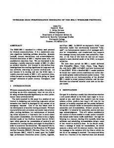
among the tiers into account. Our work focuses on performance aspects of the interaction between the application-stack tiers, and in particular, of host and storage interactions. The model captures a typical SAN environment which consists of several host servers communicating via a high-speed special-purpose network with different kinds of storage subsystems, as can be seen in Figure 1.
ABSTRACT This work explores performance issues of system-level interactions by means of performance modeling. We focus on I/O performance in a storage area network (SAN), namely, the performance of I/O interactions of host servers and storage subsystems via the SAN fabric. We present a component-based simulation performance model, which supports a rich variety of both existing and future storage subsystems, allows for some basic network configurations, and addresses the major I/O aspects of the server operating system. The model's flexibility allows for easy parameter modifications, configuration adjustments, architecture manipulations, and experimentation. The experiments presented in this paper demonstrate some of the ways this model can be utilized, such as data placement, I/O manipulation, and the evaluation of execution alternatives, and shows the types of performance insights that may be gained.
H o s t S e rv e rs
U N IX
z S e rie s
W in d o w s
S A N F a b r ic SVC ESS
D S4000
DS6000
F A S tT D riv e s
D riv e s
D riv e C o n tro lle r
D riv e s D riv e s
S to r a g e S u b s y s t e m s
1
INTRODUCTION
Figure 1: An Example of the Modeled Environment
Large systems are made up of several major tiers that interact with each other. For example, an application server (such as IBM WebSphere), working with a database server (such as IBM DB2 UDB), using the host’s operating system (such as Unix) to communicate, via a storage area network (SAN) fabric, with a storage subsystem (such as IBM Enterprise Storage Subsystem—ESS). This is generally referred as an application stack. Much is usually invested in improving the performance of each separate tier of the application stack. However, many performance problems occur, due to the poor knowledge and utilization of the I/O subsystem by the upper tiers of the application stack. By looking at the entire application stack, we can find more holistic solutions that take the interactions
Performance models are influential tools that may provide significant information for improving the interoperability of host servers and storage subsystems. We present a prototype of a component-based performance model that is easily manageable and sufficiently flexible to support a rich variety of both existing and future storage subsystems. The model enables some basic network configurations and addresses the major I/O aspects of the host operating system. The model is simulation-based and thus may express the effect on performance of unpredictable variations in business workloads. As shown in Figure 1, the entire system can comprise various types of host servers and storage subsystems. Therefore, a model of such an environment should support
2417
Aizikowitz, Glikson, Landau, Mendelson, and Sandbank a wide variety of architectures and provide the ability to deal with different types of system components. Thus, the proposed solution comprises a generic, component-based framework that captures the nature of various host servers, storage subsystems and network configurations. The framework includes generic resources, basic operations, algorithms and overheads, which are common to a wide range of architectures. On demand, the generic framework is refined for a desired architecture, by defining only the specific operations and algorithms, which will override the generic ones in the component-based environment. Some of them are embedded into the model at compile-time, and others at runtime, using a configuration mechanism. This work provides an environment for the performance evaluation of various architectures, and supports experimentation with different configuration policies and with a variety of workloads. The model can be fed concurrently by either existing real or synthetic I/O trace files, or I/O requests generated on the fly according to a given specification. We have conducted several experiments using the model to demonstrate its potential uses. Our experimentation with host and storage interactions provides insight on system-level tuning that may improve I/O performance. In particular, some of the data-manipulation experiments that improve I/O performance do not involve changes in the storage-subsystem architecture. The rest of the paper is organized as follows. Section 2 presents related work. Section 3 introduces the generic component-based framework and the model scope. Section 4 describes the model implementation, the software architecture, model flexibility, and some architecture specific considerations. Workload generation and analysis are also addressed in Section 4. Section 5 suggests experiments that utilize the model, and describes the workloads that were used. Future directions and concluding remarks are depicted in Section 6. 2
Some works (Alvarez et al. 2001, Anderson et al. 2002, Uysal et al. 2001) address monitoring, tuning and autonomic management of storage subsystems, while not taking into account the interoperability with other tiers (e.g., databases) and its impact on performance. Automatic SAN fabric design, which provides given requirements at minimum-cost, is presented in Ward et al. (2002). EMC Control Center claims to provide (as a commercial product) automatic monitoring and expert advice functions, that go beyond the storage subsystem tier (for details, see ). Merging of SAN performance management tools into the host system is also explored in Kochut et al. (2004), where performance data is collected on hosts, fabric components, and storage devices to establish baseline performance. Then, the SAN is monitored to determine all host volumes that may be troubled by performance problems. Our solution can be integrated with such an environment, to identify new and better SAN configurations. As for input modeling, extensive characterizations of server and personal-computer workloads are provided in Hsu and Smith (2003). 3
GENERIC MODELING FRAMEWORK
We regard a generic framework as a set of resources and algorithms, configured in a certain way. I/O requests are generated by the host and processed. Every request travels between different resources (and layers) of the system, using some given connectivity between them (buses, channels, etc.), data and control commands are transferred, and a response to the host is eventually generated. The exact procedure and path are determined by the system architecture, the specific configuration, and the request parameters. We have examined several architectures to find out what they have in common and what makes them unique. Figures 2, 3 and 4 present schematic diagrams of three storage subsystems: IBM Enterprise Storage Subsystem (ESS, Castets et al. 2001), IBM DS6000 (Warrick et al. 2005), and IBM SAN Volume Controller (SVC, Mellish et al. 2004). All the storage subsystems that we have considered are composed of a pair of storage management units (for higher availability)—a node and its peer, e.g., ESS clusters, DS6000 complexes, and SVC nodes. All have processors, such as ESS Symmetric Multi-Processors (denoted SMP or MP) or DS6000 CPUs, that manage the storage unit operations. All have adapters to control their interfaces: host adapters (denoted HA) that control the interface with hosts; and device adapters (DA) that control the interface with the devices (disks). All manage a cache for better I/O performance and maintain a second copy of their written data, in a non-volatile storage (NVS) of their peer, for reliability. And all use RAID functionality (explained below). But, as shown in Figures 2 and 3, ESS and DS6000
RELATED WORK
There are at least two alternative approaches for addressing system-level interactions: benchmarking on an actual environment or modeling. Building an actual environment for measurements might be an expensive approach. Moreover, a model is more flexible and amenable to modifications, and can more easily address future alternative directions. Analytic queuing models, like the ones used in Alvarez et al. (2001) and Uysal et al. (2001), and in the Disk Magic storage-configuration planning tool (Castets et al. 2003), are usually best suited for the investigation of steady-state behavior. A simulation model, on the other hand, captures the dynamic nature of real-life workloads. AMBIENCE (Wynter et al. 2004) is an automatic model building tool that integrates queuing network models with advanced inference techniques.
2418
Aizikowitz, Glikson, Landau, Mendelson, and Sandbank differ in the connectivity between their storage units and in their device layout.
between adjacent disk drives, and thus allows for many simultaneous data transfers around a loop. Whereas, the switched FC-AL technology provides for direct physical paths to each disk drive. As mentioned above, the storage subsystems that we have considered use RAID functionality. RAID, short for Redundant Array of Independent Disks, is a method whereby information is spread across several disks, to achieve redundancy, lower latency and/or higher I/O bandwidth, and recoverability from hard-disk crashes. Different types of RAID configurations may be defined. For example, RAID-5 stripes both data and parity information across all the array drives, and RAID-10 combines data striping and mirroring. ESS uses fixed-size RAID-5, whereas DS6000 utilizes flexible-size (i.e., with a variable number of disks) RAID-5 and RAID-10. The SVC, depicted in Figure 4, has some special features. In the SVC architecture, not only do the host and storage communicate via a SAN fabric, but also the communication between the storage nodes and between them and the devices occurs via the (same or distinct) SAN fabric.
Figure 2: ESS Architecture Layout
Figure 4: SVC Architecture Layout Studying different environments and understanding their basic nature led us to define generic components that support a wide variety of platforms. Our component-based approach captures the components that are common to most of the architectures, and enables easy handling of the components that are unique.
Figure 3: DS6000 Architecture Layout DS6000 uses a dedicated bus for the communication between the storage complexes, while ESS utilizes the same buses to connect between the storage clusters and between them and the host adapters. In addition, for ESS the device is organized in Serial Storage Architecture (SSA) loops, where DS6000 uses switched Fibre Channel Arbitrated Loops (FC-AL). SSA only uses the part of the loop
3.1 Generic Layout The system architecture can be divided into following generic layers:
2419
Aizikowitz, Glikson, Landau, Mendelson, and Sandbank 3.2 Generic Resources 1.
2.
3.
Host: a server or a workstation that is connected, possibly via a SAN fabric, to the channels of a storage subsystem, and consumes the logical disks provided by the storage. The host operating system includes the following layers: (a) Logical Volume Manager (LVM): maps the application's logical view of storage space to the physical view exported by the storage subsystem. (b) Disk Driver (DD): translates commands between the LVM and the physical adapter. (c) Storage Adapter (SA): an appliance responsible for sending the hosts' requests to storage, and routing responses back to the host. SAN Fabric: a storage area network fabric composed of: (a) Switch: a device that filters and forwards packets between network segments. (b) Port: an interface on the switch connected to a host, a storage node, or a device. Storage Management Node: a storage unit composed of: (a) Cache: a processing unit that maintains an internal cache, and uses (generic or specialized) adapters to interact, possibly via SAN(s), with the hosts, storage devices, and other storage nodes (peers). (b) Adapters (i) Host Adapter (HA): an appliance responsible for routing the host’s requests to the cache, and sending responses back to the host. (ii) Device Adapter (DA): an appliance that controls the access to a physical device and performs the actual read/write operations, as requested by the cache layer. (iii) Peer Adapter (PA): an appliance that handles the communication with the other storage management node (peer) that usually holds redundant copies of the written data. (c) Device: a controller of a physical storage device (typically with RAID functionality).
For the generic layers described in Section 3.1, we have identified the following generic resources. Every such resource is considered a component in our framework. • • •
• • • • • • •
•
LVM – transforms logical volume requests into physical volume requests. DD – manages the communication between the LVM and the physical adapter. SAN ports – control the interfaces of up to three different physical networks: between the host and the storage node, between the storage node and the device, or between the storage node and its peer. Channels (SAN attachments) – connect the host to the storage node, the storage node to the device, or the storage node to its peer. Adapters – control the host's interface with storage (SA) and the storage node interface with the host (HA), the device (DA), and its peer (PA). Processors – manage the storage operations (e.g., ESS SMP or SVC CPU). NVS – non-volatile memory for the peer-written data. Device – RAID controller of the managed disks. RAID ranks – RAID arrays. Buses – internal buses (e.g., HA-bus connecting the host adapter and the cache, PA-bus connecting the peer adapter and the cache, RR-bus connecting the device and the RAID ranks, etc.). Disks – disk drives.
Figure 5 depicts the layout of the generic system.
HOST
bus SAN port channel / SAN attachment
LVM
SA
HOST_SAN
NODE
As stated above, storage subsystems are usually composed of a pair of storage management nodes. The proposed model can be configured to represent several hosts and complex storage architectures comprising a larger number of (e.g., SVC) pairs, or a mixture of several storage subsystems.
HA
HA
PEER
CACHE / NVS
PA
PEER_SAN
PA
CACHE / NVS
DA
DA
DEV_SAN
DEVICE
RAID ranks
Figure 5: Generic System Architecture
2420
Aizikowitz, Glikson, Landau, Mendelson, and Sandbank Note that for a specific architecture: •
•
model, within the framework of our component-based approach. The generic basic operations are implemented in terms of the manipulation of resources. The specific architecture, the configuration, and the request parameters determine the specific sequence of resources to utilize. In a similar manner, the cache-management algorithm is actually an interface that consists of generic cache operations, such as cache-query, which rely on the architecture's cache-residency and cache-replacement policies. Most of the generic basic operations are common to a wide variety of systems (e.g., "use node processor to allocate a cache entry", "transfer 32 KB data between device and RAID rank", etc.), but some need to be refined according to the specific architecture. For example, as mentioned before, saving a copy of written data in the storage peer is done via the general HA-bus in ESS, a dedicated PA-bus in DS6000, and the SAN fabric in SVC. So, several unique implementations are provided for this basic operation.
A logical resource may be a void (or null) appliance. For example, ESS has no fabric between the storage node and the device layer. So in this case, for example, there are no device ports. Different logical resources may be mapped to the same physical appliance. For example, in ESS, the logical functions of both the HA and the PA are done by the host adapter. Also, in ESS, both the generic DA and the generic Device are part of the same physical appliance, which is called a device adapter and is denoted by DA.
3.3 Generic Parameters The model relies on a set of generic parameters. These parameters fall into two main categories: fixed overheads and overheads that depend on the size of the transferred data (typically expressed by the bandwidth of the connection). For example, for a specific channel, there is one parameter that represents the fixed service time of using the channel, and another parameter, the channel bandwidth, that infers the variable data transfer time (the division of the amount of transferred data by the channel bandwidth). Our model relies on the provision of the specific overheads for each of the modeled architectures. When dealing with a specific architecture, some of the overheads can be non-relevant, or zero. A specific configuration will determine the values that can cause the model to ignore some overheads, or to unify several overheads into a single one.
3.5 Model Scope Using generic resources and basic operations as building blocks, our component-based approach enables the composition of various environments. In the subsections below, we describe the scope of the host servers, fabric and storage architectures, and configurations that are currently covered by our model. 3.5.1 Storage Subsystem Modeling The generic components of our model capture a variety of storage configurations: several models of the established ESS (model F and model 800), a prototype of the more recent DS6000 architecture, and the essence of the SVC unique design. Currently, the model handles different layouts of storage devices (e.g., SSA loops and switched FCAL enclosures), and copes with different RAID levels (e.g., RAID-5 and RAID-10).
3.4 Generic Algorithms and Basic Operations The transaction-flow modeling is divided into four main algorithms that are common to most environments: read and write (also called fast write) for requests that originate from hosts, and prestage and destage for background asynchronous operations that are generated by the storage subsystem. The read algorithm deals with the processing of read requests, including both cache hits and data staging due to cache misses. The (fast) write algorithm deals with the writing of data into storage node cache and into the peer’s non-volatile storage. The prestage algorithm takes care of the prefetching of data from a device into storage cache—triggered by known patterns (e.g., the number of address-sequential reads in a row). The destage algorithm handles the flushing of cached-written data to storage devices—triggered by cache (or non-volatile storage) thresholds. We have developed these four basic algorithms in terms of generic, basic operations, whose implementations might be exchangeable in different architectures or configurations. Actually, every such implementation of a generic basic operation can be viewed as a component of the
3.5.2 Fabric Modeling The model can be configured to transfer requests through a SAN or via direct attachments. The SAN is modeled as a set of SAN ports and Fibre Channel Protocol (FCP) attachments (Meggyesi 1994). Each port is attached to a host, to a storage node, or to a device. The model currently copes with SAN configurations with a single layer of switches. Every time a request is transferred through the SAN, the source and the destination ports, as well as the corresponding channels, are held until a packet is transferred. Note that the bandwidth of the SAN fabric is assumed to be large enough, and thus is not taken into account, and that the SAN latency is ignored.
2421
Aizikowitz, Glikson, Landau, Mendelson, and Sandbank 3.5.3 Host Server Modeling Aspects
•
The model assumes Open System hosts. The host operating system is modeled by LVM, i.e., an entity that translates the application logical view to the physical view exported by the storage subsystem (e.g., IBM AIX’s LVM), a disk– driver layer, and a physical-adapter layer. The assumption is that the LVM translation may involve the manipulation of I/O requests; namely, the splitting of I/O transactions and routing of I/O requests via different paths. On the other hand, disk-driver operations may involve I/O coalescing. The physical adapters control the host interface with the storage subsystem and are called storage adapters (SA).
• • •
4
Architecture
RAID Rank
Statistics
The model is a simulation-based queuing model, written in C++, and built on top of the CSIM18 simulation engine (). The model supports multiple storage subsystems and multiple hosts that compete for the fabric resources to transfer I/O requests and responses. The model is trace driven. The trace can be either an existing static real or synthetic I/O trace file, or a dynamic I/O stream generated on the fly. Each I/O request holds the following attributes: request type (i.e., read or write), target address (logical disk and logical block address), data amount, and timestamp. The model output includes detailed per-resource statistics (utilization, interarrival time, service time, queue length, etc.), and configurable statistical output such as transaction response time, data throughput, and cache-hit rates.
CSIM
• • • • •
Configuration Reader
Cache
Input Trace Reader
Trace Gen
As mentioned before, some particular aspects of a specific architecture may require a special treatment that refines the general framework. In these cases, the generic basic operations will be replaced by a specific version of corresponding component. For example: •
• •
The model consists of the following main software components (modules) as presented in Figure 6.
•
Configuration
Request
Figure 6: Model Software Architecture Overview
4.1 Model Software Architecture
•
Operations
Topology
COMPONENT-BASED MODEL IMPLEMENTATION
•
Operations – handles basic operations; uses Topology to determine the relevant set of resources. Cache – manages the cache. Raid Rank – performs low-level RAID access. Statistics – gathers performance information (using CSIM simulation tool mechanisms).
The basic operation of saving a copy of written data in the peer storage node is done via the HAbus in ESS, via a dedicated bus—PA-bus—in DS6000, and via the SAN fabric attachments in the SVC architecture. Differences in disks layouts, e.g., ESS SSA loops vs. DS6000 switched FC-AL enclosures. ESS fixed-size RAID-5 arrays vs. DS6000 flexible-size RAID-5 and RAID-10 arrays.
4.2 Model Flexibility
Configuration Reader – reads model parameters from configuration files. Configuration – manages the runtime configuration parameters. Trace Reader – reads requests from existing trace files. Trace Generator – generates requests on the fly. Input – retrieves requests from either the Trace Reader (static trace files) or the Trace Generator (dynamically generated I/O). Architecture – contains the architecture characteristics per model (storages, fabric, and hosts). Request – handles the request with the appropriate algorithm (e.g., read hit, write miss, etc.). Topology – determines the specific resources to be used in the processing of the current request (e.g., which host adapter to use).
The model flexibility allows for: • • • •
2422
Trivial parameter modification (e.g., the setting of operation overheads, number of host adapters, cache size, etc.). Flexible configuration adjustment (e.g., RAID-5 and RAID-10 combinations, mapping of logical disks to RAID ranks, etc.). Easy architecture manipulation (e.g., NVS access via different paths—ESS vs. DS6000, variety of drives' connectivity—SSA vs. FC-AL, etc.). Ease of experimentation.
Aizikowitz, Glikson, Landau, Mendelson, and Sandbank Note that no compilation is required when manipulating existing components and parameters, and that a new component requires only its specific modeling.
whereas a write miss is handled locally in the storage cache). More sophisticated ways to utilize the model are described in the experiments below. Some of the performance insights gained are illustrated in Section 5.3 below.
4.3 Workload Generation and Analysis 5.2.1 Data Placement Obtaining typical I/O workloads is not trivial. Moreover, there is a need for workloads that stress the storage subsystem, for custom-made I/O traces for specific experiments, and for I/O traces that anticipate future workloads. Therefore, a tool for generating a variety of synthetic I/O trace files is essential for experimenting with our storageperformance model. Our framework includes trace-generation and traceanalysis tools. The trace generator creates an I/O stream according to a set of workload parameters, while the analyzer extracts the parameters that characterize a given trace. The trace parameters hold general values (e.g., the total number of logical disks) and per-logical-disk values (e.g., read/write ratio, sequentiality attributes, and interarrival distribution functions). Note that the trace generator may use parameters inferred by the trace analyzer to produce I/O traces with the same workload characteristics. 5
The placement of logical disks on storage devices has great impact on I/O performance. Although data placement changes are considered expensive and thus rare, it seems that storage virtualization will make data placement changes more feasible. Our model can be used to evaluate several data placement alternatives and choose the one with better I/O performance. We have experimented with several configurations of mapping logical disks to (ESS) RAID ranks to maximize the parallelism of I/O operations and improve I/O performance. For a given workload, we created a base placement of volumes, taking into consideration the total number of transactions per logical disk. Next, we did the distribution and balancing according to the total amount of data transferred per each logical disk. And finally, we split highly intensive logical disks and placed them across different RAID ranks. As expected, balancing the workload improved the I/O performance relative to the base data placement. Splitting the highly intensive volumes provided further performance improvements.
EXPERIMENTATION
We have conducted several experiments to demonstrate the model’s ease of use, and a variety of ways in which the model can be utilized. Presented below are the workloads that were used, and experiments with several configuration policies—data placement of logical disks, manipulation of I/O requests, and evaluation of different execution alternatives.
5.2.2 I/O Manipulation As mentioned before, the operating system may manipulate I/O requests by splitting them (at the LVM) or coalescing them (at the DD). The question is whether those manipulations result in I/O requests and amounts that are better for I/O performance. On one hand, coalescing may improve performance by reducing the overhead per I/O request. But on the other hand, waiting for requests to accumulate may cause delays that may degrade overall I/O performance. Experimenting with splitting and coalescing may provide some insight on these trade-offs. We defined a join policy that unites a sequence of I/O requests of the same type into a single one. The joined requests should belong to the same operating system function call, must be “close in space” (the addresses they access must be within some predefined range, e.g., one track), must be “close in time” (their timestamps should be within some specified range, e.g., one millisecond), and their combined amount should not exceed some given threshold. The joint request has the target address of the first request and the timestamp of the last request; its amount is the sum of the amounts of the joint requests. We experimented with this join policy, applied it to I/O traces, and evaluated its impact on I/O performance.
5.1 Workloads The model input workload can be any mixture of existing (real or synthetic) trace files and trace streams generated on the fly. We have experimented with I/O trace files available from the Storage Performance Council (SPC) (), and with trace files (collected by the AIX trace facility) of DB2 UDB and Oracle database servers, running the TPC-C and TPC-H benchmarks. 5.2 Experiments A trivial way to experiment with the model is to “play” with the model parameters and evaluate the impact on I/O performance. For instance, setting the number of RAID ranks, decreasing channel bandwidth, modifying resource overheads, etc. For example, as expected, increasing the storage cache size improved the I/O performance of read requests and had a minor effect on the writes (as a read miss implies accessing a relatively slow storage device,
2423
Aizikowitz, Glikson, Landau, Mendelson, and Sandbank Our experimentation shows that joining I/O requests may improve performance, especially if the join is done in multiples of the storage stripe size (i.e., the size of a disk track, times the number of disks in a RAID array). The results indicate that such system-level I/O-heuristics (which may be implemented by a hardware or a software “mediator”) can significantly improve the system performance.
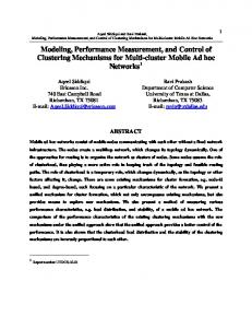
5.3 Results The results of the data placement and request-join experiments are presented in Figure 7. For this model configuration, the five SPC traces WebSearch1, WebSearch2, WebSearch3, Financial1 and Financial2 (which are available at ) represent the workloads of five hosts that are attached to an ESS model F storage subsystem, via a switch. A base data placement was created by some reasonable placement that took into account the number of transactions per logical disk. Careful balancing of the volumes according to their amount improved the read performance by 13% with respect to the base data placement. The SPC traces WebSearch1, WebSearch2 and WebSearch3 contain requests, originating at eighteen logical disks (most of them are read requests), though the great majority come from just nine of the disks. We have, furthermore, experimented with data placement by splitting these nine I/O-intensive volumes, and placing the splits on separate physical devices. This resulted in performance improvement of an additional 2%. Applying the join policy to the base data-placement above resulted in about 17% improvement in read response time. Applying the join together with the more sophisticated data-placement policies (based on request amounts and request splits) resulted in an additional reduction of the read response times by 14% and 16% respectively. Note that in the experiment above, the simulationbased model is much faster than real-life systems. Executing about 20 million SPC I/O transactions, which span over 12 hours of actual recording, took the model about 30 minutes to simulate (on a 1 GHz 2-way Pentium III processor).
5.2.3 Execution Manipulation
Total Read Response Time (Normalized)
The model enables easy manipulation of generic algorithms. As an example, the implementation and evaluation of different execution alternatives of certain copy-services functions, and in particular, one such function called flash copy, are discussed below. Flash copy provides an instantaneous (virtual) copy of what the logical-disk’s original data looked like at a specific point in time. When flash copy is invoked, only certain metadata is created at the target, and the source data is (optionally) copied in the background. Flash copy uses bitmaps to keep track of write attempts into locations within the source. Write attempts to places that were not physically copied into the target yet are put on hold, so they won't destroy the source. Then, the original data at these source locations is copied into the target. Finally, the held write requests are resumed and new data is written into the source. In order to try to get a better understanding of the impact of performing a flash copy (synchronously) in a switch vs. doing it (asynchronously) inside the storage subsystem, these two scenarios were modeled. In the synchronous case, write requests received special handling. Once a write-into-source request is identified, it is held and the flash copy is handled by the following sequence of basic operations: read original data from source; write original data to target; resume the original write. In the asynchronous case, the destage algorithm was modified similarly. A destage-into-source is held while the following sequence of basic operations is executed: stage original data from source; destage original data to target; and resume the original destage. The component-based model enables easy tailoring of these new algorithms, based on the existing implementations of basic operations. The experimentation strengthened the straightforward intuition that doing flash copy asynchronously in the storage system implies better I/O response times than doing it synchronously in the switch. For write requests, when flash copy was performed synchronously, we saw strong correlation between response times and the ratio between the number of writes-into-source and the total number of write requests. Sometimes, read performance was better when the flash copy was performed synchronously in a switch. We believe this is due to an increase in prestage operations.
1.200 1.000
1.000 0.870 0.852
0.800
0.828 0.727
0.691
0.600 0.400 0.200 0.000 No Join Base
Data Placement
Join Data Placement + Split
Figure 7: Data Placement and Join for SPC Trace Files In addition, we ran some experiments on a TPC-H I/O trace of DB2 UDB, taken both at the LVM and the DD levels. The workload was generated by an AIX host attached directly to ESS model 800 storage subsystem. We found that the device driver typically “joins” (or coalesces) eight 32KB LVM requests into a single 256KB request.
2424
Aizikowitz, Glikson, Landau, Mendelson, and Sandbank
Total Read Response Time (Normalized)
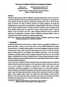
The traces were obtained against RAID-5 disk arrays of six data disks (plus one parity disk and one spare disk) each. In experiments where twelve, sixteen, or twenty four requests were coalesced into a single request showed improvements, in total read response time, of 11.2%, 9.3%, and 15.1% respectively (compared to the original DD-level trace), as shown in Figure 8. Thus, according to our experimentation, joining requests in multiples of stripes appears to be beneficial.
Kwai Wong, John D. Ponder, Greg R. Mewhinney, John G. Aschoff, Michael Factor, Danny Fishkov and Barak Mandelovich. REFERENCES Alvarez, G. A., E. Borowsky, S. Go, T. H. Romer, R. Becker-Szendy, R. Golding, A. Merchant, M. Spasojevic, A. Veitch, J. Wilkes. 2001. Minerva: An automated resource provisioning tool for large-scale storage systems, ACM Transactions on Computer Systems 19: 483-518. Anderson, E., M. Hobbs, K. Keeton, S. Spence, M. Uysal, A. Veitch. 2002. Hippodrome: Running circles around storage administration. In Proceedings of the FAST '02 Conference on File and Storage Technologies, ed. Darrell D. E. Long, 175-188. USENIX. Castets, G. A., D. Leplaideur, J. A. Bras, J. Galang. 2001. IBM Enterprise Storage Server. IBM Corporation. Castets, G., S. C. Baquero, P. Clifton, D. Laing, J. Myyryläinen. 2003. IBM TotalStorage Enterprise Storage Server model 800 performance monitoring and tuning guide. IBM Corporation. Hsu, W. W. and A. J. Smith. 2003. Characteristics of I/O traffic in personal computer and server workloads, IBM Systems Journal 42: 347-372. Kochut, A., N. Bobroff, K. Beaty, G. Kar. 2004. Management issues in storage area networks: Detection and isolation of performance problems. In 10th IEEE/IFIP Network Operations and Management Symposium 1: 453-466. Meggyesi, Z. 1994. Fibre channel overview. CERN. . Mellish, B., M. Amanat, A. Hiriyannappa, J. M. Leite. 2004. IBM TotalStorage SAN volume controller and SAN integration server. IBM Corporation. Uysal, M., G. A. Alvarez, A. Merchant. 2001. A modular, analytical throughput model for modern disk arrays. In 9th International Workshop on Modeling, Analysis, and Simulation of Computer and Telecommunication Systems, 183-192. IEEE Computer Society. Ward, J., M. O’Sullivan, T. Shahoumian, J. Wilkes. 2002. Appia: Automatic storage area network fabric design. In Proceedings of the FAST '02 Conference on File and Storage Technologies, ed. Darrell D. E. Long, 203-217. USENIX Warrick, C., O. Alluis, W. Bauer, H. Blaschek, A. Fourie, J. A. Garay, T. Knobloch, D. Laing, C. O’Sullivan, T. Rothenwaldt, T. Sano, J. N. Tang, A. Warmuth, R. Wolf. 2005. The IBM TotalStorage DS6000 series: Concepts and architecture. IBM Corporation. Wynter, L., C. H. Xia, F. Zhang. 2004. Parameter inference of queueing models for IT systems using end-to-end measurements. In Proceedings of the International
1.050 1.000
1.000
0.950 0.888
0.900
0.907 0.849
0.850 0.800 0.750 8x32KB
12x32KB
16x32KB
24x32KB
Join Size
Figure 8: Join of TPC-H Trace Files 6
CONCLUDING REMARKS AND FUTURE DIRECTIONS
The work presented in this paper provides an environment for performance evaluation of various architectures, and supports experimentation with different configuration policies and with a variety of workloads. The presented simulation-based performance model copes with host server I/O aspects, addresses basic SAN-fabric issues, and captures major storage architectures and a rich variety of configurations. A tool of this kind can aid in the evaluation of "whatif" scenarios (e.g., what will be the effect of a new given data placement on the average read response time?), and later help in finding the best solution or configuration (e.g., the optimal data placement). The component-based approach enables easy extensions of the model to cover new architectures and configurations. For example, the extension of the host model to include I/O virtualization will enable the evaluation of the resulting impact on overall SAN performance. Furthermore, the inclusion of host-I/O aspects in the model enables further research of new scenarios of host and storage collaboration, such as host and storage resource-sharing (e.g., sharing of processing power and/or cachingmemory). ACKNOWLEDGMENTS We would like to thank the following IBM colleagues for providing us with valuable data, information and insight:
2425
Aizikowitz, Glikson, Landau, Mendelson, and Sandbank BILHA MENDELSON is the manager of the Code Optimization Technology department in the IBM Haifa Research Lab, Israel. Since joining IBM in 1990, she has been developing optimizations for the DSP compiler and for the AS/400 optimizing translator. She received a B.Sc. and an M.Sc. in Computer Science from the Technion, Israel Institute of Technology, and a Ph.D. in Computer Engineering from the University of Massachusetts at Amherst. She holds several patents primarily in the area of code optimization. Her areas of interest include code optimization algorithms, compiler technology, computer architecture, and performance improvement issues. Her e-mail address is .
Conference on Measurements and Modeling of Computer Systems, SIGMETRICS 2004, ed. E. G. Coffman Jr., Z. Liu, and A. Merchant, 408-409. Association for Computing Machinery. AUTHOR BIOGRAPHIES NAVA AIZIKOWITZ is a research staff member in the IBM Haifa Research Lab, Israel, since 1992. Her areas of interest include performance modeling, code optimization and job scheduling. She has a B.Sc. in Computer Science and an M.Sc. and a D.Sc. in Operations Research from the Technion, Israel Institute of Technology. She holds several patents primarily in the area of code optimization. Her email address is .
TOMMY SANDBANK is a research staff member in the IBM Haifa Research Lab, Israel. Since joining IBM in 2003, he has been working on performance modeling and code optimization projects. He has a B.Sc. in Software Engineering from the Technion, Israel Institute of Technology (2004). His e-mail address is .
ALEX GLIKSON is a research staff member in the IBM Haifa Research Lab, Israel. During last few years, he has been working on performance modeling and systems management projects. He has an M.Sc. in Computer Science from the Technion, Israel Institute of Technology (2003). His e-mail address is . ARIEL LANDAU is a research staff member in the IBM Haifa Research Lab, Israel. Since joining IBM in 1997, he has been working on performance modeling, performance monitoring, and dynamic instrumentation projects. He has an M.Sc. in Mathematics from the Technion, Israel Institute of Technology (1997). His e-mail address is .
2426