3. Interfaces
Poster
CORIOLIS MASS FLOW AND DENSITY SENSOR ACTUATION USING A PHASE-LOCKED LOOP D. Alveringh1 , T.V.P. Schut1 , R.J. Wiegerink1 , and J.C. Lötters1,2 1 MESA+ Institute for Nanotechnology, University of Twente, Enschede, The Netherlands 2 Bronkhorst High-Tech BV, Ruurlo, The Netherlands ABSTRACT This paper reports on novel feedback based actuation electronics that use the voltage from the induction track of a Coriolis mass flow sensor as input signal for a phase-locked loop. The phase-locked loop consists of a phase detector that measures the difference between the actuation voltage and the induction voltage from the Coriolis mass flow sensor. A voltage controlled oscillator is directly tuned by this phase mismatch and synthesizes an harmonic signal for actuation. Therefore, the frequency of the signal synthesized by the phaselocked loop will gradually be adjusted to the resonance frequency of the Coriolis mass flow sensor, making it more robust to disturbances. Besides, waveform shape and amplitude can be easily altered. First experimental results show that the phase-locked loop controls the frequency as a function of density for different fluids. Stability is tested for nitrogen and shows a standard deviation of 0.148 18 Hz for 20 ks.
KEYWORDS Coriolis mass flow sensor, density sensor, phase locked loop, actuation, resonance.
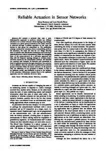
INTRODUCTION A first of its kind Coriolis mass flow sensor based on surface channel technology has been realized by Haneveld et al. [1] This Coriolis mass flow sensor is actuated in twist mode by supplying it with a varying electrical signal, inducing Lorentz forces as a result of an externally applied magnetic field. A fluid flow forces the Coriolis mass flow sensor to move in swing mode too; this effect is used to sense the mass flow. Figure 1 shows an illustration of both the twist mode due to actuation and the swing mode due to the Coriolos force. The mechanical resonance frequency of the actuated structure depends on the modal stiffness and on the modal mass. Latter depends on the mass of the channel and the mass of the fluid inside. This means that the Coriolis mass flow sensor can also be used as a density sensor, as long as the resonance frequency can be detected.
FC
FA i
Φ
ωA ωA FA twist mode (due to actuation)
swing mode (due to Coriolis force)
Figure 1: The Coriolis mass flow sensor is actuated in twist mode using Lorentz actuation. When a fluid flows through the channel, a swing mode is induced. The ratio between the two modes is a measure for the mass flow. The resonance frequency of the structure is dependent on the density of the fluid.
In the first generation of actuation electronics, the frequency is tuned to the resonance frequency by hand. Since the frequency changes with the density of the fluid inside the channels, an electronic feedback system has been designed that uses the output signal from the Coriolis mass flow sensor to tune the oscillator to the resonance frequency (second generation). In the third generation of this Coriolis mass flow sensor actuation electronics, the induction voltage of an extra metal track on the Coriolis mass flow sensor is amplified and used for actuation [2]. In spite of the convenience and performance improvements with these actuation circuits, there are still multiple drawbacks on these technologies. • A mechanical disturbance, e.g. vibration, of the Coriolis mass flow sensor will influence the actuation directly. • A fluidic disturbance, e.g. air bubble, instantly changes the actuation frequency for a short time. • The analog circuit amplifies the signal rather than synthesizes it, i.e. the signal is not harmonic. Synthesizing the actuation signal in a controlled way would help overcome these drawbacks. This is done for high frequencies for telecommunication applications with a phase-locked loop [3]. Phase-locked loops are also used for controlled actuation of servo motors [4]. This paper describes the first results of actuation of a Coriolis mass flow sensor using a phase-locked loop.
The 3rd Conference on MicroFluidic Handling Systems, 4–6 October 2017, Enschede, The Netherlands
102
THEORY A basic phase-locked loop consists of three components as is illustrated in Figure 2. First, a phase detector finds the phase difference between the output signal So (t) and the input signal Si (t). The input signal can be modeled as an harmonic signal with ωi the frequency and φi the phase: Si (t) = Sa,i · sin(ωi t + φi ),
(1)
The detected phase difference is then: (2)
φe = φi − φo ,
and could be seen as the error that the phase-locked loop needs to solve. The second component is a low-pass filter. It filters a possible ripple on the phase difference caused by the phase detector and disturbances from the input signal. The last component is a voltage controlled oscillator. This oscillator synthesizes a periodic signal with a frequency dependent on the input. The voltage controlled oscillator always provides an output signal at a frequency, also when no input is given. This is called the quiescent frequency. The output frequency ωo of the signal is: ω o = ω 0 + K · φe , (3) with ω0 the quiescent frequency and K the sensitivity of the voltage controlled oscillator. The output signal is therefore equal to: So (t) = Sa,o · sin((ω0 + K · φe )t + φo ).
DESIGN The chip (Figure 4) is adhesively mounted on a printed circuit board. Fluid inlet and outlet are connected at the backside of the board where a constant mass flow of fluid is applied (Figure 3). magnet printed circuit board
wire bond
fluid inlet
5 bar N2 reservoir with IPA/H2O
magnet
chip fluid outlet
Φ mass flow controller
Figure 3: Illustration of the chip assembly on a printed circuit board and its interface to the fluidic measurement setup.
The tested Coriolis mass flow sensor has multiple metal tracks on the channel as can be seen in the scanning electron microscopy close-up in Figure 4. One metal track is used to apply the actuation current, another is used to detect the induced voltage due to actuation. The induction track is connected to a differential amplifier with high input impedance.
(4)
Si(t) ωi ϕi
Δϕ
voltage controlled oscillator
loop filter
phase detector
Note that the frequency of the output signal is corrected based on the phase difference between output and input signal. This means that not only the output frequency will approach the input frequency, but the phases will be synchronized as well.
ϕe
ϕe
VCO
Figure 4: Photograph of the chip with close-up of the suspended channel with multiple metal tracks of the Coriolis mass flow sensor.
So(t) ωo ϕo
Figure 2: Basic phase-locked loop consisting of a phase detector, a low-pass filter and a voltage controlled oscillator. The phase detector measures the difference between the output and input signal. The voltage controlled oscillator is directly tuned by this phase mismatch and synthesizes an harmonic signal that is synchronized with the input signal.
The phase-locked loop is realized using a Cypress Semiconductor PSoC 5 development kit and is based on the work of De Lima Fernandes [5]. This development kit has a programmable system on chip with digital and analog electronic components. Figure 5 shows an overview of the phase-locked loop implementation in the programmable system on chip.
The 3rd Conference on MicroFluidic Handling Systems, 4–6 October 2017, Enschede, The Netherlands
103
and so:
Coriolis mass flow sensor
Vvco,i = amplifier
(7)
An embedded flip-flop is used to force the duty cycle of the output signal to be 50 %. An embedded signal synthesizer is used to synthesize a sine wave for the actuation voltage of the Coriolis mass flow sensor. Figure 6 shows a photograph of the full electronic setup.
comparator
chip interface board
bias
comparator
Vvco,i ivco t ω0 1 . → = = C 2π t C ivco
low-pass amplifier VCO filter Figure 5: Implementation of the phase-locked loop with the connections to the Coriolis mass flow sensor in a programmable system on chip. XOR
An embedded analog comparator converts the signal to a square wave to make it compatible with digital electronics. An XOR-gate compares the square wave with the synthesized output of the phase-locked loop. This stage performs the phase detection: the XOR-gate gives a pulse at every sample when the square wave from the induction track is not equal to the synthesized actuation voltage. After a full period, the XOR-gate gives a signal with more high values at its output when the phases are more different. The output of the XORgate is connected to a low-pass filter, which provides an analog signal that is a measure for the phase mismatch. This first order low-pass filter is implemented using an embedded operational amplifier with an external capacitor and resistor, tuned for a cut off frequency of approximately 1 Hz. The input of the voltage controlled oscillator is connected to a bias voltage generator to set the quiescent frequency. The bias voltage generator is realized using an embedded operational amplifier. The voltage controlled oscillator with output voltage Vvco,o is implemented as an embedded current source i vco that charges an external capacitor C: Vvco,o
1 = C
Z
ivco dt =
ivco t . C
(5)
An embedded comparator connects the capacitor to ground when the threshold, equal to the input of the voltage controlled oscillator Vvco,i , is reached: Vvco,o = Vvco,i ,
(6)
CMFS chip PLL to CMFS
CMFS to PLL debug screen
PLL board analog breakout components
programmable system on chip
Figure 6: Photograph of the electronic phase-locked loop implementation. The Coriolis mass flow sensor (CMFS) is located in the center on the chip interface board. The phase-locked loop (PLL) is realized on the PLL board in the programmable system on chip and
MEASUREMENTS To test the phase-locked loop for Coriolis mass flow sensor actuation, multiple fluids are applied to the sensor and the frequencies are recorded using a Keysight 34461A multimeter. The experiments are conducted
The 3rd Conference on MicroFluidic Handling Systems, 4–6 October 2017, Enschede, The Netherlands
104
with nitrogen, water, isopropyl alcohol and a mix of isopropyl alcohol and water (equal volume). The results are plotted in Figure 7 and show that the actuation circuit adjusts the frequency to the resonance frequency of the Coriolis mass flow sensor. The stability is investigated by finding the mean and standard deviation of 5001 measurements in approximately 20 ks for nitrogen. The mean is 2672.546 Hz and the standard deviation is 0.148 18 Hz, calculated from the data in Figure 8.
controls the frequency for nitrogen, water, isopropyl alcohol and a mixture of water and isopropyl alcohol. In contrast with other actuation methods, it can be fine tuned to make the actuation of the Coriolis mass flow sensor be more robust against disturbances or lower the response time. Besides, waveform shape and amplitude can be easily altered. Future work will focus on quantitative analysis through measurements of the performance of the PLL compared to the conventional actuation circuits.
2800
2200 2000
IPA IPA+Water Water
Frequency (Hz)
2400
ACKNOWLEDGEMENTS The authors gratefully acknowledge support by the Eurostars Programme through the TIPICAL project (E!8264) and technical support by R.G.P. Sanders and J. Groenesteijn.
Nitrogen
2600
1800 1600
[2]
1400
0
200 400 600 800 1000 Density (kg m−3 )
Figure 7: Measured resonance frequencies for four different substances.
Frequency (Hz)
[1]
[3]
2673.2
[4]
2672.8
[5]
2672.4
CONTACT * D. Alveringh,
[email protected]
2672.0 2671.6
REFERENCES J. Haneveld et al., “Modeling, design, fabrication and characterization of a micro Coriolis mass flow sensor,” Journal of Micromechanics and Microengineering, vol. 20, no. 12, p. 125001, 2010. J. Groenesteijn, “Microfluidic platform for Coriolis-based sensor and actuator systems,” Ph.D. dissertation, University of Twente, Enschede, January 2016. G.-C. Hsieh et al., “Phase-locked loop techniques. a survey,” IEEE Transactions on industrial electronics, vol. 43, no. 6, pp. 609–615, 1996. G. Volpe, “A phase-locked loop control system for a synchronous motor,” IEEE Transactions on Automatic Control, vol. 15, no. 1, pp. 88–95, 1970. A. De Lima Fernandes, “Demystifying the PLL,” 2013.
0
4
8 12 Time (ks)
16
20
Figure 8: Stability measurement of 5001 samples (20 ks) for nitrogen with constant pressure and mass flow.
CONCLUSION A phase-locked loop is realized to actuate a Coriolis mass flow sensor at its resonance frequency. First experimental results show that the phase-locked loop The 3rd Conference on MicroFluidic Handling Systems, 4–6 October 2017, Enschede, The Netherlands
105