1660
IEEE JOURNAL ON SELECTED AREAS IN COMMUNICATIONS, VOL. 17, NO. 9, SEPTEMBER 1999
Delay and Synchronization Control Middleware to Support Real-Time Multimedia Services over Wireless PCS Networks Hang Liu and Magda El Zarki, Member, IEEE
Abstract—This paper presents a discussion of several middleware design issues related to the support of real-time multimedia communications over wireless personal communication services (PCS) networks. Specific interests are given to error recovery and synchronization mechanisms. A hybrid automatic repeat request (ARQ) scheme is employed for error control in the proposed system because it can efficiently adapt to nonstationary wireless channels and yield high throughput and reliability. In particular, delay and delay jitter control related to retransmissions in the error control module are addressed. An adaptive source rate control mechanism is used to handle the fluctuation of the effective channel data rate due to retransmissions. An adaptive synchronization scheme is developed to compensate for long-term delay variation caused by large-scale fading so that synchronization is preserved and end-to-end delay is kept low. Simulation results from the performance evaluation of the system are presented. Index Terms—Adaptive source rate control, delay, delay jitter, hybrid automatic repeat request (ARQ), personal communication service (PCS) networks, real-time multimedia services, and synchronization.
I. INTRODUCTION
I
N recent years, wireless personal communication services (PCS) networks based on digital technologies have attracted a lot of attention [1]. Although these networks initially focus on voice and data applications, wireless users are requiring a wider range of communication services involving video and multimedia. The enormous growth in applications leads to the development of new service enabling platforms to support multimedia services, in particular the delivery of real-time video, over PCS networks. Multimedia services require high transmission reliability and stringent end-to-end delay. Wireless links on the other hand are error prone, band limited, and time varying. Both the quality-of-service (QoS) requirements and the characteristics of wireless networks should be considered in the development of a service enabling platform for multimedia services over wireless PCS networks. For example, error recovery mechanisms can be employed in the platform to achieve
Manuscript received May 1, 1998; revised April 1, 1999. H. Liu is with C&C Research Laboratories, NEC USA, Inc., Princeton, NJ 08540 USA (e-mail:
[email protected]). M. El Zarki is with the Department of Electrical Engineering, University of Pennsylvania, Philadelphia, PA 19104 USA (e-mail:
[email protected]). Publisher Item Identifier S 0733-8716(99)05596-1.
high communication reliability, and synchronization can be preserved with delay and synchronization control mechanisms. These mechanisms interact to provide good QoS support for wireless multimedia communications. A wireless communication system experiences both smallscale (multipath) and large-scale (shadowing) fades [2]. Error control mechanisms are necessary to provide high reliability required by multimedia communications. Traditionally, forward error correction (FEC) codes have been used for real-time communication services because they maintain a constant throughput and a bounded delay. Wireless links are time varying. FEC codes can be chosen to guarantee certain error rate requirements for the worst channel conditions. However, this causes unnecessary overhead and wastes bandwidth when the channel is in good state. Recently, for wireless environments, it has been shown that automatic repeat request (ARQ) and hybrid ARQ schemes can significantly improve the transmission reliability and achieve much higher throughput than FEC schemes because they can effectively adapt to the varying channel conditions [3], [4]. However, retransmissions in hybrid ARQ schemes cause delay and delay jitter. Long delays are intolerable for interactive real-time applications. In the current PCS networks [1], the total bandwidth for a channel is constant. The wireless channel conditions change over time. Hybrid ARQ schemes adapt to the varying channel conditions by retransmitting erroneous packets. When the channel is good, no retransmissions are required and the effective data rate can be high. When the channel becomes poor, the retransmissions use up bandwidth and thus reduce the effective data rate (the effective data rate is defined as the rate of the information that can be correctly transmitted). This results in a varying effective data rate from the point of view of the applications. Therefore, it is important to have rate control mechanisms to work in conjunction with hybrid ARQ schemes for efficient utilization of available bandwidth. Multimedia services require synchronization. For example, in video conferencing applications, video frames must be presented at the destination with the same temporal relationship as that with which they were captured at the source. Video and associated audio should be played out with “lip synchronization.” However the original temporal relationships within and among multimedia data streams may be distorted due to delay jitter introduced by retransmissions, especially large-scale fading results in long-term delay variation when
0733–8716/99$10.00 1999 IEEE
LIU AND EL ZARKI: DELAY AND SYNCHRONIZATION CONTROL MIDDLEWARE
hybrid ARQ error control mechanisms are used. Intelligent synchronization schemes are required to recover the original temporal relationships at the time of playout and to keep the end-to-end delay as low as possible. In this paper, we intend to present a discussion of selected middleware design issues related to the support of multimedia communications over a PCS network. We are especially interested in error recovery and synchronization mechanisms to support real-time video communications. The proposed system employs a hybrid ARQ scheme as the error control mechanism for the transmission of compressed video data. In particular, the delay and synchronization control issues related to retransmissions in the error control module are addressed. An adaptive source rate control (ASRC) scheme is used to deal with the fluctuation of the effective data rate due to retransmissions. A new adaptive synchronization scheme is developed to compensate for long-term delay variation caused by large-scale fading so that synchronization is maintained and end-to-end delay is kept low. Simulation results are presented to demonstrate that low transmission error rate, low end-to-end delay, and good synchronization required by multimedia communications are feasible when error control, source rate control, and synchronization control mechanisms are jointly considered and properly designed in a serviceenabling platform. The rest of the paper is organized as follows. Section II describes the system architecture. In Section III, we discuss the error control mechanism. Section IV describes the adaptive source rate control scheme. In Section V, we discuss synchronization issues and propose the adaptive synchronization scheme. Section VI presents the simulation results of the performance evaluation of the wireless multimedia communication system. Finally, conclusions are given in Section VII. II. WIRELESS SYSTEM ENVIRONMENTS We consider support for low bitrate wireless multimedia applications because of bandwidth limitation in current PCS networks and capability of portable devices. The key issue in wireless multimedia communications is the reliable and synchronized delivery of multimedia data over PCS networks. This requirement poses unique technical challenges in the design of a service-enabling platform to support QoS in wireless communication environments. Such a platform can be partitioned into many components that perform various functions required by multimedia services. Instead of targeting all the aspects, we concentrate on error recovery and synchronization mechanisms in this paper. Wireless video conferencing is one of the most important multimedia applications. It is used to identify the QoS requirements and technical approaches for QoS support. Fig. 1 shows a reference wireless communication system. To save bandwidth, the raw video data is compressed. A rate control scheme is used at the source end which is responsible for the adaptation of the source output to the available bandwidth to meet the delay and synchronization requirements. The compressed data is passed to the error control module. The error control module prepares the bit-
1661
Fig. 1. Diagram of reference wireless communication system.
stream for delivery by segmenting the data into packets and adding the appropriate error protection. The packets are sent over a wireless link. If errors are detected in a packet at the receiving end, retransmission of this packet is requested. A synchronization recovery mechanism is used at the destination end to preserve playout synchronization. In our study, the video compressed with ITU H.263 standard [5] is considered (QCIF format and 15 frame/s over 32 Kbit/s wireless channels) because the low bitrate makes it well-suited for band limited wireless networks. H.263 supports two basic coding types at macroblock level (a macroblock relates to 16 pixel segment in a video frame). An intracoded a 16 macroblock (I-MB) is encoded using information only from itself and a predictive-coded macroblock (P-MB) encoded using motion compensated prediction from a past reference frame. I-MB’s are necessary to stop possible coding distortion and error propagation. They provide coding robustness. The utilization of P-MB’s can greatly increase the compression efficiency and reduce the bandwidth requirement. III. ERROR CONTROL We consider a type-II hybrid ARQ scheme [3], [6]. In the type-II hybrid ARQ scheme, the information can potentially be recovered from each transmission or retransmission alone, which is desirable for dealing with errors caused by long deep fades of wireless channels. An erroneous packet is kept for future use at the receiving end rather than immediately discarded. The retransmitted packet contains redundancy bits which, when combined with the previously transmitted packet, results in a powerful code to correct errors if information recovery from each individual packet fails. These features make the type-II hybrid ARQ scheme an efficient and powerful error control mechanism, especially for nonstationary wireless channels. A brief summary of the scheme is given here. A more complete description can be found in [3].
1662
IEEE JOURNAL ON SELECTED AREAS IN COMMUNICATIONS, VOL. 17, NO. 9, SEPTEMBER 1999
The hybrid ARQ scheme employs two codes, and . is a cyclic redundancy check (CRC) code, which is used as is a half-rate invertible shortened the error detection code. with bits per symbol Reed–Solomon (RS) code for both error detection and correction. The initial transmission is the information packet with CRC bits. If transmission errors occur, the retransmission consists of the parity packet generated by the half-rate invertible shortened RS code. If there is no error in the parity packet, the original information data is recovered from this packet. If errors are present in it, the parity packet is combined with the previously transmitted information packet (stored in the receiving buffer) to form rate 1/2 RS codes. If the errors are correctable by the RS codes or only one retransmission is allowed due to the delay constraints of real-time services, the RS decoded message is accepted. Otherwise, if an uncorrectable error pattern is detected by the RS decoder and more retransmissions would be possible within the required delay bound, the old erroneous information packet is discarded, and the retransmission of the information packet is performed. When the new information packet is received, it is used to recover the information. If this fails, the new erroneous information packet and the erroneous parity packet are combined to form rate 1/2 RS codes for error correction. If the errors are still not correctable, the next retransmission will be the parity packet. This process continues, i.e., alternating transmissions of the information packet and the parity packet, until the data is successfully accepted or the allowed maximum delay is reached. Real-time multimedia applications have delay constraints. In order to guarantee the end-to-end delay, a delay bound is set in the hybrid ARQ error control module. Data whose delay exceeds the delay bound are discarded, and no retransmission of these data is performed any more. An important issue is how to determine the delay bound so that good QoS (error rate, synchronization performance, and end-to-end delay) can be achieved. We propose to employ a large delay bound for the error control module and a synchronization mechanism on top of it to control end-to-end delay and to maintain synchronization based on the channel conditions. The reason is that a large error control delay bound allows more effective recovery from transmission errors and provides the system with the capability to adapt to different channel conditions. It is noted that the compressed video data is very sensitive to transmission errors, i.e., the transmission errors greatly damage the video quality. The error control module using the hybrid ARQ scheme is adaptive. With a large delay bound, the error control module can allow more retransmissions when the channel conditions are poor so that the transmission error rate is kept low. When the channel conditions are good, the data arrives error-free at the receiving end in the initial transmission, and no retransmission is required. Then a low error rate and a low delay can still be achieved simultaneously even if the large delay bound is set. IV. ADAPTIVE SOURCE RATE CONTROL The goal of a real-time video communications scheme is to efficiently utilize the available channel bandwidth and to
ensure that all the video frames correctly arrive at the receiving end within the required delay bound. The hybrid ARQ error control mechanism needs extra bandwidth to retransmit data packets that are received with errors. Error rate of wireless channels, however, changes over time because of fading and the total bandwidth of a channel is constant in current PCS networks. The effective data rate then varies. An ASRC mechanism [7] can deal with the fluctuation of the effective data rate. The ASRC mechanism interacts with both the hybrid ARQ error control module and the video encoder to provide for efficient real-time video communication with low delay and high reliability. It estimates the channel conditions from the outcome of recent packet transmissions in the error control module based on acknowledgments fed back from the receiver. The ASRC scheme forecasts the channel’s effective data rate before a video frame is encoded. It determines the target number of bits for the next encoded frame (i.e., the target source rate) based on the estimated effective data rate, the current transport buffer occupancy (i.e., the amount of data waiting for transmission before this frame), and the delay constraint. The video encoder is informed of the target source rate. The source coding rate is then adapted to the channel conditions. When the channel conditions are good, the source rate is high and when the channel conditions are poor, the source rate is reduced, and the extra bandwidth is used for retransmissions to correct transmission errors. However, the change in source rate may result in the fluctuation of the encoded video quality. A solution is that the video encoder changes both the number of intracoded macroblocks and the quantization scale used in a frame to achieve the target source rate imposed by the source rate control mechanism [7]. The number of intracoded macroblocks in a frame is first adjusted. Only when the target source rate cannot be obtained by adjusting the number of intracoded macroblocks in a frame is the quantization scale changed. This reduces the fluctuation in the value of the quantization scale during encoding so that a more uniform video quality is obtained.
V. SYNCHRONIZATION Multimedia services consist of several media streams. Each stream constitutes a succession of consecutive logical data units or media units (MU’s) [8]. In the case of an audio stream, MU’s are individual samples or blocks of samples transferred together from the source to the destination. Similarly, with video, one MU may typically correspond to a video frame. Close temporal relationships exist for the MU’s both within a media stream and among the various media streams. However, in a wireless multimedia system with a hybrid ARQ error control mechanism, retransmissions result in delay jitter so that the original temporal relationships may be distorted. Before presenting the MU’s at the destination, the original temporal relationships must be recovered. Synchronization refers to the task of coordinating the temporal ordering of the various MU’s for the multimedia presentation. Large-scale fading may last for a very long time, depending on the terrain, and this results in long-term delay variation.
LIU AND EL ZARKI: DELAY AND SYNCHRONIZATION CONTROL MIDDLEWARE
Synchronization by no means is a simple issue. We develop a new adaptive synchronization scheme. It piecewisely adjusts the end-to-end delay to match the long-term delay variation and smoothly recovers from synchronization errors. To follow, we summarize the related work in synchronization and discuss the synchronization issue and the proposed synchronization scheme in further detail. A. Related Work in Synchronization Issues related to multimedia synchronization in broadband wired networks have recently received significant attention, where the network delay variation is the major cause for synchronization loss [8]–[14]. In [8], the concept of logic data units has been introduced, and the synchronization control is performed on logical data units. In [9], a flow synchronization control protocol has been addressed in which an adaptive equalization delay is introduced at the receiver to compensate for the network delay jitter; however, it is based on synchronized network clocks. The network delay is approximately independently, identically distributed (i.i.d.) in wired networks when the network traffic is highly dynamic. In [10] and [11], synchronization protocols have been proposed and studied under the assumption of an i.i.d. random network delay. Several researchers have suggested adjusting the playout rate based on the receiver buffer-fill level in an attempt to compensate for the delay jitter [12], [13]. However, this method is not suitable for real-time low frame rate wireless video conferencing because the buffer occupancy is very small. In [14], a synchronization protocol which adaptively adjusts the end-to-end delay based on the synchronization error rate was proposed. An assumed delay distribution or the worst case is used to obtain the required synchronization error rate. In our system, we employ a large delay bound in the error control module so that the wireless communication system is able to adapt to different channel conditions, and the transmission errors are effectively corrected. The synchronization mechanism runs on top of the error control module at the receiving end to provide the appropriate synchronization and low end-to-end delays. This work is distinct from other comparable schemes in many ways. First, the synchronization control in the proposed scheme is directly based on the synchronization requirements of the application. This allows the system to achieve a desirable tradeoff between synchronization and end-to-end delay. Second, we combine the long-term delay equalization and the short-term synchronization error recovery in our scheme. Third, we do not assume that the receiver clock is synchronized with the sender clock and that the communication delay model is previously known. It is more realistic because the channel conditions and the mobile speed are not known a priori and may change during the period of connection. Fourth, we show that the synchronization scheme yields good performance and fits well into the wireless video conferencing architecture we proposed. B. Synchronization Model Synchronization can be divided into intrastream synchronization and interstream synchronization. The intrastream syn-
1663
chronization means restoring the temporal ordering among the MU’s in a single media stream. As an example, a video stream consists of consecutive frames. These frames must be presented at the destination with the same temporal relationship as that with which they were captured at the source. Playout discontinuity will occur if the intrastream synchronization cannot be maintained. The interstream synchronization is to restore the temporal relationships among the different media streams. Video is associated with audio in a video conferencing connection. Audio and video should be played out with “lip synchronization;” that is, both data streams must be “in sync.” The quality of intrastream synchronization for a stream can be represented by the root mean square error (RMSE) of the intersample time of the MU’s within the media stream [14]. MU’s, let and denote the generation time For of and the playout time of the th MU media stream , respectively; the RMSE is defined as
(1) For the interstream synchronization, an MU in a stream should be played out with the corresponding MU’s in the related streams. The size of MU’s may not be the same in different streams. For example, in case of video conferencing, a video frame duration may be 67 ms (15 frames/s), but an and be audio MU duration may be 30 ms. Let the generation time and the playout time of the th MU in and are the the video stream, respectively, and generation time and the playout time of the th MU in the audio stream, respectively. The th MU in the video stream corresponds to the th MU in the audio stream; that is, the generation time of the th MU in the audio stream is closest to the generation time of the th MU in the video stream. The quality of interstream synchronization between the audio and the video can be represented by the RMSE of the playout time between the audio MU’s and their corresponding video MU’s. The RMSE of interstream synchronization is defined as
(2) is the total number of audio MU’s in the stream. where Retransmissions in the wireless communication system destroy the continuity of the media stream by introducing communication delay jitter. An approach to compensate for communication delay jitter to maintain intrastream synchronization is to use a buffer at the receiver. The receiver artificially delays the received data for a certain amount of control time and then plays them out with an equalized end-to-end delay. This additional artificial delay at the receiver is called the receiver buffer delay or the equalization delay [9]. If the MU’s are
1664
IEEE JOURNAL ON SELECTED AREAS IN COMMUNICATIONS, VOL. 17, NO. 9, SEPTEMBER 1999
Fig. 2. Temporal operation of video generation and playout.
generated at a fixed time interval and the end-to-end delay is , the buffer required at the receiver is upper bounded by MU’s. The end-to-end delay consists of four parts. First is the collection delay. It is the time needed for the sender to collect media units and to encode them for transmission. The second part is the communication delay. Communication delay is defined here as the time from the instant that an MU enters the transport buffer to the instant that it is completely received by the receiver. This includes the transport buffer delay, the transmission delay, the propagation delay, and the ARQ delay. The third part is the receiver buffer delay or the equalization delay. It is the time that an MU spends in the receiver buffer to equalize the end-to-end delay. This delay can be controlled for synchronization purpose. And the fourth is the delivery delay. Delivery delay is the time the receiver needs to process the MU’s and prepare them for presentation. In this study, the collection delay and the delivery delay are not considered. They are processor related. We assume that the processors have enough power to handle the collecting/displaying and the encoding/decoding processes. The end-to-end delay is then the time from the instant that the frame enters the transport buffer to the instant that it is taken from the receiver buffer, including the communication delay and the controlled equalization delay. Fig. 2 shows the intrastream synchronization operation for a video session. At the source end, video frames are periodically generated and sent to the transport buffer (for a frame rate of 15 frame/s, that means a frame every 67 ms). These video frames correctly arrive at the destination with different communication delays due to retransmissions. Communication delay jitter results in intrastream synchronization problems. An equalization delay is introduced at the receiver to compensate for the communication delay jitter. For example, with a low initial equalization delay, the video decoder starts decoding
and displaying at the instant . This yields a shorter end-toend delay. However, frames 9–12 will encounter intrastream synchronization errors, having arrived after their scheduled playout time, so that display discontinuity occurs. On the other hand, if the decoding starts at the time instant , i.e., with a larger initial equalization delay, all the frames would have been received by the time their playout is scheduled. However, the high value of the equalization delay leads to a longer endto-end delay. This shows the tradeoff between intrastream synchronization and end-to-end delay. If the corresponding audio stream is delayed by the same amount at the destination, the interstream synchronization between the audio and video is maintained. Theoretically, if the maximum communication delay of a video frame during a session is known, the first frame is buffered at the destination, and the playout starts when its end-to-end delay is greater than or equal to the maximum communication delay. All subsequent frames can then be continuously played out with their original temporal relationship, and no discontinuity will occur (i.e., intrastream synchronization is maintained). However, the maximum communication delay during a session depends on the channel conditions. When the channel conditions are good and there are no retransmissions, the maximum communication delay is small so that synchronization can be guaranteed with a small endto-end delay. The channel conditions are not known a priori and may change during the connection period. Although a large equalization delay can be chosen for the worst case, this may result in unnecessarily long end-to-end delays when the channel conditions are good. For interactive real-time applications, long end-to-end delays should be avoided. It is well-known that the human perception system tolerates small synchronization errors in video and audio signals. Occasional and small variations in video playout rate are tolerable. People will not notice even if the skew between the video and the associated audio is as large as 80 ms [15]. Thus, an adaptive synchronization mechanism is desirable to provide optimal QoS for given channel resource. The adaptive synchronization scheme can piecewisely adjust the end-to-end delay based on the channel conditions. When the channel conditions are good and the communication delay jitter is small, a small equalization delay is applied so that the synchronization requirement is satisfied with a low end-to-end delay. When the channel conditions are poor and the communication delay jitter is large due to many retransmissions, a large equalization delay is applied, and the end-to-end delay is scarified to preserve the synchronization. The synchronization mechanism also tries to conceal the impact on the QoS degradation when synchronization errors occur. We focus on wireless real-time multimedia services such as video conferencing. Without loss of generality, we consider that the session consists of a video stream and an audio stream. Fig. 3 shows the diagram of decoding and playout mechanisms at the receiver. We assume that each MU (video or audio) carries a time stamp indicating its generation time. At the receiver, an MU is instantaneously removed from the receiver buffer for playout at its playout time determined by the synchronization scheme. The playout clock is needed as
LIU AND EL ZARKI: DELAY AND SYNCHRONIZATION CONTROL MIDDLEWARE
1665
Fig. 3. Diagram of playout mechanism at the receiver.
a time reference. In our study, we use the stream clocks, and the group clock as proposed in [14]. This structure gives flexibility in synchronization control. Each media stream has its own playout clock for intrastream synchronization. If there is no need for interstream synchronization, the MU’s are played out according to their own playout clock. If interstream synchronization is needed, the group clock updates the stream clocks of all the related streams. The playout clock is piecewisely adjusted by the synchronization scheme based on the channel conditions which determine the communication delay characteristics. This is equivalent to changing the endto-end delay. The synchronization scheme achieves the following three goals: 1) during the call setup period, determining the equalization delay based on the channel conditions; 2) monitoring and estimating the communication delay characteristics and adjusting the equalization delay when the channel conditions change; 3) when a synchronization error occurs, reducing its impact on the quality degradation. It can be decomposed into two phases: 1) playout clock adjustment and 2) playout time determination. C. Playout Clock Adjustment The primary function of this phase is to adjust the playout clock based on the communication delay characteristics so
that the synchronization requirements are satisfied and the end-to-end delay is kept low. Before we describe the protocol, let us define the following video, items associated with the th MU in stream audio). the generation time of MU in stream based on the source clock, i.e., the value of the time stamp. the arrival time at which MU completely arrives at the receiver based on the playout clock. the playout time at which MU is taken from the receiver buffer, decoded and played out, with reference to the playout clock. The playout time is determined by the playout time determination algorithm described in the next subsection. the threshold synchronization RMSE for stream which represents the intrastream synchronization error that stream can tolerate. The stream playout clock is first adjusted to satisfy the intrastream synchronization requirement. The clock should be initialized in the beginning. Since the channel conditions are not known and the scheme is adaptive, the stream clock is simply set to be the value of the time stamp carried by the first MU in the stream. The clock is then driven by the receiver system clock. As soon as all the related stream clocks have been initialized, the group clock is initialized. The group clock is set to be equal to the slowest stream clock of all the related
1666
IEEE JOURNAL ON SELECTED AREAS IN COMMUNICATIONS, VOL. 17, NO. 9, SEPTEMBER 1999
stream clocks. After the group clock is initialized, all the related stream clocks are then resynchronized with the group clock. We let the time carried in the time stamp of an MU be the scheduled playout time of this MU with reference to its playout clock at the receiver. Note that the scheduled playout time according to the playout clock is now the generation time of the MU (i.e., the time carried in the time stamp) according to the source clock. If there is no communication delay jitter, the arrival time of every MU (based on the playout clock) is equal to its scheduled playout time. The MU can then be played out at its scheduled time. The original temporal relationship at the source is maintained at the receiver, i.e., they are synchronized. However, in real systems, this is not true. Some of the MU’s will arrive later, and some of them will arrive earlier due to communication delay jitter. In our synchronization scheme, if an MU arrives earlier than its scheduled playout time, it will be played out at its scheduled playout time. If it arrives later than its scheduled playout time, a synchronization error has occurred. Its playout time will be determined by the playout time determination algorithm described in Section V-D, which attempts to recover from the synchronization error smoothly. Based on the communication delay characteristics, the playout clock is adjusted to find the optimal playout point. If the channel conditions are poor and the arrival time of many frames is behind their scheduled time due to retransmissions, the playout clock can be decreased so that the synchronization requirements are satisfied. This is equivalent to increasing the end-to-end delay. If the channel conditions become good and retransmissions are rare, then the arrival time of all the frames will be ahead of their scheduled time. The playout clock can then be increased. This is equivalent to decreasing the end-to-end delay. The communication delay variation can be classified into the following types. 1) Short-term delay variations, mainly caused by the smallscale Rayleigh fading: it generally lasts for a few frames when the adaptive rate control mechanism is used at the source end. 2) Long-term delay variations which are caused by largescale fading: this depends on the terrain. It may last for a long time, several minutes or tens of minutes. The adjustment mechanism for the playout clock should not react to short-term delay variations because each adjustment of the playout clock will require to pause or speed up media units, i.e., result in synchronization errors. A sliding window is used to detect the necessity for the clock adjustment and to estimate the adjustment amount in our scheme. The window contains the MU’s that were most recently received. The window size can be changed from zero . In the beginning or after a clock adjustment, the to window size is set to be zero and then increased by one for . The every newly received MU until the size reaches playout clock is adjusted under the following two conditions. 1) The RMSE of intrastream synchronization is monitored for the MU’s in the window. Let
denote the current window size. denotes the playout time of the th MU in the window when the window is is not empty. As described in Section V-D, the determined by the playout time determination algorithm. and be the generation time and the Let arrival time of the th MU in the window, respectively. When the window size is greater than two, the RMSE is obtained by
(3) , the clock If is greater than the threshold RMSE needs to be adjusted. To estimate the adjustment amount, we find the maximum communication delay that the MU’s in the window experienced. It is equal to Window
(4)
; this is The playout clock is then adjusted by equivalent to having the end-to-end delay increased by . The MU with the greatest communication delay in the window can then arrive at the receiver and be played out at its scheduled playout time according to the new playout clock, i.e., the end-to-end delay is adjusted to the maximum communication delay in the window. The window size is set to be zero every time after the playout clock is adjusted. , the arrival 2) When the window size becomes time of the MU’s in the window is monitored. If the arrival time of every MU in the window is ahead of its scheduled playout time—that is, if the arrival time of the MU is less than its scheduled playout time for consecutive MU’s—the clock is adjusted. Again, and the . Note that is less playout clock is adjusted by than zero in this case, the clock is actually increased by ; that is, the end-to-end delay decreases by an amount . The window size is set to be zero after the playout clock is adjusted. After a playout clock for a stream is adjusted according to the intrastream synchronization, the group clock is updated to satisfy interstream synchronization requirements. As we did in the initialization phase, the group clock is simply set to equal the slowest stream clock among all the related stream clocks. All the related stream playout clocks are then resynchronized with the group clock. After adjustment, the playout for a stream is based on its new playout clock. Note that each adjustment of the playout clock results in either pausing or speeding up the playout process. D. Playout Time Determination If an MU arrives at the receiver before its scheduled playout time according to the playout clock, it can be played out at the scheduled playout time. However it is possible that
LIU AND EL ZARKI: DELAY AND SYNCHRONIZATION CONTROL MIDDLEWARE
some MU’s arrives late due to retransmissions. Late arriving MU’s result in synchronization errors. The second phase of the synchronization scheme is to reduce the impact of the errors. After a synchronization error occurs, the scheme smoothly recovers from the error. Audio can tolerate a much higher transmission error rate than video, and error concealment can be used effectively; therefore, retransmissions of audio MU’s are not necessary [19]. In this paper, we assume that audio MU’s arrive at the receiver through another physical or logical channel in time (as no retransmissions occur). The audio MU’s play out at their scheduled playout time. Video will experience retransmissions when the channel is in a fade. We focus on synchronization error recovery for the video stream. After video frame is received, the playout time determination algorithm in the synchronization scheme will determine its playout time based on its arrival time, the scheduled playout time, and the intrastream and interstream synchronization requirements. Interstream synchronization control is first performed. The algorithm is as follows. is displayed at its scheduled playout time, 1) If frame frame will be displayed at its scheduled playout time or its arrival time, depending on which is later; that is
1667
too small. The second term means that frame will be displayed at its scheduled playout time if the scheduled playout time results in less distortion during the display . The third term indicates that frame period of frame must be displayed after it is received. The interstream synchronization control is performed after the intrastream synchronization control. For the interstream synchronization, we let the audio stream be the master stream and the video stream be the slave stream. The slave stream is synchronized with the master stream [13], [15]. Let be the th MU in the master stream whose generation time is equal to or just ahead of video frame . The interstream synchronization error is given as (7) If the interstream synchronization error is within the allowed is determined range, the playout time of video frame from the intrastream synchronization scheme. Otherwise, the is adjusted to satisfy the playout time of video frame interstream synchronization requirement; that is (8)
if else if
(5) This indicates that if frame arrives early, it is held and displayed at its scheduled playout time; otherwise, it is played out as soon as it arrives. is displayed after its scheduled playout 2) If frame , this means that time (i.e., is being played out behind schedule, and a frame synchronization error has occurred. The original display should be . If we period of frame for a period of , display frame starts to be displayed at that is, frame , the end-to-end delay will go up for all subsequent frames. The delay should be as small as possible for real-time services. On the is played out at its scheduled other hand, if frame or arrival time , the display playout time will be or period for frame . This value may be much smaller , and than the original display period of frame motion jerkiness will be noticed. People are much more sensitive to a single large motion jerkiness than several consecutive small variations of the display period [12]. Therefore, synchronization error should be recovered from smoothly. We set the playout time of frame to be equal to
(6) The first term on the right side of the equation represents the smooth error recovery where is a parameter to is not ensure that the display period of frame
(9) else (10) is the maximum allowed interstream synchronizawhere tion error (skew) between the video and audio streams. With current common display technology, a video frame generally cannot be presented for any period at any time [15]. The display time must be synchronized with the refresh start time of the display device. We assume that the display refresh s. Then, frame ’s granularity is , for example display time is (11) where
is the minimum integer equal to or greater than . VI. PERFORMANCE RESULTS
In this section, we study the performance of the wireless communication system through simulations and focus on the synchronization and delay behavior of wireless video conferencing. We assume that there is a video stream and a voice stream in the video conferencing session. Voice can tolerate a much higher error rate; it is not necessary to use a retransmission scheme, and erroneous voice data will be concealed by the decoder. In this paper, we concentrate on the video stream and assume that voice data always arrives at the receiver before its scheduled playout time through another physical or logical channel. The source rate control and synchronization control mechanisms are applied on the video stream with the hybrid ARQ error control scheme. The system model for video transmission is as shown in Fig. 1. We set the delay bound in the error control module to be
1668
IEEE JOURNAL ON SELECTED AREAS IN COMMUNICATIONS, VOL. 17, NO. 9, SEPTEMBER 1999
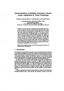
Fig. 4. A two-state Markov chain model for the large-scale fading.
400 ms. This is the worst case delay that a video conferencing application can tolerate [16]. Data will be discarded by the error control module if its delay is over 400 ms. We assume that video is transmitted over a time division multiple access (TDMA) radio network and that the user data rate is 32 Kbit/s. The total number of bits in a packet is 420, consisting of 400 data bits and 20 CRC bits. The data bits may be the original information data or the parity generated by the RS code. An shortened RS code (8, 4, 2) with four bits/symbol is chosen in the hybrid ARQ scheme since this RS code as code is very easy to decode. The ARQ time out is equal to the round-trip delay and the one-way channel delay is a half of the round-trip delay. In this paper, both small-scale fading and large-scale fading are considered. For the small-scale fading, a fading simulator based on Jack’s model is used to generate the Rayleigh fading signal [17]. Large-scale fading strongly depends on the terrain. It is often based on measurements. For simplicity, we use a two-state Markov model for the large-scale fading [18]. In the good state, the local mean signal-to-noise ratio (SNR) of Rayleigh fading (SNR is high. In the bad state the local mean SNR of Rayleigh fading (SNR is low because the mobile moves behind an object. The state transitions are shown in Fig. 4 and are summarized by the transition probability matrix (12) The average SNR generated by the Markov model is (13) Large-scale fading varies very slowly, and it is assumed that the state transitions occur only at the end of a frame interval. The average channel error burst length, which is defined as the average number of frame intervals that the channel is in the bad state, can be obtained by (14) Large-scale fading results in a change in the local mean value of the Rayleigh fading by as much as 10 dB [1]. In the simulation, we assume that the local mean SNR is 30 dB for the good state, and the local mean SNR is 20 dB for the bad state. The QCIF “Mother and Daughter” video sequence is considered, which contains typical video conference-like images, and the video frame interval is about 67 ms (15 frame/s).
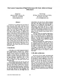
Fig. 5. Intrastream synchronization RMSE versus window size for different average channel error burst length b.
The window size is expected to impact the performance of the synchronization scheme and the tradeoff between synchronization and end-to-end delay. Wireless transmission strongly depends on the channel conditions, such as the channel error burst length, the mobile speed, and the average channel SNR. We will look into the impact of these factors on the resultant performance. In all of our simulations, the resultant frame error rate after error control is less than 10 . The picture quality degradation due to transmission errors is negligible because the large delay bound (400 ms) in the hybrid ARQ error control module allows sufficient retransmissions to correct the errors. This shows that it is beneficial to use a large delay bound in the error control module. . First we investigate the impact of the window size The threshold RMSE of the video intrastream synchronization is set to be 5 ms. Experiments have shown that the human perception system will not notice a skew less than 80 ms between video and audio [15]. The maximum allowed interstream synchronization error (skew) between the video and audio streams is therefore set to be 80 ms. The smoothing recovery parameter in the playout time determination algorithm is set to be 1/60 s based on the fact that the frame can be refreshed every 1/60 s with current common display technology. The average end-to-end delay, the RMSE of video intrastream synchronization, and the RMSE of video and voice interstream synchronization are used as the performance metrics. Note that their values are measured in terms of the source clock; that is, the source clock is used as the common reference to measure the resultant end-to-end delay and synchronization performance. Fig. 5 shows the intrastream synchronization RMSE versus the window size for several different values of average channel error burst length. The corresponding interstream RMSE and the end-to-end delay are showed in Figs. 6 and 7, respectively. The mobile speed is 2 km/h, and the average channel SNR is 26 dB. We noticed that when the window size is very small, the RMSE value is very large. The reason is that if a
LIU AND EL ZARKI: DELAY AND SYNCHRONIZATION CONTROL MIDDLEWARE
1669
Fig. 6. Interstream synchronization RMSE versus window size for different average channel error burst length b.
Fig. 7. End-to-end delay versus window size for different average channel error burst length b.
very small window size is used, the clock adjustment scheme becomes too sensitive. A short-term communication delay variation due to Rayleigh fading results in a clock adjustment so that the long-term communication delay characteristics cannot be caught accurately. Moreover, the frequent clock adjustment itself introduces many synchronization errors. A large window size is necessary to catch the relative long-term communication delay characteristics accurately. Only when the communication delay characteristics change dramatically is the clock adjusted so that a good tradeoff between synchronization and end-to-end delay is obtained. On the other hand, if the window size is too large, the reaction of the scheme to the changes in the communication delay characteristics will be slow. The average end-to-end delay increases with increase in the window size as shown in Fig. 7 because it takes a longer time to adjust the end-to-end delay down whenever the channel conditions become good. We have observed that when the source rate control is used, the impact of Rayleigh fading on the communication delay variation lasts several frames (several hundreds milliseconds) even if the mobile is very slow, such as at a speed of 2 km/h. With a window size of several hundreds of frames, the impact of short-term communication delay variation can be smoothed out. We also notice that both the synchronization RMSE and the mean end-to-end delay become larger when the average error burst length of the large-scale fading is smaller. Smaller average error burst length implies that the communication delay characteristics change more often so it is more difficult to catch the communication delay characteristics. To get some insight, we show the typical operation of the synchronization scheme in Fig. 8. The window size is set to be 450 frames. We observe that the scheme tries to keep the end-to-end delay low to obtain good interactivity when the channel is good and the communication delay jitter is small. When the channel becomes poor, the scheme increases the equalization delay to compensate for the large communication delay jitter introduced by retransmissions. The
end-to-end delay is scarified to preserve good synchronization performance. Next, we study the impact of the channel conditions on the performance. The window size is set to be 450 frames and the threshold intrastream synchronization RMSE to be 5 ms. Fig. 9 presents the resultant intrastream synchronization RMSE versus the average channel SNR for a slow mobile km/h) and a fast mobile (speed km/h). (speed The corresponding interstream synchronization RMSE and the mean end-to-end delay are shown in Figs. 10 and 11, respectively. The curves for the uncontrolled case are also shown in the figures for comparison. Uncontrolled means that a video frame is displayed as soon as it is received; that is, the end-to-end delay is equal to the communication delay. Audio is played with the mean communication delay of the video for the uncontrolled case. We observe that without the synchronization control, the synchronization RMSE is quite high due to the communication delay jitter. When the average channel SNR is higher, the channel is in a good state most of time, and the communication delay jitter becomes smaller due to rarer retransmissions. Thus, the synchronization RMSE decreases. When the mobile speed is high, the error pattern is more random so that a smaller synchronization RMSE is obtained due to less communication delay jitter. We assume that the audio always arrives on time and is played out with the mean communication delay of the video stream for the uncontrolled case. The communication delay jitter of the video stream determines the characteristics of both intrastream and interstream synchronization. There is no significant change in the mean end-to-end delay for the uncontrolled case when the average channel SNR and the mobile speed change. When synchronization control is used, the synchronization RMSE is kept low (the resultant RMSE of intrastream synchronization is less than the threshold RMSE 5 ms). However, the mean end-to-end delay is increased compared to the uncontrolled case. This is because a controlled equalization delay is introduced to compensate for the communication delay
1670
IEEE JOURNAL ON SELECTED AREAS IN COMMUNICATIONS, VOL. 17, NO. 9, SEPTEMBER 1999
Fig. 8. The communication delay and the end-to-end delay determined by the clock adjustment algorithm.
Fig. 9. Intrastream synchronization RMSE versus average channel SNR for a slow mobile (speed = 2 km/h) and a fast mobile (speed = 100 km/h).
Fig. 10. Interstream synchronization RMSE versus average channel SNR for a slow mobile (speed = 2 km/h) and a fast mobile (speed = 100 km/h).
jitter. When the average SNR and/or the mobile speed is high, the communication delay jitter decreases, and less equalization delay is required to compensate for the communication delay jitter so that the resultant end-to-end delay can be lower. This shows that the adaptive synchronization scheme performs reasonably well, as it can effectively adjust the equalization delay to satisfy the synchronization requirements and keep the end-to-end delay low based on the channel conditions. Finally, we look into the tradeoff between the synchronization and the end-to-end delay. By dimensioning the threshold and the window size , the tradeoff between RMSE the synchronization and the end-to-end delay can be controlled. is made small, the resultant RMSE For example, if
is small, which in turn results in a large mean end-to-end becomes very small, the clock is adjusted delay. If frequently, and the resultant synchronization RMSE becomes larger, but the mean end-to-end delay is smaller. Fig. 12 shows the resultant RMSE of the intrastream synchronization versus the mean end-to-end delay for two different values of average channel SNR: 26 and 30 dB. The mobile speed is 2 km/h, and the average error burst length of the large-scale fading is 4500 frames. As expected, we observe that the end-to-end delay increases with the decrease in the synchronization RMSE. It is also noticed that given certain synchronization requirements, high channel SNR results in much smaller end-to-end delay. This shows again that an adaptive synchronization
LIU AND EL ZARKI: DELAY AND SYNCHRONIZATION CONTROL MIDDLEWARE
Fig. 11. End-to-end delay versus average channel SNR for a slow mobile (speed = 2 km/h) and a fast mobile (speed = 100 km/h).
1671
to dynamically adjust the source rate based on the channel conditions so that available channel bandwidth is efficiently utilized. The original temporal relationship of the real-time information streams is distorted due to delay jitter introduced by retransmissions, which causes synchronization problems in multimedia services. We studied the approach of employing a large delay bound for the hybrid ARQ error control module of the communication system to effectively correct transmission errors and an adaptive synchronization scheme on top of it to maintain synchronization and to keep end-to-end delays low. A synchronization scheme was also presented that adaptively changes the end-to-end delay to match the long-term communication delay variation due to large scale fading and smoothly recovers from the synchronization errors. The performance of the proposed communication system was evaluated under different channel conditions. Both large-scale (shadowing) fading and small-scale (Rayleigh) fading were considered. It was shown that the proposed mechanisms are able to adapt to different channel conditions and provide good QoS support for multimedia services over wireless PCS networks. REFERENCES
Fig. 12. Mean end-to-end delay versus intrastream synchronization RMSE for different average channel SNR.
scheme is desirable. It can achieve a desirable tradeoff between synchronization and end-to-end delay. If a fixed end-to-end delay is set based on the worst case, for example 400 ms, it will result in very large unnecessary end-to-end delays when the channel is good, which impairs the interactivity of the real-time service, i.e., degrades the QoS. VII. CONCLUSIONS In this paper, we have demonstrated that error control, source rate control, and synchronization control must be jointly considered in the design of a service-enabling platform to support efficient and reliable multimedia services over wireless PCS networks. The hybrid ARQ scheme adapts to the varying channel conditions by retransmitting erroneous packets. It can significantly improve transmission reliability and yield high throughput for nonstationary wireless channels. However, it results in variable effective data rates for current PCS networks and large delay jitter. An ASRC mechanism can be used
[1] J. Padgett, C. Gunther, and T. Hattori, “Overview of wireless personal communications,” IEEE Commun. Mag., vol. 33, pp. 28–41, Jan. 1995. [2] B. Sklar, “Rayleigh fading channels in mobile digital communication systems,” IEEE Commun. Mag., vol. 35, pp. 90–109, July 1997. [3] H. Liu and M. El Zarki, “Performance of video transport over wireless networks using hybrid ARQ,” in Proc. ICUPC’96, Boston, MA, pp. 210–214. [4] M. Khansari, A. Jalali, E. Dubois, and P. Mermelstein, “Low bitrate video transmission over fading channels for wireless microcellular systems,” IEEE Trans. Circ. Syst. Video Technol., vol. 6, pp. 1–11, Feb. 1996. [5] ITU-T Recommendation H.263, “Video coding for low bitrate communication,” 1996. [6] S. Lin and D. Costello, Error Control Coding: Fundamentals and Applications. Englewood Cliffs, NJ: Prentice-Hall, 1983. [7] H. Liu and M. El Zarki, “Adaptive source rate control for real-time wireless video transmission,” ACM/Baltzer Mobile Networks Applicat., vol. 3, no. 1, pp. 49–60, 1998. [8] R. Steinmetz, “Synchronization properties in multimedia communication systems,” IEEE J. Select. Areas Commun., vol. 8, pp. 401–412, Apr. 1990. [9] J. Escobar, D. Deutsch, and C. Partridge, “Flow synchronization protocol,” in Proc. IEEE INFOCOM’92, pp. 1381–1387. [10] L. Lamont, L. Li, R. Brimont, and N. D. Georganas, “Synchronization of multimedia data for a multimedia news-on-demand application,” IEEE J. Select. Areas Commun., vol. 14, pp. 264–278, Jan. 1996. [11] J. Gibbon and T. Little, “The use of network delay estimation for multimedia data retrieval,” IEEE J. Select. Areas Commun., vol. 14, pp. 1376–1387, Sept. 1996. [12] M. Yuang, S. Liang, Y. Chen, and C. Shen, “Dynamic video playout smoothing method for multimedia applications,” in Proc. IEEE INFOCOM’96, pp. 1365–1369. [13] S. Yoo and D. Kim, “An unified synchronization mechanism for general multimedia services in ATM networks,” in Proc. IEEE INFOCOM’97. [14] C. Liu, Y. Xie, M. Lee, and T. Saadawi, “Multipoint multimedia teleconference system with adaptive synchronization,” IEEE J. Select. Areas Commun., vol. 14, pp. 1422–1435, Sept. 1996. [15] R. Steinmetz, “Human perception of jitter and media synchronization,” IEEE J. Select. Areas Commun., vol. 14, pp. 61–72, Jan. 1996. [16] R. Cox and P. Kroon, “Low bitrate speech coders for multimedia communication,” IEEE Commun. Mag., vol. 34, pp. 34–41, Dec. 1996. [17] M. Jeruchim, P. Balaban, and K. Shanmugan, Simulation of Communication Systems. New York: Plenum, 1992. [18] E. N. Gilbert, “Capacity of burst noise channels,” Bell Syst. Tech. J., vol. 39, pp. 1253–1256, 1960. [19] ITU-T Draft Recommendation H.223, “Multiplexing protocol for low bitrate multimedia communication,” Nov. 1996.
1672
IEEE JOURNAL ON SELECTED AREAS IN COMMUNICATIONS, VOL. 17, NO. 9, SEPTEMBER 1999
Hang Liu received the B.S. degree from Tianjin University, China, in 1985, the M.S. degree from the University of New Orleans, New Orleans, LA, in 1992, and the Ph.D. degree in electrical engineering from the University of Pennsylvania, Philadelphia, in 1997. He joined the C&C Research Laboratories, NEC USA, Inc., Princeton, NJ, in 1997, where he is currently involved in the development of a prototype wireless ATM network. His research interests include mobile networks, ATM-based networks, video compression and communications, and multimedia services over wired and wireless ATM networks.
Magda El Zarki (S’81–M’88) received the B.E.E. degree from Cairo University, Egypt, in 1979, and the M.S. and Ph.D. degrees in electrical engineering from Columbia University, New York, NY, in 1981 and 1987, respectively. She worked from 1981 to 1983 as a communication network planner in the Department of International Telecommunications at Citibank, New York, NY. She joined Columbia University in 1983 as a Research Assistant in the Computer Communications Research Laboratory, where she was involved in the design and development of an integrated local area network testbed called MAGNET. In 1988, she joined the faculty of the Department of Electrical Engineering at the University of Pennsylvania, Philadelphia, PA, teaching courses and conducting research in the field of telecommunications, where she currently serves as an Associate Professor. She also holds a secondary appointment in the Department of Computer and Information Sciences. In January 1993, she was appointed as a part-time Professor of Telecommunication Networks in the Faculty of Electrical Engineering at Delft University of Technology, Delft, the Netherlands. Dr. El Zarki is a member of the ACM and Sigma Xi. She is actively involved in many of their sponsored conferences and journals. She was the Technical Program Chair of IEEE INFOCOMM’94.