ing and error prone activities, e.g., by generating code di- rectly from detailed ..... generate ADA code running on the PolyORB middleware, and ADA or C code ...
36th Euromicro Conference on Software Engineering and Advanced Applications (SEAA), 2010, Lille, France. Copyright by IEEE.
Deployment Modelling and Synthesis in a Component Model for Distributed Embedded Systems1 Jan Carlson, Juraj Feljan, Jukka M¨aki-Turja and Mikael Sj¨odin M¨alardalen Real-Time Research Centre, M¨alardalen University, V¨aster˚as, Sweden {jan.carlson, juraj.feljan, jukka.maki-turja, mikael.sjodin}@mdh.se Abstract We present an approach to combine model-driven and component-based software engineering of distributed embedded systems. Specifically, we describe how deployment modelling is performed in two steps, and present an incremental synthesis of runnable representations of model entities on various abstraction levels. Our approach allows for flexible reuse opportunities, in that entities at different levels of granularity and abstraction can be reused. It also permits detailed analysis, e.g., with respect to timing, of units smaller than a whole physical node. We present a concept, virtual nodes, which preserves real-time properties across reuse and integration in different contexts.
1 Introduction Development of distributed embedded systems is a complex and difficult task, influenced by factors such as resource limitations, safety concerns, real-time requirements, interplay between software and hardware, etc. The complexity of the functionality realized by software in these systems is also steadily increasing, while at the same time a short time-to-market is required to stay competitive in many embedded system domains. Model-driven engineering (MDE) and component-based software engineering (CBSE) are two emerging approaches to address these and other challenges. MDE advocates the use of models, not only for capturing high-level design ideas and for documentation, but as key artefacts throughout the development process. The goal is to reduce development time and efforts, and increase product quality by raising the level of abstraction and automating some time consuming and error prone activities, e.g., by generating code directly from detailed models instead of implementing it manually [22]. The existence of explicit models at an early stage 1 This work was supported by the Swedish Foundation for Strategic Research via the research centre P ROGRESS .
also permits various types of analysis to be performed in order to quickly identify potential problems in the design. In CBSE, systems are built by assembling components with well-defined boundaries and explicitly specified interfaces and context dependencies [25, 7]. The initial goal was to facilitate software reuse, but other advantages include reduced time-to-market, enhanced quality and simplified maintenance [27]. With the strong encapsulation comes also the possibility to apply modular and compositional techniques for analysis and testing, which helps alleviate system complexity. Most component-based approaches consider components in the form of deployable binary entities, but some, in particular those targeting resource constrained domains, view components as design-time entities, and let the component boundaries dissolve in later stages of the development process in order to make the final system sufficiently efficient. In this paper we present an approach to incremental deployment of model-concepts to runnable entities (i.e. synthesis of runnable entities from model entities). The work is presented within the context of ProCom component technology [5, 6, 23]. Previous work on ProCom has not presented our incremental approach to generating a runnable system or how to test and analyse components on different abstraction levels. ProCom has been designed with the ambition to combine model- and component-based development in order to benefit from their respective advantages (i.e., the early analysis and the automated code synthesis from MDE, and the strong encapsulation facilitating reuse and product line development from CBSE). Two key aspects of this integration can be observed in ProCom. First, for the early development phases we propose a model-based design methodology centred around a notion of architectural design-time components. Aspects such as functional behaviour, timing and resource usage are all modelled for individual components in isolation, which facilitates reuse of models and analysis results. When components are composed to form larger units, so are these models, resulting in models of the overall sys-
tem behaviour. The second aspect of the integration concerns the later phases of development, and is of greater significance to this paper. Rather than a single synthesis step where the entire system is generated, the synthesis is preformed in smaller steps where individual parts of the final system, e.g., runtime components, are created in isolation. ProCom exploits both the reuse and encapsulation benefits of CBSE, and the potential of MDE for early analysis and automated generation of low-level artefacts. Moreover, combining the two approaches results in the following additional benefits: Flexible reuse. Reuse of design-time components including behavioural models, implementation and early analysis and validation results; as well as concrete runtime entities with predictable temporal behaviour also in new contexts, which reduces efforts related to testing, validation and certification. Support for mixed maturity. Early analysis can take advantage of detailed analysis results (e.g., static code analysis including also generated glue code) when such results exist, for example when a part of the system is reused as a runtime component or at a point when some parts have been fully implemented and synthesised while other parts remain high-level models. Reuse and efficiency tradeoff. Performing synthesis on small units in isolation before composing them results in more entities to reuse, while synthesising larger units allows for more optimizations in each step. This paper describes how the relations between designtime components and run-time entities are modelled in ProCom, and outlines the synthesis process where the different run-time entities are created. In particular, it introduces the notion of virtual nodes, an intermediate level in the allocation of functional units to the physical nodes of the system, that provides encapsulation of behaviour with respect to timing and resource usage, and introduces another type of reusable unit in addition to the design-time components. The remainder of the paper is organised as follows. Section 2 describes some important characteristics of the embedded systems domain, and Section 3 surveys related work. Section 4 outlines the overall approach, which is then detailed in Sections 5 and 6, before Section 7 concludes the paper.
2 Embedded Systems An embedded system is a computer system, and its associated software, built into some piece of equipment. The vast majority of CPUs manufactured yearly (more than
99%) are used for embedded systems [12]. Also, a significant portion of the global software development effort is put into developing and maintaining embedded systems. This paper primarily targets embedded control systems. Such systems are used to control the equipment they are built into. Often this control is exercised under stringent real-time and safety requirements. Examples of equipment which, today, are software controlled include airplanes, trains, cars, media-equipment, and industrial robots. Conditions for development of embedded control systems differ significantly from development of desktop- and Internet-software. We have previously investigated the key requirements on component technologies for vehicular control systems [19] and some of the requirements addressed in this paper are: Maintainable and extendable. Many systems live for many years (several decades) and need continuous updates, e.g., in conjunction with upgrades of mechanical and electrical parts of the systems. Reusable. Many companies sustain a product line architecture with large amounts of reuse between different products within a product family. Testable and debuggable. Embedded systems are notoriously difficult to test and debug. Reasons for this include limited observability of the real-time evolution of internal state, and difficulties in reproducing execution-scenarios. Resource constrained. The component technology and the systems constructed using it should make efficient use of computational resources (e.g. CPU, RAM and flash). The reason for this is not only to keep hardware cost to a minimum, but also e.g. to conserve energy during run-time and to avoid upgrading hardware when adding new functionality to an existing product. Analyzable. Key extra-functional properties, such as execution delays and memory consumption, should be predictable by analyzing the assembly of components. Analysis is desired to avoid building systems with unfeasible timing behaviour or which deplete resources (such as RAM) at run-time. Statically configured. Partly a consequence of the requirements above, partly to fit with existing development and testing processes, and partly to comply with safety standards (see below) it is desirable to make static (i.e. pre-product shipping) configuration of software and bindings between software components. Benefits of static configuration include predictable boot behavior, lower overhead, and increased determinism during testing.
The ongoing introduction of safety certification according to standards such as IEC 61508 [15] and ISO/DIS 26262 [16] also place increased burden on developers to argue correctness of systems. To this end mathematical analysis is a favoured method to guarantee certain behaviours (or absence thereof). In lack of mathematical (or other) proof, developers resort to testing, which is time consuming and expensive; especially if the whole system has to be completely retested for each minor modification. The approach proposed in this paper addresses all of the above requirements. Maintenance, extensibility, testing and reuse is supported by encapsulating run-time artefacts into reusable entities which can be reused without renewed testing of the entity. Analyzability of models is provided by the ProCom component technology, and the encapsulation of run-time entities allows reuse of the analysis results for those entities during maintenance and upgrades. The resource efficiency and static configuration comes with the ProCom component technology which has been specifically designed to produce highly optimized, pre-configured systems.
3 Related Work We present related work from the perspective of the relation between functional/logical architecture elements and elements in the final executable system. In line with ProCom combining MDE and CBSE, we categorize the surveyed technologies into two groups, namely component models for embedded systems, and model-driven approaches.
3.1
Component models for embedded systems
CBSE has been successful mainly in domains such as desktop- and enterprise applications, but recently many component based approaches targeting embedded systems have been developed both in academia and in industry. Many of them are restricted to development of single node systems, but some explicitly target distributed systems. Here, we survey Rubus and Koala from the former category, and AUTOSAR and COMDES-II from the latter. Rubus [13] is a component model for dependable embedded real-time systems, developed in cooperation between Arcticus Systems and M¨alardalen University. The Rubus tool chain covers three key activities in real-time development — design, analysis and synthesis. Rubus systems are modelled using a graphical design tool, and different analysis techniques are provided in the form of plug-ins. Finally, the run-time infrastructure is generated for the desired runtime platform. Rubus does not assume a particular platform, as long as it preserves the semantics defined by the Rubus
component model. However, the current tool chain synthesis results in a task set that can be executed in the Rubus real-time operating system. Work on extending Rubus to handle distribution is currently under way. Koala [26] is a component model and architectural description language targeting consumer electronics, developed by Philips. It aims to achieve a strict separation between component- and system development, i.e., component builders make no assumptions of the systems in which the components are going to be used. From the model of a system defined using the Koala architectural language, the Koala compiler reads component- and interface definitions, and generates header- and C code files. Koala does not imply a particular deployment platform. Rather, there is a set of makefiles that control how executables are built for particular platforms. COMDES-II [17] is a component-based software framework intended for efficient development of distributed embedded control systems with hard real-time requirements. The architectural model of COMDES-II consists of two layers. At the system level, applications are modelled in terms of actors that exchange asynchronous signals. Actors may be logically combined into subsystems, which are then allocated to network nodes. The functionality is defined inside actors, in terms of function blocks. There is an apparent similarity between COMDES-II and ProCom regarding the two architectural levels, but COMDES-II lacks an intermediate deployment level that ProCom has in terms of virtual nodes. Deployment is handled by a tool that parses COMDES-II models defined in XML and automatically generates C source code. AUTOSAR [1] is an initiative of a number of automotive manufacturers and suppliers to handle the growing complexity of developing vehicular embedded systems by defining a standardized architecture. The functional software in AUTOSAR is defined in terms of software components. According to the AUTOSAR methodology, in the first phase of the deployment, components are mapped to particular Electronic Control Units (ECUs), taking in account the system constraints (extra-functional properties). Then, each ECU is configured separately, based on the deployment of components to the ECU. Finally, an executable is generated for each ECU. A tool suite supporting the complete AUTOSAR methodology is still missing.
3.2
Model-driven approaches
Here we survey two model-driven technologies: AADL and OMG’s Deployment and Configuration. The Architecture Analysis and Design Language (AADL) [11] is an architecture description language for design and analysis of embedded real-time systems, standardized by SAE International. It comprises software abstrac-
tions in terms of software components (e.g., thread, data, process, subprogram), and hardware abstractions in terms of execution platform components (e.g., processor, memory, bus, device). The main purpose of AADL is to enable verification of extra-functional system properties, by performing analysis on an AADL model of the system. However, AADL can be used to aid the whole development process — design, analysis and deployment. At T´el´ecom Paris, this is achieved by employing their Ocarina tool suite [14]. The development process with Ocarina is the following. First, the application designer builds an AADL application model and maps the application model to an AADL execution platform model. This mapping is then assessed (semantic analysis, schedulability analysis and behavioral analysis), before code is generated from the mapping. Finally, middleware is selected and compiled together with the generated code and user code that implements AADL components from the application model. Currently, Ocarina can generate ADA code running on the PolyORB middleware, and ADA or C code running on the PolyORB-HI middleware. The Deployment and Configuration specification [20] defines mechanisms to facilitate the deployment of component-based applications onto target systems. The specification is standardized by Object Management Group. It is compliant with model driven architecture and defines a platform independent model (PIM) with three levels that describe component-based applications, heterogeneous distributed target platforms, and mappings of an application to a target, respectively; a deployment process, based on a set of actors which manipulate the models; a UML profile providing a concrete syntax for the abstract syntax defined by the PIM; and a platform specific model (PSM), specified for the CORBA Component Model. The Deployment and Configuration specification is generic. However, an open-source implementation specifically targeting distributed real-time embedded system exists [9].
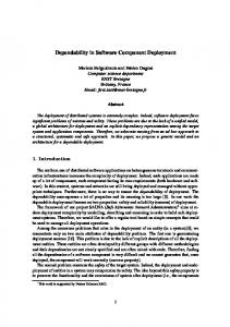
4 Overview Figure 1 depicts the main formalisms and artefacts, from the perspective of this paper, of the ProCom development process. We partition the concerns related to deployment into deployment modelling, addressing how to capture and represent deployment related design decisions, e.g., how functionality is distributed over the nodes of the system; and synthesis, the process of generating concrete runnable representations of different modelling elements. In addition to these, the full process also contains activities related to for example behavior modelling, early analysis, testing, etc., that fall outside the scope of this paper (see [18]). As shown in the figure, modelling is supported by four
Figure 1. Overview of deployment modelling formalisms and synthesis artefacts.
distinct but related formalisms. ProSave and ProSys are used to model the functional architecture of the system under construction, addressing the different concerns that exist on different levels of granularity in distributed embedded systems. In short, ProSys models a system as a collection of active, concurrent subsystems communicating via asynchronous message passing, and ProSave addresses the detailed structure of an individual subsystem, by specifying how data and control are transferred between passive components. Both ProSys and ProSave allow composite components, i.e., components that are internally realized by a collection of interconnected subcomponents. For details on ProSave and ProSys, including the motivation for separating the two, see [5, 6, 23]. The overall purpose of the deployment modelling activities is to capture how functionality, in the form of ProSys subsystems, is divided between the nodes of the system. This is performed in two steps, introducing an intermediate level where ProSys subsystems are allocated to virtual nodes that, in turn, are allocated to physical nodes. This approach allows more detailed analysis to be performed without full knowledge of other parts that will share the same physical node in the final system. A realisation based on hierarchical scheduling and resource budgets ensures that a virtual node can be analysed independently from the rest of the system, also with respect to timing. Section 5 describes this further. Note that the modelling activities are seen as independent and potentially overlapping, rather than being performed in a particular order. Allocation decisions can be deferred until a full specification of the functional architecture exists, or modelling the physical platform and identifying virtual nodes can be done before functionality is elaborated. In many cases, some parts of the system will be defined in detail at an early stage, for example subsystems reused from previous projects, while other parts are elaborated and implemented at a later stage. The synthesis activities, on the other hand, are performed in a fixed order since each step requires the results from the
Figure 2. The main deployment modelling concepts and relations. previous step as input. Still, this does not mean that the entire system must move to the next phase at the same time. For example, as soon as runnables have been created for all ProSys subsystems allocated to a virtual node, that node can be synthesised regardless of the status of other parts.
5 Deployment modelling As discussed in the previous section, deployment decisions are captured in two steps where subsystems are allocated to virtual nodes that, in turn, are allocated to the physical nodes of the system. Figure 2 depicts the key modelling elements supporting this idea, and how they are related. The rest of this section provides more detailed information about the different parts, illustrated by a running example. Example: As our example, we consider the turntable drilling system described by, e.g., Bos and Kleijn [4]. The system consists of a rotating table that moves products between processing stations where they are drilled and tested. Products are placed on the table by a load station (not modelled as part of the system) after which they are moved to the drill station by rotating the turntable 90◦ . Drilling requires that the product is securely held in place by a clamp mechanism. After drilling, the product is moved to a test station where the depth of the drilled hole is measured. Finally, the unload station removes the product from the table, provided that it passed the test. If not, it remains on the table to be drilled and tested again. The turntable has four slots, each capable of holding one product, and thus the stations can operate in parallel so that a second product can be drilled while the first is being tested, etc. Figure 3 depicts the ProSys design of the turntable application, consisting of four components (called subsystems in ProSys) and the messages they exchange in order to synchronise their behaviour. The Driller subsystem is composite, and each of the remaining subsystems in the system, including the two in Driller, can be further decomposed into smaller ProSys subsystems or into entities in ProSave, and
Figure 3. The turntable system modelled in ProSys.
at the bottom of the hierarchy the primitive ProSave components can be given implementations in C.
5.1
Virtual node modelling
As a modelling concept, virtual nodes are not very rich. Interfaces and interconnections, as well as information about dependencies on libraries or physical devices, are derived from the subsystems allocated to them. An important aspect of the virtual nodes, however, are the resource budgets defining a minimum level of resource availability that will be provided to the contents of the virtual node. These budgets introduce an important separation of concerns in the deployment process in that they allow (i) detailed timing analysis of a virtual node in isolation, independent from other functionality residing on the same physical node in the final system; and (ii) the feasibility of a partial allocation to be determined at an early stage, before all functionality has been implemented. The nature of the resource budgets depends on the analysis that should be supported and the type of resources the analysis considers. Since we aim for a system realisation based on hierarchical scheduling [10] and corresponding schedulability analysis techniques, we initially focus on CPU budgets in a form that is appropriate for this approach. For each virtual node, a CPU budget is specified as a pair
�C, T �, with the interpretation that during each time period of length T the virtual node is guaranteed access to the CPU for at least C time units. The access may, however, be distributed arbitrarily over the period, and the distribution can differ from one period to the next. For example, giving a virtual node a budget of �50, 100� or �250, 500� both mean that it is entitled to half of the CPU bandwidth over time, but with the second budget it might have to wait much longer for CPU access in some situations. In order to handle other resources that are shared between virtual nodes, such as access to shared memory or external devices, bounds for access time to each shared resource are also required. For information on how these budgets can be used in the schedulability analysis see [3].
5.2
Allocation of subsystems to virtual nodes
This allocation is a straightforward many-to-one mapping from subsystem instances to virtual nodes, but a restriction applies in the case of composites subsystems: If two subsystem instances are related by means of composition (directly or indirectly through multiple levels of nesting), at most one of them can be allocated. Instead, all constituents of an allocated subsystem, on any level of nesting, are said to be implicitly allocated to the same virtual node. The derived interface of a virtual node consists of the ports of all subsystem instances allocated to it. Implicitly allocated subsystems do not contribute to the interface, although their functionality will be part of the virtual node when synthesised. Dependencies, e.g., to physical devices, are also inherited from the allocated subsystems, but in this case the implicitly allocated constituent subsystems also contribute. Example: To illustrate the deployment modelling, we first define four virtual nodes and allocate the subsystems to them as shown in Table 1. Subsystems that we know must end up on different physical nodes, such as Turntable and Tester, should be separated to different virtual nodes. The controller, although not bound to a specific physical node, is put in a separate virtual node to avoid grouping it with other subsystems at this stage. For Driller, Clamp and Drill there are actually three options: We can (i) allocate Clamp and Drill to different virtual nodes, which would permit more robust reuse; (ii) place them in the same node, which increases efficiency and allows for higher precision in the analysis of their interaction; or (iii) allocate the composite subsystem Driller, which also enforces the encapsulation so that for example the ports of the Drill subsystem remain non-accessible also if the virtual node is reused.
Table 1. Virtual nodes and allocation of subsystems. Virtual node VN1 VN2 VN3 VN4
CPU budget �125, 500� �60, 100� �80, 100� �60, 100�
Subsystem allocation Controller Turntable Clamp, Drill Tester
With the allocation specified in Table 1, the interface of consists of three input- and three output ports. If, instead, the composite Driller subsystem was allocated, the interface would have one input- and one output port. The budgets should be based on system requirements and early resource usage estimates, since they influence the responsiveness of the virtual node. In the turntable system, the controller is the least time critical part, and also less computationally demanding, which is why it is given a smaller budget with a fairly long period.
VN3
5.3
Physical node modelling
This part of the deployment model defines the hardware nodes of the system and how they are interconnected, capturing all properties of the nodes and networks that are required by synthesis or analysis, including processor type, available memory, network type, throughput, etc. The details of this modelling formalism are currently being investigated, and it is possible that parts of some existing approach will be used (e.g., a subset of AADL [11] or SysML [21]) rather that developing a new formalism. For the purpose of this paper, we use a simple physical node model consisting of physical nodes connected by networks.
5.4
Allocation of virtual nodes to physical nodes
Similarly to the allocation between subsystems and virtual nodes, this is represented by a many-to-one mapping. In addition, dependencies refering to abstract devices in the virtual nodes should be associated with concrete devices of the physical nodes. Although not covered in Figure 2, the allocation model should also map the interconnections between virtual nodes to physical network connections. Depending on the network type, additional specification might be needed. For example, in the case of a controller area network (CAN bus) connection, priorities have to be assigned.
Example:
6.2
For the allocation to physical nodes, we assume a physical execution platform consisting of three identical nodes connected to a common bus. The tree nodes are located close to the turntable motor, the drill station and the test station, respectively. Thus, the allocation of virtual nodes VN2, VN3 and VN4 is straightforward, while VN1 can be placed more freely. However, allocating it to the same node as VN3 would result in a CPU overutilisation (105%) and is thus not permitted. Figure 4 shows one of the possible allocations.
ProSys subsystems interact with each other using asynchronous message channels. Subsystems can also react to internal stimuli from timers and interrupts. A composite ProSys subsystem contains one or more interconnected ProSys subsystems, while a primitive ProSys subsystem typically is made up of a set of ProSave components (see section 6.5 for other alternatives).
Figure 4. Allocation of virtual nodes to physical nodes.
6 Runnable Representations In this section we describe the different artefacts that constitute runnable representations of ProCom model entities and how these artefacts can be synthesised using information from the models, and previously synthesised runnables. We also show which properties can be established for each type of artefact by means of analysis and testing.
6.1
ProSys
The runnable representation of a ProSys subsystem is a set of tasks and parameters that reflect their execution requirements and include information such as period, offset, and deadline. Note however that it is not possible to verify these requirements in this step, since interference from other ProSys subsystems cannot be accounted for. When synthesising a ProSys subsystem from a set of ProSave components, the main task is to identify how many tasks are needed and which ProSave components should be executed in which task. Within a synthesised ProSys subsystem all communication is statically resolved and not visible outside of the subsystem. It is the responsibility of the synthesis tool to ensure data-port integrity by, e.g., inserting mutex-code before accessing port data, or by scheduling the execution in such a way that integrity is guaranteed. The only visible communication is that with the ProSys subsystem’s message ports (which need to be protected by mutexes, since it is not known how these ports will be accessed by the environment).
6.3
Virtual Node
ProSave
A primitive component has one function for each service it provides. When a service is activated, the corresponding function is called with the values on the input ports. When the function returns, the service is completed and returned values are made available to any components that are connected to the output ports of the service [5]. Composite ProSave components can be automatically synthesised from their constituents. Conceptually, this synthesis is straightforward; generating the necessary storage areas for port-data, setting up pointers to those areas to be passed to the service-functions, and resolving the order in which to execute services. However, producing a resourceefficient implementation requires several steps of optimisation (e.g. detecting the optimal order to execute services, identifying port-data that can be stored on the stack and those that need to be statically allocated). Regardless of the amount of effort put into this synthesis step, the result is the same simple representation: one C-function for each service of the component.
Contrary to the model-concept of a virtual node, the runtime representation of a virtual node is a rather strong concept. A virtual node represents the functionality of a ProSys subsystem combined with allocated execution resources2. The runnable representation of a virtual node includes a set of tasks, a resource allocation and a real-time scheduler to be executed within a server in a hierarchical scheduling framework [10]. The server will execute with a guaranteed temporal behaviour, using its allocated CPU bandwidth, regardless of any other execution on the physical node. Thus, once a server has been configured for the virtual node, its real-time properties will be preserved when the virtual node is integrated with other virtual nodes on a physical node. We do not prescribe what type of scheduler a virtual node should use; it can be any type of scheduler that provides real-time guarantees. 2 Currently, we focus mainly on CPU-bandwidth and memory. However, in future work other resources, such as energy, could be added.
6.4
Physical Node
The runnable representation of a physical node is the final compiled binary that can be downloaded and executed on the target. The binary contains a set of virtual nodes, a real-time scheduler, and an implementation of the asynchronous message channels used to send ProSys messages between virtual nodes. The scheduler is the top level scheduler in the hierarchical scheduling framework, and is responsible for dispatching the servers of each virtual node according to their bandwidth reservation. The synthesis of a physical node is conceptually straightforward and consists of generating code for inter- and intratask communication, and finally compiling and linking the constituents of the node. However, there is also room for a final optimization step where the parameters of the servers may be tweaked to achieve maximum resource utilization [2].
6.5
Legacy Support
In order to gain industrial acceptance, a component technology needs to enable integration of legacy functionality. Our approach enables legacy functions to be integrated at any of the aforementioned abstraction levels. The separation of model-concepts and runnable representation enable virtually any legacy function to be integrated in a new system. The appropriate level to integrate a legacy function is dictated by its runnable representation. The integrator should choose to introduce the legacy function at the level with the closest match between the legacy function a ProCom runnable representation. That is, if the legacy function is a simple procedure with run-to-completion semantics it should be introduced as a ProSave component, and if it is a set of tasks it should be introduced as either a ProSys subsystem or a virtual node. The choice between ProSys or virtual node depends on the real-time requirements of the legacy function and how it is expected to interact with other functions in the system (a relatively independent function, or a function with tight real-time requirements, could favour to be introduced as a virtual node). One strong aspect of our approach is the possibility to reuse a complete legacy node encapsulated in a virtual node. Since the top level scheduler does not care about the internal scheduling of a virtual node a legacy node can have any operating system and scheduling policy. Thus, if we want to reuse a legacy node on a new and more powerful platform, where it can coexist with other virtual nodes, we only need to make sure that it is allocated to a virtual node with resource budgets that match the original legacy platform.
6.6
Analysis, Testing and Validation
Our approach allows different types of analysis, testing and validation on different levels. The analysis results of one level are used as input to the next level. Thus, analysis results for a component can be reused when a component is reused in new context. ProSave components can be unit-tested and their functional mapping of input-data to output-data can be verified. Analysis on ProSave components should include worstcase execution time (WCET) and memory-usage (worstcase stack usage and code-size are possible to determine at this point). ProSys subsystems can be unit-tested and the integration of their contained ProSave components can be verified. Using models of the ProSys environment some runtime properties, such as proper sequencing of signals, can be tested. However, the detailed timing of signals cannot be verified at this point. Since the ProSys subsystem encapsulates internal communication between ProSave components it is possible to determine the memory need for communication buffers for such internal communication for each ProSys subsystem. Also, since the sequencing of ProSave components is known at this level, the WCET and maximum stack-usage for each task can be determined. Since the functionality of a virtual node is just the sum of the subsystems allocated to it, no further functional testing is needed at this level. However, at this level we can determine the real-time behaviour of the virtual node. Thus, we can now perform real-time analysis and testing of real-time properties. Real-time analysis for a virtual node should use techniques suitable for the real-time scheduler chosen for the virtual node and which are suitable for analysing hierarchically scheduled systems; for fixed-priority and deadlinescheduling, techniques such as [8, 24] can be used. Once the physical node is completed, final integration testing is possible. Analysis at this level is quite trivial; both for CPUbandwidth and memory it is a matter of adding allocated resources for each virtual node (and the small overhead of the top-level scheduler and message passing system) and verify that the bandwidth and memory of the physical node are not depleted.
7 Conclusion We have presented an approach to incrementally synthesise runnable representations of model entities on various levels of abstraction and granularity. The purpose of our approach is to combine the bottom-up process of assembling, testing and analysing systems from existing components (CBSE), and the process of gradually refining abstract models into concrete models from which the final system can be synthesised (MDE).
The approach proposed in this paper addresses key requirements on a technology and process for industrial development of embedded systems. Maintenance, extendibility, testing and reuse is supported by encapsulating run-time artefacts into reusable entities which can be reused without renewed testing of the entity. Analyzability of models is provided by the ProCom component technology, and the encapsulation of run-time entities allows reuse of the analysis results for those entities during maintenance and upgrades. The notion of virtual nodes introduces an intermediate level between functional units and the physical nodes of the system, with entities for which real-time properties are preserved across reuse and integration in different contexts. We have implemented the analysis and run-time techniques used in this paper, and the synthesis tool-chain is under development (currently synthesis of ProSave components and ProSys subsystems exists at prototype stage). Our ongoing work is to complete the synthesis tool-chain and integrate it with the analysis techniques in the ProCom Integrated Development Environment (P RIDE)3 .
References [1] AUTOSAR. http://www.autosar.org/, accessed March 2010. [2] M. Behnam, T. Nolte, M. Sj¨odin, and I. Shin. Overrun methods and resource holding times for hierarchical scheduling of semi-independent real-time systems. IEEE Trans. on Industrial Informatics, 6(1), 2010. [3] M. Behnam, I. Shin, T. Nolte, and M. Nolin. SIRAP: A synchronization protocol for hierarchical resource sharing in real-time open systems. In Proc. of International Conference on Embedded Software (EMSOFT’07), 2007. [4] V. Bos and J. J. T. Kleijn. Automatic verification of a manufacturing system. Robotics and Computer-Integrated Manufacturing, 17(3):185–198, 2001. [5] T. Bureˇs, J. Carlson, I. Crnkovi´c, S. Sentilles, and A. Vulgarakis. ProCom – the Progress Component Model Reference Manual, version 1.0. Technical Report MDH-MRTC230/2008-1-SE, M¨alardalen University, June 2008. [6] T. Bureˇs, J. Carlson, S. Sentilles, and A. Vulgarakis. A Component Model Family for Vehicular Embedded Systems. In The 3rd International Conference on Software Engineering Advances. IEEE, October 2008. [7] I. Crnkovi´c and M. Larsson. Building Reliable ComponentBased Software Systems. Artech House, Inc., 2002. [8] R. I. Davis and A. Burns. Hierarchical fixed priority preemptive scheduling. In ”Proc. of IEEE Real-Time Systems Symposium”, 2005. [9] G. Deng. Deployment and configuration of componentbased distributed, real-time and embedded systems. PhD thesis, Vanderbilt University, 2007. 3 P RIDE
web page: www.idt.mdh.se/pride
[10] Z. Deng and J. W.-S. Liu. Scheduling real-time applications in an open environment. In ”Proc. of IEEE Real-Time Systems Symposium”, December 1997. [11] P. Feiler, B. Lewis, and S. Vestal. The SAE Architecture Analysis & Design Language (AADL): A Standard for Engineering Performance Critical Systems. In IEEE Conf. on Computer Aided Control Systems Design, 2006. [12] T. R. Halfhill. Embedded Markets Breaks New Ground. Microprocessor Report, (17), January 2000. [13] K. H¨anninen, J. M¨aki-Turja, M. Nolin, M. Lindberg, J. Lundb¨ack, and K.-L. Lundb¨ack. The Rubus Component Model for Resource Constrained Real-Time Systems. In 3rd Int. Symposium on Industrial Embedded Systems, 2008. [14] J. Hugues, B. Zalila, L. Pautet, and F. Kordon. From the prototype to the final embedded system using the Ocarina AADL tool suite. ACM Transactions in Embedded Computing Systems, 7(4):1–25, 2008. [15] IEC 61508 – Functional safety of electrical/electronic/ programmable electronic safety-related systems. [16] ISO/DIS 26262 – Road vehicles - Functional safety. [17] X. Ke, K. Sierszecki, and C. Angelov. COMDES-II: A component-based framework for generative development of distributed real-time control systems. In Proc. of the 13th IEEE International Conference on Embedded and RealTime Computing Systems and Applications (RTCSA’07), pages 199–208. IEEE Computer Society, 2007. [18] R. Land, J. Carlson, S. Larsson, and I. Crnkovi´c. Towards guidelines for a development process for component-based embedded systems. In Proceedings of the International Conference on Computational Science and Its Applications (ICCSA’09), pages 43–58. Springer-Verlag, 2009. [19] A. M¨oller, J. Fr¨oberg, and M. Nolin. Industrial Requirements on Component Technologies for Embedded Systems. In 7th International Symposium on Component-based Software Engineering (CBSE’04). IEEE, 2004. [20] OMG. Deployment and Configuration of Component-based Distributed Applications, v4.0, 2006. [21] OMG. SysML Version 1.1, 2008. [22] B. Selic. Model-driven development: Its essence and opportunities. In Proceedings of the Ninth IEEE International Symposium on Object and Component-Oriented Real-Time Distributed Computing (ISORC), pages 313–319. IEEE Computer Society, 2006. [23] S. Sentilles, A. Vulgarakis, T. Bureˇs, J. Carlson, and I. Crnkovi´c. A Component Model for Control-Intensive Distributed Embedded Systems. In 11th International Symposium on Component Based Software Engineering, pages 310–317. Springer Berlin, October 2008. [24] I. Shin and I. Lee. Periodic resource model for compositional real-time guarantees. In ”Proc. of IEEE Real-Time Systems Symposium”, 2003. [25] C. Szyperski. Component Software: Beyond ObjectOriented Programming. Addison-Wesley Longman Publishing, 2002. [26] R. van Ommering. Building product populations with software components. In Proceedings of the 24th International Conference on Software Engineering (ICSE ’02), pages 255–265, New York, NY, USA, 2002. ACM. [27] P. Vitharana. Risks and challenges of component-based software development. Commun. ACM, 46(8):67–72, 2003.