2012 American Control Conference Fairmont Queen Elizabeth, Montréal, Canada June 27-June 29, 2012
Design and Implementation of a Large Measurement-range AFM Scanning System Jim-Wei Wu, Yuan-Zhi Peng, Jyun-Jhih Chen, Kuan-Chia Huang, Mei-Yung Chen, and Li-Chen Fu, Fellow, IEEE
Abstract—Atomic force microscopy (AFM) opens a new window to the nano-world. It is a widely used tool in nano measurement techniques. However, a traditional AFM system suffers from the limitation of small scanning range, due to the short traveling range of piezoelectric positioners. In this paper, we propose a large measurement- range AFM scanning system which combines both fine positioners of piezoelectric and electromagnetic actuators. While the piezoelectric actuation positioner (PAP) provides high speed scanning with nanometer resolution in the z-axis, the precision electromagnetic positioner (PEP) is capable of 1 mm²large field positioning with 20 nm rms error in the xy axes. The overall design of the stage consists of 4 pairs of electromagnetic actuators, monolithic serial flexure guidance with compression springs, an eddy current damper, and a commercial z-axis PAP. Given that there are 1 DOF in PAP and 2 DOF in PEP, the scanning positioners can achieve a large field image scanning. Besides, a stationary compact disk/digital versatile disk pick-up-head (CD/DVD PUH) is used to measure the amplitude of the probe. Moreover, an adaptive sliding mode controller based on the analytical modeling is used to overcome the unmodeled system uncertainties, coupling motion and external noises, including the scanning disturbances. Finally, extensive experiments are conducted, demonstrating feasibility of the proposed system. Index Terms—Nano control, electromagnetic actuation positioner, piezoelectric actuation positioner, CD/DVD PUH, adaptive sliding mode control, AFM
I. INTRODUCTION
S
Canning Probe Microscope (SPM) invented in 1982 [1] is a great imaging measurement technique. However, SPM is only suitable for samples of conductive surface. In order to overcome the weakness as mentioned above, Atomic force microscope (AFM) was proposed in 1986 [2], namely, utilizing a probe with sharp tip to scan the sample topography. Thereby, the AFM can investigate both conductive and insulating materials on atomics scale, and thus becomes widely used in scientific research and industrial application. However, due to the limitation of the traveling range of the piezoelectric positioned, the traditional AFM system can hardly scan over 100 μm. Jim-Wei Wu, Yuan-Zhi Peng, Jyun-Jhih Chen, and Kuan-Chia Huang, are with the Department of Electrical Engineering, National Taiwan University, Taipei, Taiwan, ROC. (E-mail:
[email protected]) Li-Chen Fu is with the Department of Electrical Engineering and Department of Computer Science and Information Engineering, National Taiwan University, Taipei, Taiwan, ROC. (E-mail:
[email protected]) . This work was supported by National Science of Council under the grant NSC 100-2221-E-002-082-MY3 978-1-4577-1096-4/12/$26.00 ©2012 AACC
895
In practice, biological samples, like ribosomes (11 nm) and microtubules (25 nm), can be as small as tens nanometers, but those like the ovum of human beings (100 μm) and the amoeba (800 μm) can also be as large as hundreds of micrometers. Therefore, a large scanning range AFM system will contribute a lot to many research fields Nowadays, many researches of the world focus on this topic. In year 2007, Sinno in France proposed a homemade sample-holder for the purpose of positioning, which has a millimeter traveling range in xy dimensions [3]. This sample holder was realized in year 2009 [4], which has applied a coarse to fine displacement positioner. In year 2009, Eves in Canada proposed the design of a large measurement-volume AFM system whose scanning volume is about 40 mm×40 mm×6 mm, and the design of the positioner was accomplished also with similar coarse and fine positioning [5]. In year 2010, Werner in Netherland introduced a concept of a metrological AFM, which consists of a translation positioner with a motion range of 1x1x1 mm³ [6], but the conceptual positioner has not been physically tested in the AFM scanning experiments. Currently, there are many choices in the long range actuation. The electromagnetic actuation is considered to be a preferable choice since it has both high precision and long travelling range (millimeter level) [7]. Stemming from this fact, several positioners built upon electromagnetic actuation [8][9] have been introduced. Continuing along this stream of thought, later a self-designed precision electromagnetic positioner (PEP) can position the sample in a field of 1 mm² with 20 nm rms error, but its operating frequency is excessively slow, i.e., it cannot exceed 12 Hz [10]. A consequence is that such positioning stage cannot quickly and precisely obtain the scanning image in z direction. Hence, in this research work we employ the piezoelectric positioner, widely used for actuation in AFM instrument, to achieve sample scanning in nanometer resolution. Here, in this paper, we will focus on the design, implementation and control of the integrated AFM system. The featured mechanical design is presented in Section II. In Section III, the analytical model is investigated and its dynamic formulations are derived as basis for subsequent controller design. Furthermore, to overcome the unmodeled
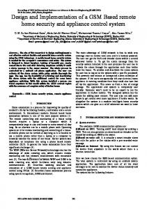
Fig. 1 (a) The moving part- explosion view of the PEP with PAP. (b) The stationary part (c) Schematic drawing of the AFM system
system uncertainties, coupling motion and external noises, including the scanning disturbances, an advanced controller, named adaptive sliding mode controller, is developed for precision positioning in Section IV. The experimental results are presented in Section V, indicating the scanning ability of proposed AFM system.
information, a position cube with a 90 degree gold-coated mirror is screw-locked onto PEP as the scanning unit, reflecting the laser beams emitted from the laser interferometer. A commercial PAP, Piezosystem Jena Tritor 38 T-402, which has the motion range of 38 μm in z axis with high resolution in nm and sub-nm scales, is located at the topmost part. The whole dimensions of PEP are 135×135×70 mm³. The featured parts of PEP and the sensing system will be detailed in the following subsections.
II. MECHANICAL DESIGN The overall exploded view of the AFM system is shown in Fig. 1 (c). The design of the mechanism is mainly divided into the moving part and the stationary part. In application, due to different allocation of the moving part, the design can be further classified as moving sample type and moving probe type AFMs, which have their own suitable applications and advantages. We choose the moving sample type in our design, since it can provide simple optical detector complexity and good scanning quality, and can minimize the Abbe errors given the position where the AFM probe is fixed. Figure 1 (b) depicts a stationary mechanism, which includes a fine tuning linear stage, a CD/DVD PUH, a piezoelectric element (bimorph), a magnetic disk, and a magnetic mount. The fine tuning linear stage is a regulator to adjust the position of the PUH’s laser beam so that it focuses on the cantilever, whereas the CD/DVD PUH is a detection sensor to measure the oscillation amplitude of the cantilever. In addition, the magnetic mount is used to fix the probe, and the piezoelectric element which is employed to oscillate the cantilever of the probe. Figure 1 (a) illustrates the exploded view of PEP, which is the crucial part of this research, together with PAP. The overall structure consists of an adaptor fixing the whole stage onto a vibration-isolation optical table. PEP is composed of a monolithic xy serial compliant flexure plate with two pairs of compression springs, four pairs of electromagnetic actuator, and one eddy current damper. To measure the position
A. Serial Compliant Mechanism In order to realize the large traveling range up to millimeter level, the leaf-spring type flexure beam is hereby adopted. In Fig. 1 (a), the monolithic xy serial compliant mechanism of the flexure beams includes two pairs of leaf springs which are arranged orthogonally and in charge of motions along x-, and y- direction respectively. The designed delicate width of the flexure beams is 0.3 mm. Moreover, a light and stiff material (aluminum alloy 7075) is used, which can improve the bandwidth and the stiffness of the moving stage [11]. As a result, the resulting PEP can reach a working range of 1 mm². Besides, In order to strengthen the decoupled structure and stiffness, and to compensate partial loading in the vertical direction, two pairs of compression springs made of Al 7075 are implemented along the xy axes, as shown in Fig. 1 (a). B. Electromagnetic Actuation In PEP, four sets of VCM are employed as its electromagnetic actuators. Every pair of VCMs provide the actuation in one axis, and for the purpose of avoiding the buildup of heat and disturbance to the coil wires, all coils are attached on the stationary copper layer whereas the permanent magnets are mounted on the moving xy-platen with PM holders, as shown in Fig. 1 (a).
896
C. Eddy Current Damper Since flexure mechanisms bring about a small damping ratio, a contactless Eddy current damper is designed and used as the passive vibration suppression. That is, when a non-ferromagnetic conductor moves in a magnetic field, as illustrated in Fig. 2, or a moving and varying magnetic field intersects a non-ferromagnetic conductor, the relative motion induces a current loop, so-called Eddy current, within the conductor. Hence, the generated force can resist the relative motion between the magnetic field and the conductor. This mechanism is compactly designed as the copper plate in Fig. 1 (a), which then produces a very precise damping force without mechanical wear.
Unlike other traditional AFM sensor, we adopt a commercial CD/DVD PUH (as shown in Fig. 4) to sense the oscillation amplitude of the probe. It has sufficient sensitivity for the application of tapping mode AFM and is a compact and cost-effective sensing sensor. Besides, the laser spot of the CD/DVD PUH is smaller than the width of the AFM’s cantilever, so that the laser energy will not be leaked to the reflective sample to cause sensing errors [12]. III. MODELING AND FORMULATION In order to design a controller with sound performance, the relative properties of specific components in the system should be analyzed, including the stiffness of the flexure mechanism, the damping force provided by the eddy current damper, and the dynamic motion of the positioner. A. Dynamics Formulation of PEP in xy axes
Fig. 2 The eddy current inside the copper plate
D. The Sensing System A 632 nm He-Ne laser interferometer system featuring nanometer resolution and high sampling rate by Agilent Corporation is employed as the sensor for xy axes measurement for PEP. From the exploded view as shown in Fig. 1 (a), a gold-coated right angle special mirror with ±2 arcmins angle tolerance is fixed at the center of the PEP. The whole laser beam paths designed are as shown in Fig. 3, where x-axis and y-axis share equal length and intensity of the laser beam from one laser head.
Fig. 5 The dynamic modeling of serial structure
In the dynamics analysis, the serial flexure mechanism can be modeled as a spring–mass-damper system. Due to the design of the symmetrical flexure mechanism, we can decouple the dynamics associated with x-axis from those associated with y-axis. Besides, the hysteresis effect and thermal drift are regarded as the disturbances. From Fig. 5, we define x and y as the displacements along x and y axes, respectively, and through the help of Newton’s Law, the system dynamics can be expressed in the following form:
Plane Mirror Interferometer 90° Plane Mirror
(1) where is the mass of outer stage allowing the one-DOF motion being constrained along x-axis only, and is the mass of the inner stage contributing to y-axis motion while moving along x-axis with the outer stage simultaneously. The notations and are the coefficients of elasticity, and are the damping constants, and and are the control forces. We can then rewrite the horizontal actuation and the dynamical equation of the two SISO (Single-input single -output) systems as
Reciever Agilent 5517D Laser Header
50% Beam Splitter
Fig. 3 The laser beam paths
(2) To simplify the representation of the equation of motion, we define a variable vector as and reformulate the dynamical equations as: (3)
Fig. 4 The view of CD/DVD PUH.
where 897
is the inertia term,
is the restoration term,
is
treated as the coupling terms in the coefficient matrices estimated by the adaptive law. To simplify the notations in our subsequent analysis, we define as , as , and as , so that Eq. (9) can be re-expressed as: (10) Now, the problem can be formulated as seeking of a proper design of the control vector such that the error state vector will be driven to zero asymptotically.
the damping term, is force-current factor, and is the control effort, and related parameters can be defined as
(4) Since there inevitably exists coupling effect between xand y-axis dynamics, off-diagonal terms should be uncertain but nonzero, and thus the related parameters become:
A. Adaptive Sliding Mode Controller We now define a sliding surface variable following form:
according to the
(11) where is a designed positive diagonal matrix. From Eq. (11), we can easily find that the sliding surface is a function consisting of the error term and its time derivative. Generally, our main purpose is to drive the sliding surface to zero, which simultaneously drives and to zero as well. If the sliding surface tends to zero within finite time then and also converge to zero exponentially. Consequently, the adaptive sliding mode controller is enforced online estimating system parameters and synthesizing the necessary state feedback while simultaneously tuning the controller gains to satisfy the control objective [13]. However, since the sign switching function may induce undesirable chattering easily, for practical consideration we replace that discontinuous function by continuous “saturation” function at the price of trading the asymptotical stability with ultimate bounded stability so that the tracking errors will fall into a residual set. After carefully deriving the sliding surface dynamics, the modified control law is designed as:
(5) B. Dynamics Formulation of PAP in z-axis In general, a linear second order model can be used to represent the nominal dynamics of PAP in z-axis: (6) where z is the shrinking displacement of the vertical positioner, b is the forcing coefficient of the control input u, and a1, a0 represent the damping and the stiffness of the system, respectively. Note that a1, a0 and b can be well estimated via an off-line identification test. We utilize the above dynamics formulations to achieve the controller design described in the next section. IV. CONTROLLER DESIGN In this research work, the adaptive law and a sliding mode controller are integrated as an advanced control which possesses not only stronger robustness but also self-tuning capability which can enhance the AFM’s scanning performance. First, to design a robust controller for PEP, the model uncertainty, external noise and disturbance should be taken into consideration in the dynamics modeling of PEP. Thus, Eq. (3) is rewritten as:
(12) where , , , and are the estimated values of , , , and , respectively; ; is the high gain used to bound the variable uncertainty and scanning disturbances , namely, ; sat(.) is the saturation function defined as
(7) where additional uncertainties, including constant uncertainty denoted as the model uncertainty, varying uncertainty denoted as the external noise and disturbances, and scanning disturbance denoted as disturbance resulting from scanning are added. Here, we assume that the varying uncertainty is bounded with , and then we define the desired position vector as and the error E between the desired vector and the position X as follows: (8) Substituting Eq. (7) into Eq. (8), the reformulated dynamics can be rewritten as
(13) B. Stability Analysis Define a Lyapunov function candidate V, which is a positive definite function:
(14) where are positive diagonal matrices, tr(.) is the trace of a matrix, and are the estimation errors, defined as ,
(9) which implies that this plant to be controlled is in fact an MIMO system. In other words, the inevitable coupling between x- and y- axis are taken into account, and can be 898
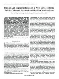
and PEP), is shown in Fig. 6. In the stationary part, a CD/DVD PUH is fixed on the frame and the probe is mounted below the CD/DVD PUH’s lens. The distance between the probe and the stage is adjusted by a tuning linear stage. Directly under the probe, our measured sample lies on the designed moving stage which is driven by the adaptive sliding mode controller compiled in MATLAB simulink. In the experiments, MATLAB xPC target is utilized for real-time control. Besides, Agilent N1231b A/D card is for laser interferometer sensing feedback, and NI 6733 D/A card with Copley Controls 412ce amplifiers are for output control signals.
, , and . In the next step, by differentiating the Lyapunov function candidate, we obtain:
(15) By choosing the adaptive law with σ-modification [14], the boundedness in the presence of modeling error term can be determined in the following: , (16) where are all positive diagonal matrices. By substitute Eq. (22) into Eq. (21), and choosing the high gain N to dominant the time-varying uncertainty , then we have
Fig. 6 The overall view of the AFM system
(17) By choosing
,
and add the term inequality:
to Eq. (17), we can obtain the following
(18) Since sliding mode control scheme involving saturation function belongs to boundary layer control, the analysis of sliding parameter S inside or outside the boundary layer should be taken into separate consideration. After considering two situations of the most conservative stability case, we apply Lyapunov stability theorem and can conclude that when
A. AFM Scanning Range Test In order to test the maximum scanning range, the large field positioning of the PEP is applied, where the task of stepping from 500 μm to -500 μm at t=1 sec and t=6 sec, in x-axis is demonstrated in Fig. 7. The total displacement is 1 mm with an rms error of 20 nm. Due to the symmetry structure design, the transition motion also proves that a total 1 mm displacement is achievable by the proposed stage PEP.
(19) Fig. 7 Step from 500 μm to -500 μm
which implies that and therefore . Lastly, we can further show that will converge to a residual set whose size is in the order of , which implies that such error performance can be improved by appropriate parameter choice. Through the following adaptive sliding mode controller which is based on PEP’s MIMO model, we can apply the similar controller to PAP in z-axis with only single input and single output. Further analysis can be found in our earlier work [12].
B. AFM Scanning Trajectory Test Since the AFM’s scanning trajectory is a combination of triangular wave motion and consecutive stepping, where the former is a 200 μm triangular wave with 0.5 sec transition time yielding the cyclic period with featuring time vector t = [0 0.5 4 4.5 8], over two axes of PEP. In Fig. 8 (a), the aforementioned triangular wave is applied to x-axis motion with ASMC. The worst straightness error in x-axis is calculated to be only . Because there’s no backlash or friction in PEP, the positioner turns very smoothly at the peak point of the wave motion. Moreover, due to the properties of linear current–force relation of the electromagnetic actuation and freedom of hysteresis effect, the slope in the figures is observed to be very linear.
V. EXPERIMENTAL RESULTS The overall view of the AFM system, including the stationary part (scanning tools) and the moving stage (PAP 899
Besides, consecutive steps are applied to y-axis motion, which is also a demonstration of the positioning ability of the PEP. The applied input is a composition of five consecutive 100 nm up steps and five consecutive 100 nm down steps in y-axis with ASMC. The average positioning error in rms is 20 nm, as shown in Fig. 8 (b). In this figure, each step is distinctive without overshoot.
VI. CONCLUSION In this paper, the design, implementation, and control of an AFM scanning instrument was presented. The compact design of PEP, consisting of a monolithic xy serial compliant flexure mechanism with compression spring, electromagnetic actuators, and an Eddy current damper is detailed. Moreover, a robust adaptive sliding mode controller, which is capable of dealing with the unmodelled parameters and external disturbances, is developed. In addition, a compact and low-cost CD/DVD PUH is applied, by which we can actually reduce the complex light path and the sensing error. Finally, with the help of both piezoelectric and electromagnetic actuations, a large scale scanning is achievable, and some experiments have verified the precision positioning and AFM’s appealing scanning abilities. To sum up, a large scale scanning AFM system has been proposed in this work.
(b) (a) Fig. 8 ASMC - (a) tracking a triangular wave in x-axis (b) consecutive steps in y-axis
VII. REFERENCES
C. AFM Scanning Results A standard measured sample is used to validate our AFM system. Here, the standard grid (see Fig. 9(b)) sample with a pitch of 15 μm ((peak : valley) = (9.8 : 5.2)), and the height of 0.24 μm is scanned. The large scale scanning trajectory of PEP involves 150 μm/8 secs triangular wave in x-axis, and 0.3 μm/ 8 sec consecutive steps in y-axis. The total scanning time is 400 seconds. As shown in Fig. 9 (a) and Fig. 9 (c), the presented figures indicate a frame size of 100 μm×15 μm shown on, an image with 2000×50 pixels, resulting in resolution of 50 nm and 300 nm in x- and y- dimensions, respectively. By careful evaluation, we found that the roughness is computed to be 14.55 nm and the straightness in y- axis is 1.364%. Without hysteresis, PEP is capable of scanning more undistorted image with scanning range larger than conventional ones.
[1] [2] [3]
[4]
[5] [6] [7]
[8]
[9] (a)
(b) [10]
[11]
[12] (c) Fig. 9 The AFM large range scanning (a) scanning trajectory of xy directions (b) measured sample (c) scanning result in the virtual 3D topography 100 μm × 15 μm image.
[13] [14]
900
G. Binning, H. Rohrer, C. Gerber, and E. Weibel, “Surface studies by scanning tunneling microscopy,” Physical Review Letters, vol. 49, pp. 57-61, 1982. G. Binning, C. F. Quate, and C. Gerber,“Atomic force microscope,” Physical Review Letters, vol. 56, pp.930-933, 1986. A. Sinno, P. Ruaux, L. Chassagne, S. Topcu, Y. Alayli, G. Lerondel, S. Blaize, A. Bruyant, and P. Royer, “Enlarged atomic force microscopy scanning scope: Novel sample-holder device with millimeter range,” REVIEW OF SCIENTIFIC INSTRUMENTS 78, 095107, 2007. A. Sinno, P. Ruaux, L. Chassagne, S. Topcu, Y. Alalyli, G. Lerondel, S. Blaize, A. Bruyant, P. Royer, “Enlarged Sample Holder For Optical Afm Imaging: Millimeter Scanning With High Resolution,” IEEE, 2009. Brian J Eves, “Design of a large measurement-volume metrological atomic force microscope (AFM),” Meas. Sci. Technol. 20, 084003, 2009. C. Werner, P. C. J. N. Rosielle, M. Steinbuch, “Design of a long stroke translation stage for AFM,” International Journal of Machine Tools & Manufacture 50, pp. 183–190, 2010. L. Petit, C. Prelle, E. Dore, F. Lamarque, and M. Bigerelle, “A fourdiscrete- position electromagnetic actuator: Modeling and experimentation,” IEEE/ASME Transactions on Mechatronics, vol. 15, no. 1, pp. 88–96, 2010. Shan-Tsung Lee, Kuan-Lin Huang, Jim-Wei Wu, and Li-Chen Fu, “Design and Control of Long Travel Range Electromagnetically Actuated System with Application to Precise Machining,” 2010 IEEE Multi-Conference on Systems and Control, September 8-10, 2010 C. Mei-Yung, H. Hsuan-Han, and H. Shao-Kang, “A new design of a submicropositioner utilizing electromagnetic actuators and flexure mechanism,” Industrial Electronics, IEEE Transactions on, vol. 57, no. 1, pp. 96–106, 2010. Kuan-Lin Huang, Yuan-Zhi Peng, Jim-Wei Wu, Mei-Yung Chen, and Li-Chen Fu, “Design and implementation of an electromagnetically damped positioner with flexure suspension,” 2011 IEEE Multi-Conference on Systems and Control, September 28-30, 2011. Yuen Kuan Yong, Sumeet S. Aphale, and S. O. Reza Moheimani, Senior Member, IEEE “Design, Identification, and Control of a Flexure-Based XY Stage for Fast Nanoscale Positioning,” IEEE Transactions on Nanotechnology, vol. 8, no. 1, January 2009. Shih-Hsun Yen, Jim-Wei Wu, Li-Chen Fu, “Apply tapping mode Atomic Force Microscope with CD/DVD pickup head in fluid,” American Control Conference (ACC), pp. 6549-6554, 2010. B. K. G. B.Bhushan, Hand book of tribology: McGraw-Hill, 1991. P. A. Ioannou, and J. Sun, Robust Adaptive Control, Prentice Hall, 1998.