drum is recognized by the potentiometer and fed into the electronic circuit where there is a conversion of the mechanical movement into electronic. And further ...
I J B E C H87I
International Journal of Biomedical Engineering andofConsumer Health Informatics Design and Implementation An Applanation Tonometer using Hollow Shaft Potentiometer Volume 3, Number 2, July-December 2011, pp. 87-94, ISSN: 0973-6727
Serials Publications
DESIGN AND IMPLEMENTATION OF AN APPLANATION TONOMETER USING HOLLOW SHAFT POTENTIOMETER Tincey Varkey1, V. Prabhu2, Ravichandran3, Gajendran4 and S.P. Angeline Kirubha 5
Abstract: Glaucoma is one of the leading causes of blindness. Glaucoma is a disease of the major nerve of vision, called the optic nerve. If glaucoma is not diagnosed and treated properly, it can progress to loss of central vision and blindness. Glaucoma occurs mainly due to the increased pressure inside the eye. In this project a tonometer is implemented using a hollow shaft potentiometer. Tonometry determines the pressure in the eye by flattening the corneal surface. There are many types of tonometers available. The most common being the applanation tonometer. Here, a hollow shaft potentiometer is used as an encoder rather than pressure sensors. This will be very cost effective. The tonometer’s doubling prism is placed against the front surface of the eye; this prism flattens the surface of the eye. The movement of the measuring drum is recognized by the potentiometer and fed into the electronic circuit where there is a conversion of the mechanical movement into electronic. And further, the ADC is used to convert this into the corresponding digital display. Moreover, the measuring range is calculated from 0 to 80mmHg. The diameter of the pneumatic face is 3.06mm so that it is comfortable to reach the cornea of the eye. The final display of the pressure in the eye is viewed in the LED segment display. This project is found to be very cost effective and the weight of the tonometer is less when compared with the earlier tonometer. Keywords: Glaucoma, applanation, tonometer, potentiometer, cornea, doubling prism.
glaucoma screening efforts as well as regular eye examinations are essential to detect glaucoma at the earliest possible stages. Advances in the field of medicine and electronics have helped in the conversion of a mechanical tonometer to a digital tonometer. Tonometry is very useful to doctors for detection of the pressure in the eye, or the intraocular pressure (IOP). In ophthalmology, tonometry is the procedure doctors perform to determine the intraocular pressure (IOP), the fluid pressure inside the eye. It is an important test in the evaluation of ocular conditions such as glaucoma. Most tonometers are calibrated to measure pressure in mmHg. Low IOP range: (10-16) mmHg Normal IOP range: (16-21) mmHg High IOP range: above 23mmHg An elevated IOP can be dangerous because people with varying degrees of IOP elevation may develop damage to the optic nerve. The optic nerve collects all of the visual information from the retina of the eye and transmits that information to the brain, where the signals are interpreted as vision. When changes occur in the optic nerve leading to decreased peripheral vision and loss of the nerve tissues, a diagnosis of glaucoma can be made.
1. INTRODUCTION 1.2 Background 1.1 Overview Technology is on high roll today and that has only made people expect more and more from it. The medical field is in no way an exception to this kind of growth. The demands on the technologies in medicine are much more specific because patients and doctors require maximum efficiency with comfort. Glaucoma is a disease in which the optic nerve is damaged, leading to irreversible loss of vision. It is often due to increased pressure of the fluid in the eye. Raised intraocular pressure is a significant risk factor for developing glaucoma (above 21 mmHg). Untreated glaucoma leads to permanent damage of the optic nerve and resultant visual field loss, which can progress to blindness. Intraocular pressure is a function of production of liquid aqueous humor by the ciliary processes of the eye and its drainage through the trabecular meshwork. Aqueous humor flows from the ciliary processes into the posterior chamber. Thus,
The first commonly used mechanical tonometer was designed and introduced by Hjalmar Schiotz in the early 1900s. The instrument was simple, easy to use, and relatively precise. It was quickly accepted and became the new gold standard beginning the 1910s. Innovations in calibration led to its increased use, and a tremendous amount of knowledge about the normal and glaucomatous eye was quickly acquired. Goldmann introduced an adjustment for ocular rigidity in the 1950s, which led to the development of the Goldmann applanation tonometer. The Goldmann tonometer displaces very little fluid that variations in ocular rigidity were then thought to be mostly negligible. This type of tonometry uses a plunger to indent the cornea. IOP is determined by measuring how much the cornea is indented by a given weight. The test is less accurate than applanation tonometry and is not commonly used today by ophthalmologists and optometrists.
88
Tincey Varkey, V. Prabhu, Ravichandran, Gajendran and S.P. Angeline Kirubha
1.3 Problem Statement There are many problems associated with the current trend in tonometry procedures. In the present tonometers that are used in India are generally exported from abroad which are quite expensive. As such the tonometers that are being manufactured in India are not precise and accurate. And the precision can be made with the help of sensors. But the availability of pressure sensors used for the medical purpose is also very limited. 1.4 Motivation The one method which has not been used in the advancements of Intraocular Pressure (IOP) measurement is the introduction of a hollow shaft potentiometer instead of pressure sensors. It will have a potentiometer which will make the mechanical movement of the measuring drum convert into electronics. And the electrical signal will be converted into digital using the Analog to Digital convertor. The IOP value is displayed in the 7 segment LED. The tonometer can also be charged to using a battery which is easily available so that the tonometer can retain its power in the system. 2. INTRODUCTION As mentioned earlier the project is about measuring the intraocular pressure of the patients using a hollow shaft potentiometer which is very essential for glaucoma patients. The aim of the project is to make the doctor visualize the pressure inside the eyes by having a digital display than the mechanical tonometers that are being used nowadays. This chapter will deal with the requirements to build a tonometric system, how the various components are connected to each other and the working of the system. This chapter holds the very essence of the project work. 2.1 HardwareAnd Software Required The project is composed mainly of hardware, but hardware and software are interdependent. A project cannot be designed to be totally a hardware one without any software at all. And the same goes for software since it meets hardware to be implemented. So in this project, hardware kit is developed where some software helps in the functioning. First going into the hardware requirements and then the software requirements.
The main part of the circuit is the potentiometer. The hollow-shaft potentiometer acts as an encoder which converts the movement of the measuring drum into a digital display. The data that is calibrated are sent to the microcontroller chip where the data’s are stored in the RAM. The microcontroller controls the data that are sent. The ADC converts the mechanical movement to a digital form. Thus in a nutshell, 1.
Voltage regulator
2.
Serial communication-RS232
3.
Hollow shaft POT-RH24PC
4.
Microcontroller- AT89C51
5.
ADC-MCP3202
6.
D-type Latch-74HC/HCT573
7.
7 digit LED display
8.
Doubling Prism
2.3 Software Requirements As mentioned earlier, software is used to enhance hardware designs. The microcontroller recognises only the assembly level language programming. But the assembly language is very tough to write and execute because it is extremely long and rather complex. This demands a detailed knowledge even about the architecture of the microcontroller. So in order to come out of this difficult situation, mnemonics are used for the microcontroller to function. The other software that is used here is for the designing of the PCB board which is OrCAD software. With the help of this software the various components that should be placed over the board is designed using OrCAD Capture. To mention the foot prints and the legends OrCAD PCB Editor is used. There are no much codes in this software as we are using only the instruction set for the microcontroller to function. 2.4 Block Diagramrs 232
2.2 Hardware Requirements To start with, for any circuit the first and foremost requirement is the supply. There are several types of supplies for various circuits depending on the requirement. But in this project, household current supply is being used. The ordinary domestic supply itself is 230V and cannot be given directly to any electronic devices. Here a charger is used to make the tonometer battery operated, wherein the supply of 230V is converted to 3.7V. This voltage is being supplied to the entire circuit board and is maintained at the same voltage using the voltage regulator.
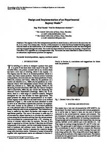
Figure 2.1: Block Diagram of the System Operation.
2.4.1 Description of the Block Diagram The supply is given to the voltage regulator. From the output of the regulator the voltage passes on to the other components. Here, the prism is placed on the cornea by the doctor with the help of the measuring drum moving in a rotational manner.
Design and Implementation of An Applanation Tonometer using Hollow Shaft Potentiometer
This movement is sensed by the hollow shaft potentiometer (POT) which is used to convert the mechanical rotation of the measuring drum into electronics. There is a communication between the Processor and the ADC. The processor fetches, executes and decodes the opcode instructions. The digital value is displayed on the 7 segment LED display. The potentiometer and the embedded processor are interfaced using RS232. 3. HARDWARE DESCRIPTION 3.1 Introduction to Target Processor Microcontroller differs from a microprocessor in many ways. First and the most important is its functionality. In order for a microprocessor to be used, other components such as memory, or other components for receiving and sending data must be added to it. On the other hand, microcontroller is designed to be all of that in one. No other external components are needed for its application because all necessary peripherals are already built into it. Thus, saving time and space needed to construct devices. This chapter deals with the study of microcontrollers. 3.2 Description to Embedded Controllers Microcontroller as the name suggests, are small controllers. These are like single chip computers that are often embedded into systems to function as processing or controllers unit. The key features of microcontrollers include: •
High integration of Functionality
Microcontrollers sometimes are called single chip computers because they have on chip memory and I/O circuitry and other circuitries that enable them to function as standalone computers without other supporting circuitry. •
Field programmability, Flexibility
Microcontrollers often use EEPROM or EPROM as their storage device to allow field programmability so they are flexible to use. Once the program is tested to be correct then large quantities of microcontrollers can be programmed to be used in embedded systems. •
Easy to Use
Assembly language is often used in microcontroller and since they usually follow RISC architecture, the instruction set is small. The development package of microcontrollers often includes an assembler, a simulator, a programmer to “burn” the chip and demonstration board. Some packages include high level language compiler such as a C compiler and more sophisticated libraries. The main units of a microcontroller are discussed below: 3.2.1 Memory Unit Memory is part of the microcontrollers whose function is to store data. The easiest way to explain it is to describe it as one big closet with lots of drawers. If we suppose that we marked the
89
drawers in such a way that they cannot be confused, any of their contents will then be easily accessible. It is enough to know the designation of the drawer and so its contents will be known for sure. Memory components are exactly like that. For a certain input the contents of a certain addresses memory location are got. Two new concepts are brought out here: addressing and memory locations. Memory consists of all memory locations, and addressing is nothing but selecting one of them. This means that we need to select the desired memory location on one hand, and on the other hand we need to wait for the contents of that location. Besides reading from a memory location, memory must also provide for writing onto it. This is done by supplying an additional line called control line. This line is designated as R/W (read/write). Control line used in the following way: if r/w=1, reading is done, and if opposite is true then writing is done on the memory location. Memory is the first element, and need few operation of the microcontroller. 3.2.2 Central Processing Unit Three memory locations are added to a specific block that will have to build a capability to multiply, divide, subtract and move its contents from one memory location onto another. The part that is just in is called “Central Processing Unit” (CPU). Its memory locations are called registers. Registers are therefore memory locations whose role is to help with performing various mathematical operations or any other operations with data whatever data can be found. Looking at the current situation, the two independent entities (memory and CPU) are interconnected and thus any exchange of data is hindered, as well as its functionality. If for example, we want to add the contents of two memory locations and return the result again back to the memory, a connection between memory and CPU is needed. There should be some way though data goes from one block to another. 3.2.3 Input Output Unit The locations that are added are called “ports”. There are several types of ports: Input, output or bidirectional ports. When working with ports, first of all it is necessary to choose which port is needed to work with, where to send the data or which port to take it from. 3.2.4 Serial Communication Serial communication is often used either to control or to receive data from an embedded microprocessor. Serial communication is a form of I/O in which the bits of a byte begin transferred appear one after the other in a timed sequence on a single wire. Serial communication has become the standard for intercomputer communication. The MAX3232E have two receivers and two transmitters. The MAX3232E features a 1µA shutdown mode that reduces power consumption in battery-powered Portable systems. The MAX3232E receivers remain active in shutdown mode, allowing monitoring of external devices while consuming only 1µA of supply current.
90
Tincey Varkey, V. Prabhu, Ravichandran, Gajendran and S.P. Angeline Kirubha
The MAX3232E are pin, package, and functionally compatible with the industry-standard MAX232. When working with it the port acts like a memory location. Something is simply being written into or read from it, and it could be noticed on the pins of the microcontroller.
It is used for high resolution single turn manual and automatic settings and slow feedback. It has very good rotational life, reasonable good linearity and resistancetolerance. The hollow shaft is suitable for 5mm diameter shaft interconnection.
3.3 Features of AT89C51
3.5 ANALOGTO DIGITAL CONVERTOR (ADC 3202)
The AT89C51CC03 is a member of the family of 8-bit microcontrollers which provides high flexible and cost effective solutions to many embedded control applications.
ADC is an electronic device that converts an input analog voltage or current to a digital number proportional to the magnitude of the voltage or current.
Following are the features:
The MCP 3202 A/D Convertor employs the Successive Approximation Resistor (SAR) architecture. The communication with device is done using a3 wire Serial Peripheral Interface (SPI) compatible interface.
1.
It has 256 bytes of internal RAM compared to 128 in standard 8051.
2.
It is low power; high performance CMOS 8-bit microcomputers with 8K bytes of flash programmable and erasable read only memory (PEROM).
3.5.1 Features of ADC3202 •
12-bit resolution.
3.
Fully static operation: 0Hz to 24 MHz.
•
On-chip sample and hold.
4.
It has 32 programmable I/O lines i.e. it has 4 ports (port 0 to port 3).
•
SPI serial interface.
•
Single supply operation: 2.7V – 5.5V
5.
Three 16-bit Timer/counter is present inside the microcontroller to strengthen its operation, compared to only 2 timers in standard 8051.
•
Low power CMOS technology.
•
Industrial temp range: –40°C to +85°C.
The device is manufactured using ATMEL’s high density non volatile memory technology and is compatible with the industry standard 80C51 and 80C52 instruction set and pin out.
3.5.2 Applications
6.
3.3.1 Description The AT89C51 (PLCC package) is a low-power; high performance CMOS 8-bit microcomputer with 8K bytes of Flash programmable and erasable read only memory (PEROM). The device is manufactured using Atmel’s high density nonvolatile memory technology and is compatible with the industry standard 80C51 and 80C52 instruction set and pin out. The Atmel AT89C51 is a powerful microcomputer which provides a highly-flexible solution to many embedded control applications. 3.4 Hollow Shaft POT-RH24PC The hollow-shaft 22mm precision conductive plastic potentiometer has a universal adapter flange for flexible mounting. The hole inside is flattened for easy fixation of the potentiometer on any shaft. It is an ideal cost for any rotary shaft movement. 3.4.1 Features of RH24PC •
Conductive plastic element with high resolution.
•
Plastic housing.
•
Resistance range 1kOhms to 100kOhms ± 20%.
•
Standard linearity tolerance ± 1, 5%.
•
Rotational life: 2 million shaft revolutions.
•
Mechanical angle: 340 °.
•
It can be used as a Sensor Interface.
•
It can be used in Processing Control.
•
Used in the process of Data Acquisition.
•
Also used in Battery operated systems.
3.6 Voltage Regulator A voltage regulator is an electrical regulator which is designed automatically to maintain a constant level of voltage. Depending on the design, it may be used to regulate one or more AC or DC voltages. The LD1117 is a LOW DROP Voltage Regulator able to provide up to 800mA of Output Current. Concerning fixed versions are offered the following Output Voltages: 1.2V, 1.8V, 2.5V, 2.85V, 3.0V 3.3V and 5.0V. 3.6.1 Specifications Number of Outputs:
1
Number of pins:
3
Input Voltage:
3.30V
Output Current:
800mA
Output Voltage:
3.30V
Operating temperature:
125 °C (max)
Mounting type:
Surface Mount
3.7 Octal D-Type Latch (74HCT573) The 74HCT573 are high speed Si-gate CMOS devices. The 74HCT573 is an octal D-type transparent latch featuring
Design and Implementation of An Applanation Tonometer using Hollow Shaft Potentiometer
separate D-type inputs for each latch and 3-state output. It is also used to store the information. The latch enable (LE) input and an output enable ( OE ) input are common to all latches. 3.7.1 Features of 74HCT573 •
Inputs and outputs on opposite sides of package allow easy interface with microcontrollers.
•
It is useful as input or output port for microcontrollers.
•
It has common 3-state output enable input.
3.8 Seven Segment Led Display A seven-segment display is a form of electronic display device for displaying decimal numerals that is an alternative to the more complex dot-matrix displays. As the name indicates it is composed of seven elements. Seven-segment displays are widely used in digital clocks, electronic meters, and other electronic devices for displaying numerical information. The seven segment displays are designed for use in wide temperature and high humidity environments. Backlighting is available in both reflective and transreflective configu-
Figure 4.1: Schematic Diagram of the Whole Circuit Model.
91
rations. The 7 segment display is excellent for displaying text on portable instruments due to its low power requirements. Some of its applications are found to be in: • Medical • Commercial • Industrial Because of its low cost it is also suitable for disposable devises and instruments. Here, the use of the LED segment is for displaying the value of the pressure inside the eye digitally. Total quantities of 4 LED displays are used here. 3.9 Doubling Prism The doubling prism that is used in the tonometer setup is used to flatten the corneal surface. The prism is made of acrylic material which is basically PolyMethylMetaAcrylate (PMMA). The doubling prism helps to focus the inside portion of the eye very clearly with the help of a microscope in the slit lamp. For patients with astigmatism, the view would not be clear so for this purpose the doctors turn the prism from the white mark to the red mark. 4. CIRCUIT DIAGRAM OF THE WHOLE MODEL
92
Tincey Varkey, V. Prabhu, Ravichandran, Gajendran and S.P. Angeline Kirubha
4.1 Hardware Description of the Mechanical Part Applanation tonometer for the measurement of IntraOcular Pressure is designed to be mounted on the microscope permanently. When the tonometer is in use it can be swung forward just in front of the microscope and exact centering of the prism with the left eye piece engaged with the notch. Illumination through the built-in cobalt filter projected to the plastic measuring prism for flattening the vertex of the cornea gives reflection–free observation of split images. 4.2 Mechanical Assembly of the Tonometer There are generally 12 stages in the assembly of the Tonometer: A. Main body assembly. B. T-joint assembly. C. Weight support assembly. D. Rod attachment assembly. E. Plunger assembly. F.
Pressure rod assembly.
12. Fix the pressure rod in the rod attachment along with bearing, spring, bush, cone bush, cone bush spring and top cover. 13. Fix the prism housing in top of the pressure rod. 14. Fix the plunger housing in tonometer body along with adjustment screw and nut, plunger, spring. 15. Plunger movement rod is connected with rod attachment. 16. Fix the copper washer in body outside worm shaft one side. 17. Fix calibrated disc in worm shaft on end along with star washer, cir clip, brass disc and felt washer. 18. Fix the knurled knob in calibrated disc. 19. Fix the knurled knob and guide push in the worm shaft end. 20. Fix the tonometer body front and back covers and tight the screws. 21. Fix the main shaft in the bottom cover along with guide pin and tight screw.
G. Worm shaft assembly.
22. Fix the adjustment assembly in mount holder along with rod, bush, bearing, washer and lock screw.
H. Roller assembly.
23. Fix the mount holder in main shaft.
I.
Main shaft assembly.
24. Fix the mount base in mount holder.
J.
Check rod assembly.
25. The mount base is used to fix the slit lamp head.
K. Mount base assembly. L. Unit center assembly.
4.4 Tonometry Procedure 1.
Set the measuring drum on 1(1 gm) equals 10mmHg. Make sure to align the white line on the probe carrier with the zero or 180 degree marker of the probe. Place the light source 60 to 65 degrees temporal to the probe.
2.
Use wide-open diffuse illumination, bright illumination, and cobalt blue filter and 16x magnification.
3.
Always align the patient as in a normal slit lamp examination.
4.3 Work Instruction 1.
Take the tonometer body.
2.
Assemble worm shaft guide washer and pin in worm shaft.
3.
Assemble the worm shaft in the tonometer body along with roller housing and worm guide bush.
4.
Tight the worm guide bush screw.
5.
The other end of the worm fixes 11mm bearing and check for the movement.
4.
Make sure the patient keeps the head tightly against the headrest.
6.
Fix roller holder in the roller housing and cover it with the roller housing guide plate.
5.
7.
Fix bottom cover and check for free movement.
8.
Assemble the weight support align pin tonometer body M3 hole and lock the M3 screw.
Anesthetise both the eyes of the patient. Place a fluorescein paper strip near the external canthus in the lower conjuctival sac. After a few seconds the lacrimal fluid is sufficiently coloured and the paper can be removed.
6.
Do not rub the eyes for at least 20 minutes.
9.
Fit the T-joint in weight support assembly.
7.
The optical system and tonometer are “not aligned” and must be offset by 5 to 10 degrees. The view of the probe and the mires are seen only with one eye (Monocular).
8.
Move the slit lamp towards the patient. When the probe touches the cornea, a limbal glow will be seen. At this point the mires are seen through the slit lamp.
10. Then fit weight support assembly in between weight support and align pin and check for free movement. 11. Fix the rod attachment along with counter weight in between rod attachment bush and guide screw and check the rod attachment free movement.
Design and Implementation of An Applanation Tonometer using Hollow Shaft Potentiometer
9.
The pressure on the eye is increased by turning the measuring drum in the tonometer until the inner borders of the two fluorescein rings just touch each other.
93
4.7 Instructions to The Patient 1.
The patient’s head should be pressed firmly against the chin and forehead rest. If necessary a head rest band can be used.
2.
The patient is instructed to look straight ahead. If necessary a fixation target can be used to steady the eyes.
3.
The patient should keep his eyes wide open during the examination.
4.8 Measurement 10. Now the measuring drum is read, the amount of pressure applied is calculated by multiplying it with ten which will give the intraocular pressure in mmHg on the digital display. 4.5 Description of the Measuring Principles The cornea is flattened with a prism made of plastic. The anterior surface is flat, its diameter being 7.0mm. The borders are rounded in order to avoid injuring the cornea. The prism is brought into contact with the cornea by advancing the slit lamp. Then, by turning the measuring drum which regulates the force applied to the pressure arm, the tension on the eye is increased until a surface of known and constant size of 3.06mm diameter = 7.354mm2 is flattened. Goldmann based his concept of tonometry on a modification of the Maklakov-Fick law. This law states that an external force (W) against a sphere equals the pressure in the sphere (Pt) times the area flattened (applanated) by the external force (A). W = Pt X A. 4.6 Preparing the Slit Lamp and the Tonometer 1.
Before measuring make sure that the eye pieces are correctly focussed.
2.
Bring the blue filter into the beam of the slit lamp and open the slit diaphragm completely.
3.
When the tonometer is used, the fixation base has to be mounted first. Remove the screw on top of the cylindrical body of the microscope.
4.
Swing the slit lamp to the left. Bring the tonometer from the right in front of the microscope where a notch position ensures the exact centering.
5.
Observation of the flattened area of the cornea is made through the left eye piece.
6.
Clean the measuring prism with a disinfectant that does not damage the prism.
7.
Bring the pressure arm into the notch position so that the axis of the measuring prism and the microscope coincide.
8.
Set the measuring drum at 1. If the prism touches the cornea without any force being applied, the pressure arm will vibrate and this may disturb the patient.
1.
Anaesthetise both eyes with 2-3 drops of novesine (Dorsacaine) 0.4% within half a minute. Both eyes must be opened and there should be control in the movements of the lids during the prolonged examination.
2.
With the cornea and bi-prism illuminated by a cobalt blue light from the slit lamp, the bi-prism is brought into gentle contact with the apex of the cornea.
3.
The pressure on the eye is then increased by turning the measuring drum on the tonometer until the inner borders of the two fluorescein rings just touch each other.
4.
The fluorescent semicircles are viewed through the prism and the force against the cornea is adjusted until the inner edges overlap.
5.
The IOP is then read directly from a scale on the tonometer housing.
5. RESULTAND CONCLUSION Thus an applanation tonometer with the help of potentiometer was designed. The doubling prism is used to flatten the corneal surface by rotating the measuring drum. The hollow shaft potentiometer is used to convert this movement into electronics. Thus the rotational movement is converted into electronics and displayed in digital format with the help LED display. ACKNOWLEDGMENT The authors wish to thank the Government Hospital of Villupuram for efficient co-operation and examination of the tonometer quality. Special thanks to Dr. V Prabhu and Mr. Ravichandran and to Mr. Gajendran without whom this project wouldn’t be successful. REFERENCES [1]
Antti Ilmari Kontiola, “A New Induction-Based Impact Method for Measuring Intraocular Pressure; Acta Ophthalmologica Scandinavica 2000.
[2]
Andrzej Hachol, Jan Dziuban, Andl’zej Bochenek, “Ophthalmic Tonometer with Silicon Micromachined Structure”; Sensors and Actuators -issue 7,18 July 1996.
[3]
Per Hallberg, Christina Linde´n, Tomas Ba¨ cklund Anders Eklund, “Symmetric Sensor for Applanation Resonance Tomometry of the Eye”; International Federation for Medical and Biological Engineering, 26 January 2006.
94
Tincey Varkey, V. Prabhu, Ravichandran, Gajendran and S.P. Angeline Kirubha “Automated Segmentation of the Optic Nerve Head for Diagnosis of Glaucoma;”Medical Image Analysis, 8 April 2005.
[2]
Power electronics: Circuits, Devices and Applications. By Muhammed H.Rashid.
[3]
Linear Integrated Circuits. By Roy Chowdary.
[5]
Mei-Ling Huang, Hsin-Yi Chen, Jian-Jun Huang, “Glaucoma Detection using Adaptive Neuro-Fuzzy Inference System;”, Expert Systems with Applications issue, 32- 2007.
[4]
[6]
Kontiola AI (1997), “A New Electromechanical Method for Measuring Intraocular Pressure”; Documenta Ophthalmologica 93: pp. 265-276.
Comparison of Intraocular Pressure Measurements with the Digital Tonometer and the Goldmann Applanation Tonometer. By Michael W. Meyer, Roland Gockeln, Ludwig Hoy, Andrea Meyer, Carl Erb.
[7]
Stodtmeister R (1998), “Applanation Tonometry and Correction According to Corneal Thickness;” Acta Ophthalmol Scand, 76: pp. 319-324.
[8]
Lawton J (1967):, “The Incidence of Schio¨tz-Applanation Disparity”; Arch Ophthalmol, 77: pp. 305-308.
[4]
M
.
W
o
l
f
,
K
.
D
o
n
a
t
h
,
H
.
N
i
e
m
a
n
n
,
G
.
M
i
c
h
e
l
s
o
n
,
BOOK REFERENCES [1]
The 8051 Microcontroller and Embedded Systems. By Muhammed Ali Mazidi,Janice Gillispie, Mazidi Rolin D.McKinlay.
URL 1. 2. 3. 4. 5. 6. 7. 8. 9.
www.microchip.com www.ophthalmologyweb.com www.pacificu.edu/optometry www.megacraft.net www.medicinenet.com www.megauto.com www.66vision.com www.alibaba.com www.keeler.com