DESIGN OPTIMIZATION OF CUSTOM ENGINEERED SILVER-NANOPARTICLE THERMAL INTERFACE MATERIALS Viral Chhasatia, Fan Zhou, Ying Sun∗, Liwei Huang, and Howard Wang State University of New York at Binghamton Mechanical Engineering Binghamton, NY 13902, USA ∗ Phone: (607)777-3881 Fax: (607)777-4620 Email:
[email protected]
Δεp δ ε ε ′f
ABSTRACT Thermal interface material (TIM) is a major hurdle in heat flow for typical chip/heat sink assemblies. In many electronic devices, hot spots occur in areas of high activity during the device operation. These hot spots can lead to high thermal gradients, which in turn result in performance and reliability hindrances. The elevated, non-uniform power density confronted with conventional TIMs that contain a uniform layer of high thermal conductivity material for the entire chip can be extremely insufficient in many applications. In this paper, a custom engineered, Ag-nanoparticle (Ag-NP) TIM that targets directly to the high power density region is introduced for achieving better thermal-mechanical-electrical performance at low cost. These nanoparticles can be inkjet printed on hot spots and sintered at a relative low temperature (~120°C) to create a continuous metallic layer that is in good contact with both the chip and heat sink, whereas the conventional particle-laden TIM covers the lower power density area. A computational model is developed to examine the overall thermal performance and reliability of the hybrid Ag-NP/conventional TIM as a function of the bondline thickness, applied pressure, deposition pattern, and surface roughness. The results show great improvements compared with a high-performance indium solder.
strain amplitude bondline thickness, µm strain fatigue ductility coefficient
εf
true fracture ductility ν Poisson ratio Subscripts eff effective s surface 0 stress free stage 1. INTRODUCTION Power dissipation in electronic devices is projected to increase over the next five to ten years to the range of 150250 W/cm2 for high performance applications [1]. In a typical chip heat sink assembly, the thermal interface material (TIM) is the major hurdle in heat flow. Despite 20+ years of intensive R&D, the in-situ thermal conductivities of thermal interface materials remain in the 1-4 W/m-K range based on heterogeneous mixtures of conducting solids in polymer matrices. In addition, the temperature distribution throughout an electronics device can be extremely nonuniform. Hot spots often occur in areas of high activity during device operation. These hot spots can lead to excessive stresses on the chip, and result in performance and reliability hindrances.
KEY WORDS: Thermal interface materials, nanoparticles, hot spot, reliability, design optimization NOMENCLATURE A area, m2 ar aspect ratio c fatigue ductility exponent d surface roughness, µm E Young’s modulus, GPa k thermal conductivity, W/(m⋅K) number of cycles to failure Nf P pressure, Pa Q heat flux, W R thermal resistance, K/W T temperature, K Greek symbols α coefficient of thermal expansion, K-1
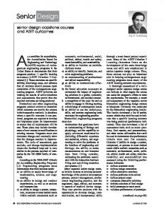
351K 347 343 339 335 331 327 Fig. 1. Temperature contour of air-cooled Intel Pentium 4 Northwood.
1
978-1-4244-1701-8/08/$25.00 ©2008 IEEE
419
Figure 1 shows the simulated temperature contours of an Intel Northwood processor when a constant heat transfer coefficient is applied to the top and bottom surfaces. Undesired dramatic temperature contours are observable, with T = 351K at hot spots and 327K in low power density region. This suggests that the elevated and non-uniform power density confronted with uniform, traditional cooling methods can be insufficient in many cases. Custom engineered, nano-structure enhanced TIMs that target directly to the high power density region could offer a superior cooling solution in electronics packaging.
molecules, which prevent Ag-NPs from coarsening, also make them processible in organic solvents. After printing, solvent is dried to leave NP thermal paste on the substrate. The composition of various components in the paste will be tuned to optimize processibility and the thermo-mechanical performance of the final TIM. To promote the solid contact with silicon wafer and other surfaces, a small amount of other nanoparticles such as Pd, Sn, Au, etc. will be added to the paste. Paste formulation will initially take the input from simulation and modeling results and further refined with iterative measurements and testing. Because of the intricate sintering process of converting from Ag-NPs to continuous Ag films, we expect a good paste formulation would result from a good balance between easier processing and better performance. Various surface chemistry designs are possible. For one type of Ag-NPs deposited on a substrate, a heat treatment at ca. 130 oC drives away the waxy organic molecules in the nanoparticle shell, triggering the fusion of nanoparticles to form a continuous metallic layer. Low temperature processing is desirable for reducing the residual stress between the TIM and chip/heat sink surfaces. We are also experienced with ink formulation for optimizing the printability and performance.
The key objective of this paper is to provide optimal design strategies toward custom engineered high-performance, highreliability, cost-effective TIMs for addressing specific application needs. The general principle is combining various materials with distinct thermal and thermo-mechanical performance budgets for the highest performance/cost ratio. This approach is enabled by recent advances in nanomaterials and processing technologies [2]. Inkjet-printed nanostructured and conventional TIM pastes allow engineers to focus on designs and configurations that meet the application requirements at the lowest possible cost. The Ag-NP TIM fabrication methodology is described in Section 2. In Section 3, the thermal performance of this hybrid Ag-NP/conventional TIM is first compared with an indium solder and then examined as a function of surface roughness and applied pressure. The thermal-mechanical properties of the hybrid TIM is investigated using the standard accelerated thermal cycling test. The effects of applied pressure, bondline thickness, Ag-NP deposition pattern on the TIM reliability are examined in Section 4. The hybrid TIM design optimization is explored in section 5. A brief conclusion is given in Section 6.
(a) As-deposited Ag-NPs
200 nm
2. AG-NP TIM FABRICATION METHODOLOGY Fabricating a laterally heterogeneous TIM structure with arbitrary patterns at a low cost has become possible with advances in inkjet printing technology. We currently use a desk-top inkjet printer manufactured by FUJIFILM Dimatix, which uses nanoparticle-containing inks with relatively low viscosity (at ca. 10 cp) to print patterns with features typically greater than 50 μm. By using an aerosol printer from Optomec, we can also deposit fine features with a resolution of 10 μm and arbitrary thickness using inks of much higher viscosity (up to ca. 5000 cp). To construct a TIM for a surface with the temperature distribution as shown in Fig. 1, thermal pastes containing Ag nanoparticles (AgNPs) of 5-10 nm in diameter can be deposited on the hot spots while the conventional metal-particle-laden TIM is deposited to cover the low power density areas. The thermal paste deposition can be performed on one or both surfaces in contact.
(b) sintered Ag film
Fig. 2. SEM micrographs of (a) as-deposited and (b) sintered Ag-NP film. One major advantage of this is that the high-performance AgNP pastes apply only to the hot spot of chips. Inkjet printing techniques will be used to direct the paste to the location of hot spots. The thickness of the paste layer will be adjusted according to the roughness of the solid surfaces (e.g., those of lid, die or substrate in the case of high performance electronics packaging) so that upon processing Ag-NPs would fill all interfacial voids. This layer therefore conforms to the roughness features of the solid surfaces, connecting from one solid surface to the other with high thermal conductivity passages. Another major advantage is the low sintering temperature treatment (at ca. 130 oC), which would minimize the residual stress while the device is operating at a similar temperature. The elimination of the waxy organic molecules in the nanoparticle shell from the chip assembly
The NP-containing inks for inkjet printing comprises of AgNPs and resin monomers suspended in organic solvent. The Ag-NPs are synthesized in house using wet chemistry methods. These Ag-NPs are coated with small organic
2 420
could also be challenging. A good design of paste patterning will be needed to include diffusion channels for the organic molecules to leave the assembly.
minutes at higher sintering temperatures. The residual organic content would affect the transport properties of sintered films. Here, electric resistance is measured for indirect assessment of the thermal conductivity of the sintered Ag-NP films, since both are related to the metallic passage. Figure 4a shows the time and temperature dependent electric resistance. A comparison implies that resistance of sintered film is very sensitive to the sintering temperature. That is further illustrated in Fig. 4b for Ag-NP films after 3 min sintering at various temperatures. The reduction of organic materials is of one decade at low and high temperatures, whereas the resistance varies over more than 7 decades.
We have studied the sintering process of Ag-NPs using a variety of techniques including thermal, microscopic and scattering techniques. Figure 2 shows the SEM micrographs of as deposited Ag-NP films (upper panel) showing individual particles and the cross-section view of the sintered contiguous Ag film on a Si wafer (lower panel). In addition, ion beam scattering could offer information regarding the composition, depth profile, and film density upon sintering. The analyses will indicate the loss of organic species with annealing from the diminishing hydrogen signal in forward recoil spectrometry (FRES) spectra as a function of annealing time and temperature. Figure 3a shows hydrogen peaks of FRES spectra of as-cast and Ag-NP films after various sintering times at 80 oC. The H-signal decreases with sintering time, indicating that sintering at a temperature as low as 80 oC for a time as short as a few minutes is sufficient to drive majority of hydrocarbon away from the film.
The sensitivity of the dependence of the residual hydrocarbon on sintering temperature and time are rather different. High temperature sintering could greatly shorter the processing time while result in purer Ag film and better thermal performance. However it is expected that both the residual stress and the TIM modulus will be high. The thermomechanical reliability could be inferior. On the other hand, sintering at lower temperatures takes longer time; the thermal performance may be compromised to superior mechanical properties.
Energy (MeV) 10
0.5
0.6
0.7
(a)
0.8
0.9
As-cast 1 min
8
10
6
(a)
7
10
6
2 min
4
Resistance (Ω)
Normalized Yield
8
0.4
4 min 10 min
2
60 min
0 50
100
150
200
10
5
10
4
10
3
10
o
80 C o 100 C o 120 C o 140 C
2
10
1
10
Channel
0
10
1.0
-1
(b)
0
5
o
80 C o 100 C
10
15
20
Annealing time (min) 8
10
0.6
(b)
7
10
6
10 0.4
Resistance (Ω )
Residual H fraction
0.8
0.2
0.0 0
10
1
10
100
time (min)
Fig. 3. (a) The hydrogen peak in FRES spectra of Ag-NP films annealed at 80 oC for various times, and (b) the normalized residual hydrogen analysis for Ag-NP films annealed at 80 oC and 100 oC for various times.
5
10
4
10
3
10
2
10
1
10
0
10
-1
10
80
100
120
140
160
o
Temperature ( C)
Fig. 4. The electrical resistance of Ag-NP films (a) sintered at various temperatures for various times, and (b) sintered at various temperatures for 3 min.
The fraction of residual hydrogen (equivalently the organic content) in sintered films is obtained from the integrated total H counts normalized by the as-cast ones. The time variations of residual H-fraction in Ag-NP films sintered at 80 oC and 100 oC are shown in a semi-logarithm scale in Fig. 3b. The symbols are experimental data and the dashed lines are guide to the eye. The organic content decreases with the logarithmic sintering time, typically to below 10% after a few
Upon the fusion of nanoparticles, a contiguous metallic layer conform the roughness features of the solid surfaces. Since the seamless metallic contacts have formed during the assembly, pressure is not required for maintaining the TIM performance. However, pressure is needed during the assembly to form conformal metallic layer and to
3 421
accommodate the volume reduction due to the loss of organic molecules in sintering. 3. THERMAL PERFORMANCE In this section, the thermal performance of the hybrid AgNP/conventional TIM is first compared with a highperformance indium solder currently used in high-end microelectronic industry. The effects of the substrate surface roughness and device applied pressure on the thermal performance of hybrid TIM are then investigated in detail. Here, a 60W 20×20mm2 Si device with a hot spot of 2×2mm2 and 15W power generation is studied. A 40×40mm2 41-fin heat sink is used to dissipate heat and the ambient temperature is at 298K. Properties and dimensions of the various components in this chip/heat sink assembly are listed in Table 1 and the schematic illustration of the model geometry is shown in Fig. 5. The Ag-NP paste (effective thermal conductivity of 100 W/m-K) is only applied on the hot spot, with the conventional particle-laden TIM (effective thermal conductivity of 3 W/m-K) on the low power-density area. We compare this TIM configuration with an indium TIM for the entire Si device. In both cases, the TIM thickness is assumed to be of 50μm. Due to the symmetry boundary condition, only a quarter of the device is simulated and the results are shown in Fig. 6. total of 41 fins
(a) Inkjet-printed hybrid Ag-NP/conventional TIM
°C (b) Indium solder for the entire chip Fig. 6. Temperature distribution for two TIM designs.
2
in mm
h=100W/m -K
Ag-NPs
Cu heat sink
0.25 10
0.75 0.2
ambient T=298K
TIM
Si device
hot spot
Fig. 5. Schematics of a typical chip/heat sink assembly. Table 1.Materials properties. component dimension(mm) power (W/m3) k (W/m-K) E (GPa) ν α (10-6K-1) component dimension(mm) power (W/m3) k (W/m-K) E (GPa) ν α (10-6K-1)
Pentium 4 chip (Si) 20×20×0.5 2.25×10⁸ 148 180 0.22 2.8
hot spot (Si) 2×2×0.5 7.5×10⁹ 148 180 0.22 2.8
thermal paste (Ag-Silicone) 20×20×0.05 − 4 1 0.3 12
TIM (Ag-NP) 2×2×0.05 − 100 76 0.37 20
TIM (indium) 20×20×0.1 − 30 10.6 0.45 32.1
heat sink (Cu)
As shown in Fig. 6, the temperatures of the silicon device in both cases are far below the 105°C threshold value. However, our hybrid Ag-NP/conventional TIM has the potential of reducing the bondline thickness to 10~30 μm as compared to ~100 μm for most indium solders. In addition, since Ag-NPs are only deposited on the hot spot, the conventional particle-laden TIM located elsewhere can help reduce the stresses due to CTE mismatch induced by changes in temperature and/or relative humidity, and therefore improve the reliability of the entire device. In many high-end applications, where an integrated heat spreader (IHS) is used, a low modulus TIM is often desirable for maintaining the natural curved shape of the die stress [3]. Our hybrid AgNP/conventional TIM is expected to perform very well with the IHS due to the conformable nature of the particle-laden TIM region. Substrate surface roughness and TIM applied pressure In practice, the Ag-NP TIM inkjet printed and sintered between the silicon device and heat sink cannot be brought into perfect contact with either the Si chip or heat sink due to inevitable substrate surface roughness, and hence results in small gaps of low thermal conductivity at the Ag-NP TIM/chip and Ag-NP TIM/heat sink interfaces. Although a pressure on the heat sink may mitigate this phenomenon, it is necessary to analyze the effect of surface roughness on the TIM thermal performance. Here, the thermal resistance due to surface roughess, Rs, is calculated by d (1) Rs = k eff A
40×40×10 − 400 128 0.36 16.4
and
4 422
ΔT (2) Rs where keff is the effective thermal conductivity of a rough surface and is assumed to be 1W/mK, A is the area of the AgNP TIM, d is the surface roughness, and Q is the heat flux flowing through the hot spot. The surface roughness at Si/TIM and TIM/HS interfaces are assumed the same and vary between 0 and 2ȝm.
can be easily squeezed to fill out any gaps at the interfaces. Figure 9 shows the effect of applied pressure on surface roughness of an already sintered Ag-NP TIM, assuming the Ag-NP TIM as a homogenous layer of elastic material. It is clear that, with an applied pressure up to 0.5MPa, the void size created by surface roughness will only reduce 2% compared to that without pressure. However, in reality, the effect of pressure on surface roughness is a function of the heterogeneous Ag-NP microstructure that is determined by the Ag-NP ink formula, volume fraction, sintering temperature, and other processing parameters. A separate model for the squeezing flow upon sintering of the Ag-NPs is needed to further quantify this effect.
Q=
Figure 7 shows the temperature distribution across the TIM region for surface roughness of 0, 0.1, and 2ȝm at the Ag-NP TIM/chip and Ag-NP TIM/heat sink interfaces, where discontinuity in temperature becomes obvious with a large surface roughness. For example, a temperature jump of 7.2°C occurs at both the Ag-NP TIM/chip and Ag-NP TIM/heat sink interfaces for a surface roughness d = 2ȝm. As shown in Fig. 7, the maximum temperature of the device is located at the bottom of hot spot in the Si chip. Figure 8 shows the chip maximum temperature for a surface roughness of 0 to 2µm. The imperfect contacts at interfaces reduce the heat sink cooling effect and the chip maximum temperature increases from 82.74ºC for d = 0 to 86.77ºC for d = 2ȝm. It can be found that the nonlinear behavior of the temperature versus surface roughness curve is because the heat can also dissipate through the conventional thermal paste region. When d→∞, i.e., a fully insulated scenario occurring at the interfaces right above and below the hot spot, heat can only flow through the conventional TIM region, which results in an increase in the chip maximum temperature to as high as 101.23ºC.
88
Temperature (°C)
87
74
0.15
0.3
0.45
1.5
2
0.998
0.9985 0.999 0.9995 1.000 Change in surface roughness, d/d0
Fig. 9. Effect of applied pressure on surface roughness for an already sintered Ag-NP TIM. 4. RELIABILITY One of the key challenges in TIM design is to provide highreliability performance that can manage the thermomechancial stresses in a package upon changes in temperature and/or relative humidity due to the mismatch in the thermal expansion coefficient (CTE) between the die and the heat spreader. In this section, the reliability of our hybrid Ag-NP/conventional TIM is examined as a function of the bondline thickness, applied pressure, Ag-NP paste deposition pattern, and substrate surface roughness. Figure 10 shows the results for the thermo-mechanical modeling of our hybrid Ag-NP/conventional TIM compared with an indium solder of the same thickness for the same chip/heat sink pair studied in
72 0
1
0 0.1 0.2 0.3 0.4 0.5
Applied pressure (MPa)
Temperature (°C)
TIM/HS d = 00 interface 0.1μm d = 0.1 2 μm d = 2.0
76
0.5
Fig. 8. Max chip temperature for surface roughness of 0 ~2µm.
Si/TIM interface
78
83
Roughness (μm)
84
80
84
0
0.75 mm
82
85
82
88 86
86
0.6
0.75
Distance (mm) Fig. 7. Temp across TIM for surface roughness of 0, 0.1, & 2ȝm. In addition, applying pressure on the chip/heat sink assembly will create better contact at the chip/TIM and TIM/heat sink interfaces. It is crucial that the pressure must be applied before the sintering process when the deposited Ag-NP paste
5 423
Fig. 6. The results indicate that the thermal stresses of our hybrid TIM design is much lower than those of the indium solder when the environmental temperature changes 120°C. This is because the conventional TIM that consists of silicone resin and high loading of conductive filler particles has relative low CTE and low Young’s modulus occupied a large portion of the entire TIM region. As a result, our hybrid TIM design can easily dissipate internal stresses and prevent interfacial delaminations. In addition, the deformation of the entire chip/heat sink assembly using the hybrid TIM is very subtle compared to the observable deformation of the indium solder case. Since the stresses for the hybrid TIM is mainly located at the outer corner of the Ag-NP region, a better design for the Ag-NP paste deposition pattern will significantly reduce the maximum stresses of the device upon changes in temperature.
Table 2. Anand constants used in the simulations [6].
chip/heat sink assembly
Pa
Pa Fig. 10. Thermal stresses and deformation for hybrid TIM and indium solder with 120°C environmental temperature change. Accelerated thermal cycling test During device operation, thermal fluctuations are induced by heat generation in electronic components or by environmental temperature changes. Cyclic repetition of such fluctuations produces thermal stresses that ultimately lead to fatigue failure. Here, the finite element analysis is combined with rapid thermal cycling test to predict the fatigue life of different hybrid Ag-NP/conventional TIM designs. In our simulations, the heat sink, silicon, and conventional thermal paste are modeled as linear elastic and isotropic materials with temperature independent properties. The Ag-NP TIM is modeled as visco-plastic using Anand’s model [7] with the Anand’s constants listed in Table 2. Note that, the Anand’s constants used here are for 60Sn40Pb. Since the focus of our study is on TIM design optimization, i.e., the fatigue life comparison among different TIM designs, not the absolute value of fatigue life, the optimal design configuration obtained from simulations should be independent of the
1.49×10⁷ 10830 11 0.303 80.42 0.0231 2640.75 1.34 56.33
A (s-1) Q/R (°K) ȟ m sˆ (MPa) n h0 (MPa) a s0 (MPa)
b. hybrid Ag-NP/conventional TIM
TIM only
a. Indium solder
Anand’s constants used. This assumption is further verified using three different groups of Anand’s constants [6], where we obtain the same trend in fatigue life prediction among these three models when changing the applied pressure on TIMs, for instance.
The predicted fatigue life of hybrid Ag-NP/conventional TIM is examined here using the ITRI accelerated thermal cycling test [8]. As shown in Fig. 11, the thermal cycling is conducted between -55°C and 125°C with a cycle time of 68 mins and the dwell time of 25 mins at the high and the low temperatures. The average ramp rate of heating and cooling is 20°C/min. The model for the chip/heat sink assembly undergoing thermal cycling is shown in Fig. 12. The symmetry boundary condition is applied at the left boundary and the bottom of the chip is fixed. The entire assembly is assumed to be stress free at the Ag-NP annealing temperature of 130°C. The initial thermal cycling test suggests that it takes about five accelerated thermal cycles to have a stabilized stress-strain hysteresis loop. The grid and time step independence studies suggest a grid size of 0.0125mm×0.025mm for the Ag-NP TIM region and a time step of 12.5s for the thermal cycles. The calculated plastic strain distribution in the Ag-NP TIM region at the end of five thermal cycles is shown in Fig. 12. The maximum plastic strain is located at the junction between Ag-NP and conventional TIM close to the TIM/heat sink interface.
stress free state
Temperature, °C
150
Thermal Cycle
100
50 0 0
20
40
60
80
100
-50 time, min -100
Fig. 11. Applied accelerated thermal cycle.
6 424
formula for calculating the number of cycles for Ag-NP TIM to fail
(
N f = 0.5 Δε p
(4)
Here the strain amplitude, Δε p , is determined from the difference between the maximum and minimum von Mises stresses of the von Mises stress versus plastic strain graph shown in Fig. 14.
all dimensions in mm
Ag-NP TIM
30.0
Von Mises stress, MPa
ε Fig. 12. Plastic strain contours for Ag-NP TIM at the end of five accelerated thermal cycles. The effect of applied pressure on reliability of the hybrid TIM is shown in Fig. 13. With the increase in the applied pressure on hip/heat sink assembly from 0 to 0.5MPa, the accumulated plastic strain per thermal cycle increases nonlinearly from 2.9×10⁻⁵ to 0.00755. The results indicate that the applied pressure in vertical direction induces pre-strain in the chip/heat sink assembly upon thermal cycling, which leads to reduced vertical strain distribution. However, the plastic strain in the horizontal direction increases at a larger magnitude than its decrease in the vertical direction, and the resulting total strain increases as the increase of the applied pressure shown in Fig. 13.
Strain amplitude 20.0
10.0
plastic strain
0.0 -0.002
-0.001
0
0.001
0.002
0.003
-10.0
-20.0
Fig. 14. Von Mises stress versus plastic strain for the 5th thermal cycle of the zero pressure case. Using Eq. (4) and the value of Δε p from Fig. 14, we obtain the predicted fatigue life of the hybrid Ag-NP/conventional TIM for an applied pressure of 0~0.5MPa. The results are shown in Fig. 15. It is clear that, the increase in the applied pressure on the hybrid TIM creates better contacts between heat sink/TIM and TIM/chip, and therefore enhances the thermal performance of the TIM. However, the TIM predicted life reduces when applying pressure, e.g., the predicted life for the P = 0.5MPa case is only one fourth of that in the absence of pressure.
0.008 0.007 0.006 0.005 0.004 0.003 0.002 0.001 0 P=0
0.1 MPa
0.2 MPa
0.3 MPa
0.5 MPa
Fig. 13. Accumulated von Mises plastic strain per cycle for applied pressure of 0~0.5MPa. The Coffin-Manson model [5] is then used to calculate the fatigue life of the joints between Silicon chip and Ag-NP TIM and between Ag-NP TIM and heat sink. The total number of cycles to failure, N f , depends on the strain amplitude, Δε p , the fatigue ductility coefficient, ε ′f , and the fatigue ductility exponent, c. The relationship among these variables is given by [5] Δε p = ε ′f 2 N f c (3) 2 where the fatigue ductility coefficient, ε ′f , is approximately equal to the true fracture ductility, ε f . The fatigue ductility exponent, c, varies between -0.7 and -0.5. For a fairly ductile material like silver and indium, we assume the value of c as 0.7 and ε f as 1. Hence, Eq. (3) results in the following
(
)
Number of thermal cycles to fail
Accumulated plastic strain/cycle
)− 10.7
1400 1200 1000 800 600 400 200 0 P=0
0.1 MPa
0.2 MPa
0.3 MPa
0.5 MPa
Fig. 15. Number of accelerated thermal cycles required to fail for applied pressure of 0~0.5MPa. The reliability of the hybrid TIM is then studied as a function of the Ag-NP deposition pattern. As shown in Fig. 16, increasing the area of Ag-NP TIM relative to the entire TIM area increases the accumulated plastic strain per thermal cycle. When the Ag-NP TIM applied area increases from 10% to 100% of the total TIM area, the accumulated strain per cycle increases dramatically from 2.9×10⁻⁵ to 0.00419. However, the predicted fatigue life does not change much
7 425
Accumulated plastic strain/cycle
with the increase of the Ag-NP TIM applied area. As shown in Fig. 17, when the Ag-NP TIM applied area increases from 10% to 50% of the total TIM area, the predicted life decreases slightly from 1144 to 1019 thermal cycles. This implies that the reliability of our hybrid TIM is not sensitive to the Ag-NP deposition area. However, applying Ag-NP paste in the low power density region is definitely not a cost effective choice.
Figure 18 shows the predicted fatigue life of hybrid TIM as a function of the bondline thickness δ. It is interesting to find that, for the Ag-NP TIM applied area 10% of the total TIM area, the TIM reliability is not a monotonic function of the Ag-NP TIM bondline thickness. As shown in Fig. 18, the best thermo-mechanical performance occurs at bondline thickness δ of about 60µm with a predicted life of 1177 accelerated cycles. The predicted life decreases to 921 cycles for δ =30µm, which shows different trend compared to the fact that reducing bondline thickness increases thermal performance of a TIM.
0.0045 0.004
The effects of Ag-NP deposition area, A, and bondline thickness, δ, on reliability of hybrid Ag-NP/conventional TIM are further examined by introducing the aspect ratio of Ag-NP TIM, ar, defined as ar = δ A . The predicted TIM fatigue life as a function of the aspect ratio ar is shown in Fig. 19. The results suggest an aspect ratio between 0.005 and 0.03 for the Ag-NP TIM region. An aspect ratio of AgNP TIM too low (ar < 0.005) or too high (ar > 0.03) will have detrimental effects on the reliability of the device.
0.0035 0.003 0.0025 0.002 0.0015 0.001 0.0005 0 AgNP 10 % AgNP 30 % AgNP 40 % AgNP 50 % AgNP 100 %
Number of thermal cycles to fail
Number of thermal cycles to fail
Fig. 16. Accumulated plastic strain per thermal cycle for different areas of Ag-NP TIM in percentage of total TIM area.
1400 1200 1000 800 600
800 600 400 200 0 0.01
0.02
0.03
0.04
0.05
0.06
Ag-NP TIM aspect ratio, ar
200
Fig. 19. Number of cycles required to fail for different aspect ratios of the Ag-NP TIMs.
0 AgNP 30 %
AgNP 40 %
AgNP 50 %
AgNP 100 %
Fig. 17. Number of cycles required to fail for different areas of AgNP TIM in percentage of total TIM area.
5. DESIGN OPTIMIZATION A comprehensive design optimization algorithm is necessary for obtaining the optimal thermal-mechanical-electrical performance and the device reliability for different packaging applications. In an ideal case scenario, all factors affecting the fabrication and processing of the hybrid TIMs with specific material and structure design and the resulting performance could be accurately quantified. For example, if the bulk thermal conductivity, interfacial structure and thermal resistance, thermo-mechanical response, as well as the assembling process of a particular TIM are known, and could be used as parameters for modeling a hybrid TIM solution, in which two or more typical TIM systems are employed. Thus in principle, it is possible to design an optimal solution for a specific application based on modeling and multi-variable optimization.
1200
1000
y
1000
0
400
AgNP 10 %
Number of thermal cycles to fail
1200
800
600
400
200
0 0
20
40
60
80
100
120
Bondline thickness, δ (µm)
For example, previous thermal and reliability studies indicate that, increasing the applied pressure will enhance the thermal performance of the hybrid TIM, but at the same time
Fig. 18. Number of cycles required to fail for different AgNP TIM bondline thicknesses.
8 426
and Applicability to Chip Scale Packages.” Microelectronics Reliability , Vol. 40, pp. 231-244, 2000. [6] G. Z. Wang, et al., “Applying Anand Model to Represent the Viscoplastic Deformation Behavior of Solder Alloys.” Journal of Electronic Packaging, Vol.123, pp. 247-253, 2001. [7] L. Anand, “Constitutive Equation for Hot-Working Metals,” International Journal of Plasticity, Vol. 1, pp. 213231, 1985. [8] Interconnection Technology Research Institute (ITRI), “Ball Grid Array Packaging Guidelines, Jet Propulsion Laboratory,” 1998, California Institute of Technology.
decrease the TIM fatigue life. Similarly, reducing the TIM bondline thickness can significantly improve heat dissipation from the chip. However, the Ag-NP TIM layer has to be thick enough from a reliability viewpoint. In addition, although increasing the Ag-NP deposition area does not change its fatigue life significantly, applying Ag-NP on the entire chip is not a cost effective design. It is hence important to integrate all the determining parameters for a certain application. Figure 20 shows an example of an improved thermo-mechanical performance by optimizing Ag-NP TIM deposition pattern from a square shape to a circular shape on the hot spot. By doing so, the maximum stresses in both the Ag-NP TIM and Si device reduce 40%.
Pa
Fig. 20. Stress distribution for two hybrid Ag-NP TIM designs. 6. CONCLUSION A hybrid Ag-NP/conventional TIM design that targets directly to the high power density region is introduced for achieving better thermal-mechanical-electrical performance at low cost. Finite element analysis is performed to examine the overall thermal performance and reliability of the hybrid TIM as a function of the bondline thickness, applied pressure, paste deposition pattern, substrate surface roughness, and other relevant material properties and processing parameters. Future work will focus on examining how the processing parameters affect the final TIM microstructure and ultimately determine the overall thermalmechanical-electrical performance of the electronic devices. ACKNOWLEDGEMENTS This research was funded by the Integrated Electronics Engineering Center (IEEC) at the State University of New York at Binghamton. REFERENCES [1] National Electronic Manufacturing Initiative (NEMI) Roadmap, 2005. [2] R. S. Prasher, et al., “Nano and Micro Technology-Based Next Generation Package-Level Cooling Solutions”, Intel Technology Journal, Vol. 9, pp. 285-296, 2005. [3] V. Wakharkar, et al., “Materials Technologies for Thermomechanical Management of Organic Packages,” Intel Technology Journal, Vol. 9, pp. 309-323, 2005. [4] R. V. Pucha, et al., “Accelerated Thermal Cycling Guidelines for Electronic Packages in Military Avionics Thermal Environment.” Transactions of the ASME, Vol. 126, pp. 256-264, 2004. [5] W. W. Lee, et al., “Solder Joint Fatigue Models: Review
9 427