We propose an Object Oriented (OO) design pattern recovery approach which makes use of a design pattern library, expressed in terms of visual grammars, and ...
Design Pattern Recovery by Visual Language Parsing Gennaro Costagliola, Andrea De Lucia, Vincenzo Deufemia, Carmine Gravino, Michele Risi Dipartimento di Matematica e Informatica Università di Salerno 84084 Fisciano(SA), Italy {gcostagliola, adelucia, deufemia, gravino, mrisi}@unisa.it
Abstract We propose an Object Oriented (OO) design pattern recovery approach which makes use of a design pattern library, expressed in terms of visual grammars, and based on a visual language parsing technique. We also present a visual environment which supports the pattern recognition process by automatically retrieving design patterns from imported UML class diagrams. The visual environment has been automatically generated through the VLDesk system, starting from a description of the design pattern grammar.
1. Introduction A design pattern can be seen as a set of classes, related through aggregation and delegation, which represents a partial solution to a common non-trivial design problem [9]. Design patterns are widely used to separate an interface from the different possible implementations, to wrap legacy systems, to encapsulate command requests, to use different platforms, and so on [9]. They represent a useful technique in forward engineering since they allow reusing successful practices, to improve communication between designers and to share knowledge between software engineers. However, patterns can also be used for reverse engineering of OO software systems in order to capture relevant information on the design and code, which improve program understanding [1], [2], [4], [14], [15], [16], [17], [18], [20], [21], [23]. As a matter of fact the use of design patterns in the design affects the corresponding code, and the extraction of design pattern information from design and code can help the comprehension of the adopted solution for a system. This information can be used to highlight whished properties of the design model, which can be reused whenever a similar problem is encountered. Moreover, the information on the recovered design patterns can improve
the system documentation and can guide the restructuring of the system. In this paper we propose an approach to recover design patterns from OO source code, which is based on the use of visual language parsing techniques. In particular, we focus on structural design patterns, where information are explicit in their syntactic representation. The recovery process is organized in two phases: first the input OO code is translated into a class diagram represented in SVG format, and then design patterns are recovered by using a visual language parsing approach [5], [6], [7]. In particular, the design pattern recovery problem is reduced to the problem of recognizing subsentences in a class diagram, where each subsentence corresponds to a design pattern specified by a grammar. The recovery process is supported by a visual environment, namely DPRE (Design Pattern Recovery Environment), which allows to visualize the imported UML class diagram and to automatically obtain information on the recovered design patterns. DPRE has been obtained by using the VLDesk [6], a visual environment generator based on the formalism of eXtended Positional Grammars (XPG) [5]. DPRE includes an editor used to present the imported class diagram in a visual manner and a LR-based parser automatically generated from the XPG design pattern grammar specification. Such a parser linearizes the input at run-time, as the symbols are scanned in the order specified by the grammar productions; this results in an efficient design pattern recovery approach. The paper is organized as follows. In Section 2 related work on design pattern recovery is described. Section 3 focuses on the proposed design pattern recovery process and tool. Section 4 briefly describes VLDesk (Visual Language Desk) system, a grammar-based system used to generate DPRE. In Section 5 details concerning the generation of the visual environment is shown together with the underlying parsing process for the recognition of design patterns. Conclusion and future work are given in Section 6.
Proceedings of the Ninth European Conference on Software Maintenance and Reengineering (CSMR’05) 1534-5351/05 $20.00 © 2005 IEEE
2. Related Work Several papers have addressed the problem of retrieving and identifying design patterns from source code and design documents. A manually method has been proposed in [17], which extracts domain specific patterns from OO systems. Most of the automatic or semiautomatic approaches presented in the literature are based on the availability of structural information about the patterns or equivalently a pattern library represented in some way. In [16] the authors presented a system named Pat which is able to recover instances of design patterns using information on the pattern structure. A reverse engineering tool is used to retrieve artifact information and to represent patterns by Prolog facts and rules respectively. In [14], [15] a tool has been proposed which can extract design patterns from reverse engineered code. In particular, it is able to visualize generic patterns or ad hoc design patterns by using manual and semiautomatic recovery process, and storing information on the pattern recovery in a repository. Other approaches are able to automatically recover design patterns from Smaltalk code [4], [26]. The method presented in [1] combines the use of a library of design patterns and cliché matching [24] with OO software metrics and structural information to reduce the number of checks in a multi-stage recovery process. The source code is first translated into an intermediate representation, namely AOL (Abstract Object Language), then an abstract syntax tree is obtained by parsing an AOL sentence. Software metrics and structural properties are determined by visiting the constructed tree. A semiautomatic approach based on cliché recognition and graph transformation rules has been proposed in [20], [21]. The method recovers instances of design patterns from source code and annotates the code with information concerning the retrieved patterns. Patterns are defined on the base of the Abstract Syntax Graph representation of the program which is obtained by parsing the source code. The software engineers can select the most appropriate pattern catalog and modify, add, or remove graph transformation rules. Then, the inference process starts by applying repeatedly the rules in order to detect the most complete set of design patterns. Clone detection methods have also been used to infer structural information directly from design or source code [3], [18]. In these cases, the recovery process does not use a design pattern library; rather, patterns are retrieved by considering repetition of instances of design or code portions. On the same line, the approach proposed in [2] uses concept analysis to infer design patterns. Our approach also is based on a design pattern library, expressed in terms of visual grammars, namely eXtended
Positional Grammars (XPG) [5]. The recognition process is based on an extension of the LR-parsing applied to multidimensional languages, including graph languages. From this point of view, our approach has similarities with work by Linda Wills [24], where a cliché library represented by flow-graph grammars is used to recognise a program’s design [22], and with the architectural recovery technique proposed in [8] that use a graph based representation.
3. Design Patterns Recovery with DPRE In this section we describe the proposed design pattern recovery process. The process is organized in two phases (see Fig. 3.1): -
the UML class diagram extraction phase, where the input OO code is translated into a class diagram represented in SVG format;
-
the pattern recognition phase, where DPRE (Design Pattern Recovery Environment) recovers design patterns by using a graph parsing approach. Intermediate OO code
Source Format Class Diagram Code Abstractor Extractor
SVG Translator
SVG DPRE Design patterns
user
Figure 3.1 The design pattern recovery process The input to the recovery process is OO source code, which is pre-processed by the Source Code Extractor to obtain an intermediate representation. Then, the Class Diagram Abstractor is able to import extracted documents and to generate the corresponding graph structure. The SVG translator adds layout information to the graph, and the corresponding UML class diagram is translated in SVG format. This phase could be carried out by using the tools proposed by the GXL community in order to carry out the extraction of GXL documents from source code, and the translation in SVG format of UML class diagram underlying them [10]. GXL (Graph eXchange Language) is an XML sublanguage widely used for describing graph structures and to ensure data interoperability between reengineering tools [12], [25]. As an example, GXL documents could be extracted from C++ code or Java by using Source Navigator, while the SVG format could be obtained by using GXL2SVG [10].
Proceedings of the Ninth European Conference on Software Maintenance and Reengineering (CSMR’05) 1534-5351/05 $20.00 © 2005 IEEE
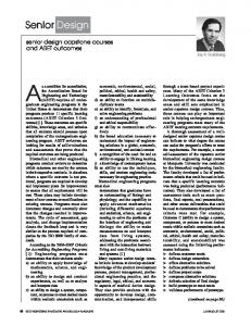
Figure 3.2. The Design Pattern Recovery Environment (DPRE) In the pattern recognition phase, DPRE visualizes the imported class diagram. Indeed, DPRE supports SVG as internal data format, and includes a visualization graph algorithm to visualize the class diagram. Then, design patterns are recovered by using a parser which is integrated in the visual environment. Once the recognition activity is terminated the visual environment shows a report containing the statistics on the recovered design patterns also describing the classes and their role for each recovered pattern. Fig. 3.2 shows a screen-shot of the DPRE during the recovery process for a system implementing a simulator for drive vehicles. In the main window, the environment presents a portion of the class diagram highlighting the recovered patterns. The output window (at the bottom of the figure) shows the description of the recovered patterns (on the left), and a selection item that allows user to select a particular pattern category (on the right). By selecting an entry from this list, the DPRE environment highlights all the classes participating to the instances of the selected pattern. In the example, the parser integrated into DPRE
has recovered 7 adapter patterns, 3 bridge patterns and 5 composite patterns as indicated on the right side of the bottom window. The window visualizing the class diagram highlights the bridge pattern formed by the classes CAirplane, IFlyImpl, CCessna, CSingleEngine, CMultipleEngine. DPRE can also support other reengineering activities since it also includes a UML class diagram editor. Once the UML class diagram has been restructured, the class diagram can be parsed and the corresponding code can be automatically generated in case the original source code was annotated to the class diagram abstracted by reverse engineering. The above forward engineering functionality is not investigated in this paper. The interested reader can refer to [7], [19] for further details. DPRE has been built by using the VLDesk (Visual Language Desk) system [6], a grammar-based visual environment generation system. In the following sections, we focus on the pattern recognition phase by describing how the DPRE has been generated, and the parsing methodology for design pattern recovery.
Proceedings of the Ninth European Conference on Software Maintenance and Reengineering (CSMR’05) 1534-5351/05 $20.00 © 2005 IEEE
4. Grammar-based Design and Generation of Visual Environments DPRE has been automatically generated by VLDesk, a system that inherits and extends to the visual field, concepts and techniques of compiler generation tools like YACC [13]. In fact, VLDesk is based on the formalism of eXtended Positional Grammars (XPGs), which represent a direct extension of context-free string grammars, where more general relations other than concatenation are allowed [5]. The idea behind the definition of such formalism has been to overcome the inefficiency of visual languages parsing algorithms by searching suitable extensions of the well-known LR technique. VLDesk assists the designer in the definition of the syntax and the semantics of the language, and automatically generates a visual environment starting from the supplied language specification. Such an environment encompasses a visual editor and a LR-based compiler. The main components of the VLDesk architecture are: the Symbol Editor, the Visual Production Editor, the Textual Production Editor and the Visual Programming Environment Generator (see Fig. 4.1).
attributes such as attaching regions allow symbols to be connected through links while containment areas allow symbols to be included one into the other. Syntactic attributes are used to relate symbols in a visual sentence. For example, in the UML class diagram in Fig. 4.2 each class symbol (i.e., A, B, and C) has one attaching region as syntactic attribute corresponding to its perimeter, while the aggregation symbol X and the generalization symbol Y have two attaching regions as syntactic attributes corresponding to the two ends of the line. The attaching regions of a symbol are numbered and represented by an array A.regs[1],.., A.reg[n] of sets. The value of A.reg[i] is the set of labels of the links plugged to the attaching region i. Thus, the diagram in Fig. 4.2 can be represented as shown in Table 1, where a specifies the connection relation between attaching region 1 of A and the attaching region 1 of X, b specifies the connection relation between attaching region 2 of X and the attaching region 1 of B, and so on. A
a
X
b
B
c
Y
Visual Language Desk
d
C
Visual Grammar Editor Visual Production Symbol
Editor
Editor
Textual Production
Visual Programming Environment Generator
Table 1. The attribute-based representation of the class diagram in Fig. 4.2
Editor
Visual Programming Environment Visual Editor
Figure 4.2. A sketch of a UML class diagram
LR–based compiler
Figure 4.1. The VLDesk architecture The designer can create the terminal and the non-terminal symbols of the grammar by using the Symbol Editor. Basically, it allows the designer to draw the appearance of the symbols, together with their syntactic attributes and possible visual or textual annotation to be attached (in order to define hierarchical combinations of visual notations). A relation relates symbols through their syntactic attributes. As an example, types of syntactic
Name A B C X Y
A.reg [1] {a,c} {b} {d} {a} {d}
A.reg [2]
{b} {c}
The Visual Production Editor is a visual component supporting the language designer in the specification of an XPG grammar and semantic routines. The designer can further refine it through the Textual Production Editor that allows to define the rules of the grammar together with semantic actions through a text editor. More formally, the language designer specifies an XPG which is a particular type of context-free string attributed grammar (N, TPOS, S, P) where: x N is a finite non-empty set of non-terminal symbols;
Proceedings of the Ninth European Conference on Software Maintenance and Reengineering (CSMR’05) 1534-5351/05 $20.00 © 2005 IEEE
x T is a finite non-empty set of terminal symbols, with NT = ; x POS is a finite set of binary relation identifiers, with POSN= and POST = ; x S N denotes the starting symbol; x P is a finite non-empty set of productions having the following format: A o x1 R1 x2 R2 … xm-1 Rm-1 xm ', * where A is a non-terminal symbol, x1 R1 x2 R2 … xm-1 Rm-1 xm is a linear representation with respect to POS where each xi is a symbol in NT and each Rj is partitioned in two sub-sequences (¢RELj1h1,..,RELjkhk², ¢RELjk+1hk+1,...,RELjnhn²) with 1dkdn. Each RELjihi relates attributes of xj+1 with attributes of xj-hi, with 0dhi