The circuit for F(x0; xn) is shown in Figure 1. 2 Behaviour Transformation for Controllability. To make the large circuit fully controllable, we take all impossible ...
Designing for Testability of Long Pipeline of Modules B. Steinbach, Z. Zhang Freiberg University of Mining and Technology Institute of Computer Science D-09596 Freiberg, Germany email: (steinb/zhang)@informatik.tu-freiberg.de Abstract
In this paper, we propose a method of synthesis for full testability of long pipelined circuits, in which full testability is obtained by changing the behaviour descriptions of each partition using some information about the other blocks of sublogic without changing the global behaviour. The sketch of an algorithm and some experimental results have been included in this paper.
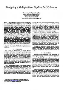
1 Introduction Design for testability has been recognized as a very important objective in logic synthesis in recent years not only because the presence of untestable faults introduce extra hardware into the circuit, but also because that complicates the test pattern generation and simulation. Functional decomposition is a well known method for synthesis of combinational circuits. Steinbach and Stockert proposed a method working directly with the given Boolean function to design fully testable circuits by functional decomposition [1] and get the test pattern parallelly. However, the complexity of functional decomposition grows heavily with the number of variables. Therefore, many design tools are not e�cient for the synthesis of large Boolean functions. In order to cope with this, a method to partition large circuits into parts and synthesize each of the subcircuits independently has been provided in [2]. However, because the logic is partitioned and each of these subcircuits is synthesized independently, the whole circuit designed is probably no longer testable even though each of the subcircuits is testable. To make large circuits fully testable, we proposed recently a method of synthesis for full testability of two level partitioned circuits in [3]. In this paper, we shall extend our results to one class of much larger circuits, long pipelined modules. In the following, we shall give the exact theorems, proofs and the algorithm. Assume F (x0 ; x ) is the behaviour description of the pipelined circuit to be synthesized, F (x0 ; x ) is partitioned into n subfunctions F (x ?1 ; x ) (i = 1; 2; :::; n). Each F is synthesized independently using the methods given in [1]. The circuit for F (x0 ; x ) is shown in Figure 1. n
i
n
i
i
i
n
2 Behaviour Transformation for Controllability To make the large circuit fully controllable, we take all impossible input patterns as don't-cares of the behaviour function of each module F .Theorem 1, bellow, uses the function ' (x ) to enlarge F and tells us that the change of F doesn't change the behaviour of the whole circuit F (x0 ; x ). c i
i
i
i
n
x0
.. .
x1 c(F1 ) ...
x2 c(F2 ) ...
x ?1
x
.. .
c(F ) ...
n
.. .
Figure 1: Circuit for F (x0 ; x ) n
n
n
i
Theorem 1 (Behaviour Transformation for Controllability) Let F 0 (x ?1 ; x ) = F (x ?1 ; x ) _ ' (x ?1 ) i = 2; 3; :::; n ' (x ?1 ) = min (F ?1 _ ' ?1 ) i
i
c i
i
i
i
i
k
c i
i
(2)
c i
i
?2
xi
(1)
i
'1 = 0
(3)
c
then F 0 (x0 ; x ) = F (x0 ; x ) = max n
n
1
x ;:::;x
k
?1
n
f V F (x ?1 ; x )g n
i
=1
i
i
i
Proof: For i = 1 the proof is trivial. We shall prove the cases of i � 2. Without loss of generality, we assume every time only F (x ?1 ; x ) is changed into F 0 (x ?1 ; x ). Let i
F � (x0 ; x ?1 ) = max i
F �� (x ; x ) = i
Then
k
?2
1
x ;:::;xi
n
x
F 0 (x0 ; x ) =
max
i
k
(4)
fF +1 � : : : � F g i
(5)
n
max fF � (x0 ; x ?1 ) � (F (x ?1 ; x ) _ ' ) � F �� (x ; x )g
(6)
max fF � � F � F �� g _ max fF � � ' � F �� g
(7)
x
?1 ;xi
x
?1
k
i
i
i
i
=
i
i
k
n
i
i
fF1 � : : : � F ?1 g
+1 ;:::;xn?1
i
i
c i
i
k
i
;x
i
x
i
?1
i
i
n
c i
;x
i
Solving the recursive functions (2) and (3), we get ' (x ?1 ) = min fF ?1 _ : : : _ F 1 g c i
k
i
(8)
i
?2
0
x ;:::;xi
after conjunction of (8) with both sides of (4) we have F� � ' F� � '
c i
=
c i
� 0
max
k
?2 ;:::;x0
xi
fF1 � : : : � F ?1 � min fF ?1 _ : : : _ F1 gg k
i
(9)
i
?2 ;:::;x0
xi
(10)
combining (10) and (7) we get F 0 (x0 ; x ) = F (x0 ; x ) n
n
Q.E.D.
Theorem 2 (Controllability of F 0) Each input of F 0 is fully controllable from the primary inputs. Therefore, F 0 is fully testable. i
i
The proof of theorem 2 is similar to the proof of theorem 3 in paper [3], we omit it for the sake of briefness. Using the method given in [1], we design the subcircuit c(F 0 ) i
3 Behaviour Transformation for Observability To make the circuit of F fully observable at the outputs of F , we shall change F (x ?1 ; x ) for output x sequentially, so that x can be observed at the primary outputs. i
n
j
i
Theorem 3 (Behaviour Transformation for Observability) Let F 0 (x ?1 ; x ) = [F (x ?1 ; x ) _ ' (x ?1 ; x nx )] i
i
i
i
i
o j;i
i
i
i
i
i
j
i
x
i
i
@ k
x
max
+1 ;:::;xn?1
i
x
when i = 1, 2, � � �, n-1, and ' (x ?1 ; x nx ) = 0 Then F 0 (x0 ; x ) = F (x0 ; x ) o j;n
n
n
n
n
(11)
j
i
' (x ?1 ; x nx ) = maxF (x ?1 ; x ) � min j n o j;i
i
j
j
k
fF +1 � F +2 � ::: � F g i
@x
i
j
n
(12)
Proof: Similar to the assumption in theorem 1, let x? be the j-mirror vector of x , and F 0 (x0 ; x ) = max fF � (x0 ; x ?1 ) � F 0 (x ?1 ; x ) � F �� (x ; x )g (13) j
i
i
k
n
F 0 (x0 ; x ) = F 0 (x0 ; x ) =
i
i
?1 ;xi
xi
(15)
k
?1
i
i
i
?1
x
i
� ' (x ?1 ; x nx ) � i
j
o j;i
i
i
j
i
x
' (x ?1 ; x nx ) i
o j;i
;x
i
j
i
i
@F �� @x j n �� maxF (x ?1 ; x ) � @F @x j [F (x ?1 ; x ) _ F (x ?1 ; x? )] � [F �� (x ; x ) � F �� (x? ; x ) _F �� (x ; x ) � F �� (x? ; x )]
j
o j;i
i
k
i
;x
o j;i
i
' (x ?1 ; x nx ) = maxF (x ?1 ; x ) � min i
n
max fF � � F � F �� g _ max fF � � ' � F �� g
x
Because o j;i
i
(14)
i
?1 ;xi
xi
n
i
max fF � � (F (x ?1 ; x ) _ ' (x ?1 ; x nx )) � F �� g k
n
i
i
x
i
i
i
i
i
x
j
(17)
j
j
i
i
i
(16)
k
i
(18) (19)
j
i
i
n
n
i
j
i
n
n
i
Conjuncting F �� with both sides of (18) we get ' ' '
o j;i
o j;i o j;i
� F �� � [F (x ?1 ; x ) _ F (x ?1 ; x? )] � F �� (x ; x ) � F �� (x? ; x ) � F �� � F (x ?1 ; x ) � F �� (x ; x ) _ F (x ?1 ; x? ) � F �� (x? ; x ) � F �� � maxfF (x ?1 ; x ) � F �� (x ; x )g i
i
xj
i
i
i
i
i
i
j
i
i
i
n
i
i
i
(20) (21) (22)
j
i
i
n
j
i
n
i
j
i
i
n
n
from (22) we have max fF � � ' � F �� g � max fF � � F � F �� g k
?1 ;xi
xi
o j;i
k
(23)
i
?1 ;xi
xi
combining (23) and (15) we get F 0 (x0 ; x ) = F (x0 ; x ). n
n
Q.E.D. Theorem 3 shows that replacing F by F 0 doesn't change the behaviour of F (x0 ; x ). In the following we shall show that by designing F 0 by the method given in [1] the circuit of F 0 is fully testable in the large circuit. Theorem 4 (Observability of F 0) Each F 0 is fully observable from the primary output x . Because ' represents the condition to transfer the error on y to at least one of the primary outputs of vector z, the change of F 0 in theorem 4 guarantees that all test responses of F 0 satisfy this condition and therefore all tests t 0 for F 0 can be used to drive errors in F 0 to the primary output of the circuit of Figure 1. Theorem 4 means that if the subcircuit c(F 0 ) is testable separately, then it is fully testable in the circuit shown in Figure 1. We omit the proof of theorem 4 for the sake of briefness. i
n
i
i
i
i
n
i
o j;i
i
i
i
f
i
i
i
i
4 Design Algorithm And Examples Using theorem 2 and 4 the behaviour descriptions of each module is enlarged. The design procedure is similar to what we have discussed in [3]. We start the design from module n. Then a fully observable and controllable module n is obtained. After that, we design module n ? 1 and get a fully observable and fully controllable module n ? 1. At this moment, we should check if the module n is controllable anymore because of the change of behaviour description of module n ? 1. If module n isn't controllable, we redesign it and get a simpler circuit which is controllable. The design procedure will nish when the rst module is designed. The sketch of our recursive algorithm for synthesis of fully testable pipelined circuits is given in Figure 2. We used the algorithm and designed some circuits. Table 1 gives some results for two level pipeline circuits. We use some benchmark circuits and the extremely redundant example decode-encode with di�erent input width (in which the rst level works as a decoder and the second level works as a coder) to test the number of iterations in our algorithm.
Figure 2: Algorithm Circuit( rst level) misex1 z4ml DCD(4 bits) DCD(5 bits)
Table 1: Test the number of iterations Circuit(second level) number of iteration design time in second misex1 0 2,383 cf2 0 1,7333 CD(4 bits) 4 1,933 CD(5 bits) 5 291,222
5 Conclusion We have shown that when a large logic function is decomposed into pipeline structured subfunctions and each of them synthesized independently, it is possible to get a fully testable circuit by changing these subfunctions properly before synthesizing these smaller circuits. Based on this idea an algorithm has been given. Some examples have been given to test our algorithm. We have focused on design of fully testable large pipelined circuits, we shall discuss more complicated cases in the future.
References [1] Steinbach, B.; Stockert, M.: Design of Fully Testable Circuits by Functional Decomposition and Implicit Test Pattern Generation. 12. IEEE VLSI Test Symposium, pp. 22{27, New Jersey, April 25{28, 1994. [2] Steinbach, B.; Hesse, K.: Design of large digital circuits utilizing functional and structural properties. 2. Workshop Boolesche Probleme, Freiberg (Sachsen), Sept.19{20, 1996. [3] Steinbach, B.; Zhang, Z.: Synthesis for Full Testability of Large Partitioned Combinational Circuits. 2. Workshop Boolesche Probleme, Freiberg (Sachsen), Sept.19{20, 1996.