Jestr
JOURNAL OF
Journal of Engineering Science and Technology Review 6 (3) (2013) 5-9
Engineering Science and Technology Review
Research Article
www.jestr.org
Development of a Mathematical Lumped Parameters Model for the Heat Transfer Performance of a Solar Collector G. Iordanou1 and E. Apostolidou2 1
New and Renewable Energy Group, School of Engineering and Computing Science, Durham University, Durham, U.K. 2
Dept. of Mechanical Engineering, Kavala Institute of Technology, Greece Received 19 December 2012; Accepted 1 October 2011
___________________________________________________________________________________________ Abstract This work describes the developed of a lumped parameter model and demonstrates its practical application. The lumped parameter mathematical model is a useful instrument to be used for rapid determination of design dimensions and operational performance of solar collectors at the designing stage. Such model which incorporates data from relevant Computational Fluid Dynamics design and experimental investigations can provide an acceptable accuracy in predictions and can be used as an effective design tool. A computer algorithm validates the lumped parameter model via a window environment program. Keywords: Lumped parameters mathematical model, flat plate collectors, Solar energy, Enhanced heat transfer, Partial metal porous medium.
__________________________________________________________________________________________ 1. Introduction In the 60’s a method in order to estimate the performance of solar water heaters circulating to a storage tank by thermosyphon was investigated. Two absorber and tank systems were tested and the results compared with those estimated from the theoretical method developed by a computer model. This method incorporated a collector efficiency factor, the solar radiation and the air temperature as a Fourier series in time [1]. In the mid 70’s more comprehensive studies to evaluate the thermal performance of a thermosyphon system were conducted [2, 3]. In the 80’s the long term performance, transient response, system modelling and operation characteristics of a thermosyphon system with vertical or horizontal storage tank were investigated. Its performance was maximised when the daily collector volumetric flow was approximately equal to the daily load flow [4]. A numerical and an experimental investigation of the flow and temperature distribution in a solar collector panel with an absorber consisting of parallel connected horizontal fins were performed. Corrections were determined based on the difference between the measured solar collector fluid outlet temperature and the mean of the measured absorber tube wall temperatures [5]. A similar study described above, was developed using a 3-D mathematical model for solar flat plate collectors based on setting mass and energy balances ______________ * E-mail address:
[email protected] ISSN: 1791-2377 © 2011 Kavala Institute of Technology. All rights reserved.
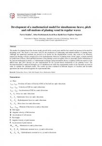
on finite volumes. The model was validated experimentally with a commercial solar water collector. Generally external disturbances that are independent of each other can affect an experimental process. Therefore researchers, while conducting an experiment, do not measure a real value each time but usually observe a random quantity. Hence the mathematical model is made by averaging the measured results [6, 7]. Generally the flow distribution through the collector’s finned tubes clearly affects the operational efficiency of the collector system, Jianhua [8]. Therefore, the more uniform the flow is through the tubes, the efficiency of the collector is higher, and vice versa, Jones and Lior [9]. One passive method that in order to uniform the flow and enhance the heat transfer between the working liquid and the metal part of the collector is the use of a metal porous medium placed in channels of heat exchangers, Nield and Bejan [10], Baytas and Pop [11]. The presence of a metal porous medium (i.e. copper, aluminium) inside a pipe causes a better thermal dispersion and also increases the interface between the fluid and the absorber. 2. Lumped Parameters Model Development The energy conservation equation is the governing equation in the lumped parameter model. Considering Figure 1, the energy of the working fluid entering the pipe at a distance y, plus the useful gain q’u of the tube and fin will be equal to energy gained at distance y+Δy.
G. Iordanou, and E. Apostolidou/ Journal of Engineering Science and Technology Review 6 (3) (2013) 5-9 X
F’= Z+
∑ B +i ·C 2
(4)
i =0
where Z, B, and C are: X -1
∑
Z= 9.45·10 -
Fig. 1. Energy balance on fluid element.
10-4+ i4 ·11.66·10-6
(5)
10-5+ j4 ·11.05·10-7
(6)
i =0
In open literature there is no a general analytical equation for calculation of the collector efficiency factor F’ as function of heat transfer coefficient and the overall heat losses coefficient. This dependence usually presented in the form of tables or charts. The tabulated data from the literature was used to derive a general equation in the form of F’=f (hf, UL). An example of the tabulated data is shown in Table 2a. Combination of three values of the heat transfer coefficient, hfi (100, 300 and 1000 W/m2oC) and the collector overall loss coefficient UL (2, 4 and 8 W/m2oC) were used to derive the general equation that could cover a wide range of flow regimes (laminar and turbulent). Data listed on Table 2a present results taken from Duffie and Beckman. Tab. 2a. Data of h, UL and F’
hf (W/m2C) 100 100 100
UL (W/m2C) 2 4 8
F’ 0.930 0.865 0.765
hf (W/m2C) 300 300 300
UL (W/m2C) 2 4 8
F’ 0.970 0.940 0.890
hf (W/m2C) 1000 1000 1000
UL (W/m2C) 2 4 8
F’ 0.985 0.970 0.945
Y
B= 5.99·10-3 -
∑ j =0
Y
C= 3.4·10-5 -
∑
10-6+ j4 ·1.8·10-8
(7)
j =0
The above equation was checked against charts as shown on Graph 1 below, presented by Duffie and Beckman which display various values of F’ versus tube spacing and various overall heat loss coefficient values UL. It was established that equation (4) can predict the value of F’ without the use of charts. The vertical line indicates that the tube spacing used in the experiments and the theoretical analysis were 11cm apart.
Five new parameters, namely X, Y, Z, B, and C were introduced to be used in the generalised equation: X=7-UL (4)
(1)
Y= (9-hfi)/100
(2)
X and Y refer to the series of values of the heat loss coefficient UL and the heat transfer coefficient hfi, respectively. The collector efficiency factor is given as: 1/ U L
F'= W[
(3)
1 1 1 + + ] U L [ D + (W − D )]F C b πDi h fi
In order to define F’ for wide range of hf and UL values a new generalised equation was introduced in the following form:
Graph. 1. F’ vs. tube spacing for 10mm diameter tubes (hf=1000 W/m2).
3. Validation of the lumped parameter model. A computer algorithm was created using equations 1-9 in order to cross examine the validity of the mathematical model. This algorithm was formed into a window mode program that enables the user to input variables, like the area 6
G. Iordanou, and E. Apostolidou/ Journal of Engineering Science and Technology Review 6 (3) (2013) 5-9
of the collector Ac, the overall heat lose UL etc. The aim of the whole process was to determine the values of F’ and the water output Temperature Tfo of the collector. Using data from Table 2 shown below the values of UL=2 (W/m2C) and hf=1000 (W/m2C) were inputted to the program as shown below on Fig.2. The result obtained is illustrated on Fig.3 where the graph clearly shows that the value of F’ is around to 0.985 similar to Duffie’s findings shown on Table 2a. The computer program created can produce graphs of F’ vs hfi,Tfo vs hfi andTfi vs Tfo.
(8) Combined with data acquired from the literature, were both used to calculate theoretically the temperature of the water in the outlet part of the collector section Tfo using equation (8) in order to cross examine the experimental results to the theoretical techniques employed. Tab. 3a. Data for the conventional and porous collector. Conventional Collector
Porous Collector
W (m)
Variables
0.11
0.11
D (m)
0.01
0.01
S (W/m2)
905
905
UL (W/m2 oC)
6.55
6.55
Tb o C
149.6
148.7
Ta o C
18
18
k (W/m oC)
400
400
d (m)
0.0005
Di (m)
0.008
0.007
m
5.7
5.7
T fi oC
65.6
81.7
Ac (m2)
0.64
0.64
m!
0.62
0.58
4230
4240
(mg/s)
Cp(J/Kg oC)
Fig. 2. Lumped parameter model command window
0.0001
On Table 3a, W is the width of the fin, D is the external diameter of the pipes, S is the solar heat flux, UL is the collector overall loss coefficient, Tb is the base temperature at the joint of fin and tube, Tfref is the fluid reference temperature Tα is the ambient temperature, k is the thermal conductivity of the metal, d is the thickness of the fin. Di is the internal diameter of the pipe, m = U ’ Tfi is the L
kδ
temperature of the working fluid at the inlet, Ac is the area of ! is the volumetric flow rate, and Cp is the the collector, m specific heat of the working fluid. Fig. 4 shows a crosssectional representation of a tube-fin section and points out some of the variables listed on Table 3a.
Fig. 3. Graph of F’ vs hfi
Experimental results obtained during tests in both conventional and the collector with the metallic mesh insertion, were used to validate the developed lumped parameter model. Table 3a illustrates results from experiments (bold data) for the conventional and the porous medium collectors. Fig. 4. Collector fin - tube section.
7
G. Iordanou, and E. Apostolidou/ Journal of Engineering Science and Technology Review 6 (3) (2013) 5-9
The function F which is the standard fin efficiency for straight fins with rectangular profile was obtained from equation (9) for both collectors having a value of 0.974. F=
tanh[m(W − D] / 2] m(W − D) / 2
(9)
For the Conventional Collector: The useful gain q’u for the tube and fin per unit length in the flow direction was calculated using equation (10) for both copper and aluminium finned pipes having a value of 7.29. q'u = [(W − D) F + D][S − U L (Tb − Ta )]
(10)
The thermal resistance to heat flows from the plate to the fluid resulted from the plate-tube bond conductance and the tube-to-fluid convection heat transfer inside of tubes. Reynolds number Re was calculated as: Re =
! 4m πDµ
where Cp is the specific heat of the water, ρ is the density of the water, g is the gravitational force at (55o inclination), β is the thermal expansion coefficient, ΔT is the temperature difference between the outer pipe surface and the water temperature at the pipe wall, L is the characteristic length of the pipe, κ is the thermal conductivity and µ the dynamic viscosity.The average Ra number was obtained for the heat flux of 905 W/m2. The data used to obtain the Rayleigh numbers is listed on Table 3.b. The water properties were taken from charts for the temperatures of 140oC (porous medium collector) and 133oC (conventional collector). Conventional Collector Collector
Porous medium Collector
4270
4286
930
922
Cp (J/Kg oC) 3
ρ (Kg/m )
5.62
g (m/s2)
(11)
β(1/oC) ΔT (oC)
The dynamic viscosity (µ) was taken from charts for ! is the total collector flow rate 133oC. In equation (11) m (0.62ml/sec), D (0.01m) is the diameter of the pipe, µ is the dynamic viscosity (0.209·10-3 Kg/ms). The value of the Re number calculated was 377 which represented a laminar flow (since Reynolds found that for a flow in a pipe it did not matter which of the parameters m! or D varied in this dimensionless group, as long as Re was less than approximately 2300, the flow is laminar) . The collector efficiency factor F’ calculated was 0.873. F’ contains the value of the local heat transfer coefficient h obtained in experiment and equal to 238 W/m2 oC. Finally, the theoretical water outlet temperature was calculated from equation (8) and was equal to 133.4 oC which was very close to the one found in the experiments (133 oC). For the Porous Medium Collector: The useful gain q’u for the tube and fin per unit length in the flow direction was determined for both copper and aluminium finned pipes and was equal to 7.45. Reynolds number Re was calculated for the water temperature of 140oC as found in the experiments. In this ! was 0.58ml/sec, D was 0.01m and µ case the values of m was 0.197·10-3 Kg/ms. The value of Re number calculated was 373 which corresponds to a laminar flow. The collector efficiency factor F’ obtained was 0.885. F’ was calculated for the value of the local heat transfer coefficient h equal to 266 W/m2C (from the experiments). The theoretical output temperature was calculated from equation (8) was 139.5 oC which was very close to the one found in the experiments (140 oC). From the findings so far the average Ra and Nu number for the porous and conventional cases could be obtained over a characteristic pipe length. The average Ra number could be obtained from the expression: Ra =
κµ
L(m) κ(W/m2 oC) µ( Kg/m·sec)
(12)
0.93·10
0.97·10-3
3.0
3.2
0.25
0.25
0.684·10-3
0.683·10-3
0.208·10-3
0.197·10-3
Tab. 3b. Data for the Ra Numbers.
The average Ra Numbers calculated for the convectional collector and for the porous medium collector was 6.35 ·109 and 7.38 ·109 respectively. The average Nu number determined in relation to Ra number for the porous medium case for a heat flux of 905 W/m2 given by the expression (13): 0.285
Nu (905) = 0.0107(Ra )
(13)
The Nu Number obtained for the collector utilising the metallic mesh was 6.91 and for the conventional collector was 5.75. To summarise all the findings, Table 3c was created and illustrates all the results for both collectors. It can be observed that the collector with the metallic insertion material has greater values of F’, Tfout and hf which indicates the enhancement in the heat transfer in the collector. The Nu and Ra Numbers are greater in the case of the porous medium collector supporting the enhancement of the convective heat transfer. The output temperature Tfout, based on the model created by Duffie and Beckman, obtained in both cases from equation (8) is approximately ±0.3oC accurate. Tab. 3c. Porous medium and conventional collector parameters. Variables hf (heat transfer coefficient) F’ (collector efficiency factor) Re (Reynolds number)
C p ρ 2 gβ (ΔT ) L3
5.62 -3
Porous medium Collector 2o
Conventional Collector
266 W/m C
238 W/m2oC
0.885
0.873
373
377
Tfout (output water temperature)
139.5 oC
133.4 oC
Ra Number
7.38·109
6.35·109
Nu Number
6.91
5.75
8
G. Iordanou, and E. Apostolidou/ Journal of Engineering Science and Technology Review 6 (3) (2013) 5-9
4. Conclusion The experimental results validated by the lumped parameter model and demonstrated that can accurately predict the performance of the collector and therefore can be used in the designing process. The computer algorithm also supported these findings. The average Nu number determined and validated in relation to Ra number for the porous medium case for a heat flux of 905 W/m2 given by the expression (13).
A comparison of the findings was made using Table 3b showing clearly the positive effect of the utilisation of the aluminium net inside the pipes of the collector section. A future task would be to incorporate the metallic mesh parameter into the computer algorithm in order to enhance its performance. This application can be used as practical demonstration to students at a Lab exercise.
______________________________ References 1. 2. 3. 4. 5.
CL Gupta, HP Garg. Performance studies on solar air heaters, Solar Energy 11, 25–31. 1967. KS Ong, A finite-difference method to evaluate the thermal performance of a solar water heater Solar Energy 18, 181–191, 1974. KS Ong, An improved computer program for the thermal performance of a solar water heater. Solar Energy 18, 183–191, 1976. G Morrison, JE Braun System modelling and operation characteristics of thermosyphon solar water heaters. Solar Energy 34, 389–405, 1985. J. Fan, L. J. Shah and S. Furbo, Flow distribution in a solar collector panel with horizontally inclined absorber strips. Solar Energy, Vol.81, 1501-1511 2007.
6.
M.Strovanova, L. Takeva, R. Stoykov Testing a flat solar water collector model for reliability Senes-bas, 72 Tsarigradsko chausse, Journal of Chemical Technology and Metallurgy, 41,2, 233-236, 2006. 7. Duffie, J. A. and Beckman, W. A. Solar Engineering of Thermal Processes. John Wiley & Sons, New York, 1991. 8. Jianhua Fan, Louise Jivan Shah, Simon Furbo, Flow distribution in a solar collector panel with horizontally inclined absorber strips, Elsevier Solar Energy 2007. 9. Jones G. F. and Lior, N. L. Flow distribution in manifold solar collectors with negligible buoyancy effects. Solar Energy 52, 1994. 10. Nield, A.D. and Bejan, A. “Convection in Porous Media”, Springer Verlag, N.Y., 1999. 11. Baytas A.C. Pop I. Free convection in a square porous cavity using a thermal non-equilibrium model International Journal of Thermal Sciences, Vol. 41, 2000.
9