established the need for a numerical code needed to couple non-ideal
detonation theory with a valid 3D rock model. • A research group consisting of
engineers ...
Developments Using the Particle Flow Code to Simulate Fragmentation by Condensed Phase Explosives Ruest, Cundall, Guest, Chitombo
BLO-UP Computational kernel of the HSBM Blast Layout Optimization Using PFC3D
Background on the HSBM BLO-UP ↔ PFC3D Interaction Blasthole Definition Detonation Logic Gas Flow Through Fracture Network Stress Waves and Boundaries Material Model Throw Calculation Speed Optimization
•
Spearheaded by De Beers, the HSBM project was developed to marry rockmass characterization data (strength and jointing) with a numerical code to simulate the complete blasting process;
•
Based on his work on the dynamic failure process of kimberlite, Guest established the need for a numerical code needed to couple non-ideal detonation theory with a valid 3D rock model
•
A research group consisting of engineers and scientists from South Africa, the UK, the US and Australia was created to develop the Hybrid Stress Blasting Model (HSBM)
BLO-UP ↔ PFC3D Interaction Unbonded Assembly
Bonded Assembly
BLO-UP ↔ PFC3D Interaction PFC3D is the computational kernel for BLO-UP and BMS
•BLO-UP (and BMS) produces an XML file that is sent to PFC3D •When post-processing, BLO-UP (and BMS) retrieves information from PFC3D for display
PFC3D window
Blasthole Definition •First – Blasthole collar and orientation is defined by the user
•Next - Hole is discretized into finite volumes that contain the total mass of explosive in the hole
mtotal = ∑ mdiscretizations
•Finally – all balls intersected by the cylinder are stored as “loaded” by the appropriate explosive in the deck – volume is conserved by distributing total borehole over all balls
Detonation Logic
Time to detonate for balls is a function of distance from primer and VOD for the explosives
For illustration purposes – balls here are smaller than the standard size in BLOBLO-UP
• Once balls are assigned to the appropriate deck and associated explosive, the blast is initiated at the primer at the user-defined delay
Vixen-n
Unreacted Explosive
Shock Front Sonic Plane (First Pressure Applied to PFC Balls)
DDZ
End of Reaction Zone
Calculated by Vixen-n
Calculated by PFC3D using Vixen-n extent of reaction
Calculated by PFC3D assuming reaction complete λ = 1
Streamline in theory Streamline in PFC3D
Vixen-n Calculate current mass and density
From specific volume, volume and mass, calculate stream tube area
Input At
ρ (t + Δt ) =
MA A(t + Δt ) MA − 2ΔtP&(t ) ρ (t ) A(t )
Calculate current pressure (a function of extent of reaction)
P(t + Δt )
2
1 ⎛⎜ ρ u Du ⎞⎟ D − − TB 2 2 ⎜⎝ ρ (t ) A(t ) ⎟⎠ = ⎛ TA 1 ⎞⎟ ⎜ + ⎜ ρ (t + Δt ) ρ (t + Δt ) ⎟ ⎠ ⎝ 2
Detonation Logic – Calculate Force F=
P A′
A´is the portion of the borehole area assigned to the current particle
F1
F5
F4
F2
F3
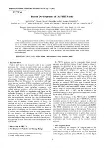
Material Model – Near Field Contacts • Near Field – Before radial hoop stresses, uniaxial strain conditions prevail; – Large stresses cause shear of volumetric yielding followed by volumetric collapse; – Model properties are determined from shock Hugoniot tests as performed at Cambridge University – Cavendish Laboratories and the Sandia National Laboratory
Material Model – Near Field Contacts Experimental results from impact tests on kimberlite (after Willmott et al, 2003) 8.00E+09 Numerical impact tests Longitudinal stress (Pa).
Elastic regime 6.00E+09
4.00E+09
Numerical results from impact tests on sample of “kimberlite”
2.00E+09
0.00E+00 0
100
200
300
400
Particle velocity (m/s)
500
600
700
Slope ->Kimberlite 15 m 5m
->100 mm holes, ANFO ideal -> 3m burden and spacing
20 20 10 0 10
12 m
Results for 40 ms
Gas Flow Logic - Scenarios
Venting to atmosphere mexiting hole
Blasthole draining
Crack flow, intersections and load
Gas Flow P, T and ρ depend on mass, momentum and energy entering or leaving crack
mupstream Μ upstream
mdownstream Μ downstream
ε upstream
ε downstream
mMain Μ Main
ε Main
mdownstream Μ downstream
ε downstream
Reaction Force Force required to re-direct flow
Gas Flow – Macro Cracks
Quiet Boundaries
Used the formulation developed by Lysmer and Kyhlemeyer (1969) “the stress and particle velocity in a plane-travelling wave are related by the acoustic impedance of the medium”
σ = − ρCu& For particles:
F = AρCu&
⎛ Aboundary ⎞ ⎟ ρCu& F p = Ap ⎜ ⎜ ∑A ⎟ p ⎠ ⎝
Velocity (m/s)
Quiet Boundaries
Time (seconds)
Fragmentation Study • • •
Bench – 40ft high Explosive – emulsion, 5 ¾ inch hole, 12 ft. burden, 14 ft. spacing, 43 ft long, 7ft. stemming Delay 4ms, 11ms, 25 ms
Fragmentation Study
“Throw” – Clumping Logic
Conclusions • The paper demonstrates a number of implementations required for simulating the complete blasting process: – Coupled logic between non-ideal detonation code and rock model; – Material model producing realistic crushing and fracturing; – Logic for simulating gas flow from blasthole to the atmosphere; – Viscous “quiet” boundaries; – “Throw logic”;
• Validation is ongoing; • Current computer memory limitations prevent construction of models much larger than 15 m x 7 m x 12 m – limitation removed once compiled for 64 bit processors.
Acknowledgements • The authors acknowledge the contributions from the Sustainable Minerals Institute (SMI) and the Julius Kruttschnitt Research Centre (JKMRC) of the University of Queensland • Generous support of our sponsors: – AEL, Anglo American Base Metals, CODELCO, De Beers, Debswana Diamond Company, Dyno Nobel (AU, US), Placer Dome, Rio Tinto and Sandvic Tamrock
• Many thanks to Martin Braithwaite and Claude Cunningham for the help in coupling Vixen-n and BLO-UP • Special thanks to the project reviewers: John Field, Finn Ouchterlony and Martin Braithwaite • We would like to recognize the vision of De Beers in developing and leading the HSBM project.