track system using equations advanced by Kerr 1° for a beam. The results ... portion of the crib-ballast underneath the rail section carries a significant amount of ...
Dynamic models of a railroad track system B. Prasad a n d V. K. G a r g Dynamic Research Division, Association o f American Railroads, 3140 South Federal Street, Chicago, lllhlois 60616, USA (Received 22 January 1979)
A continuum model with microstructure is presented for a railroad track system. The track is represented as a laminated structure with two layers continuously supported by springs and dampers. The differential equations advanced b y Sun 24 for a composite system are used in the formulation. Solutions for deflections of the track system subjected to a moving wheel load are obtained in a close form using complex Fourier transforms for both damped and undamped foundations. Comparisons are made with the results obtained from quasi-static models of the track, which simulate the track as a single equivalent homogeneous beam on an elastic foundation with an effective modulus suggested by Voigt. 31 Results of the model are compared with experimental data in limiting cases. Critical velocities are calculated for the track system with conventional rails. The influence of foundation modulus on critical velocity is analysed in some detail. Critical velocities are also computed for an equivalent homogeneous track system using equations advanced by Kerr 1° for a beam. The results of this study agree quite well with those obtained using the continuum model with microstructure. Introduction The response of railroad tracks to moving loads has been investigated by various authors in the past. 4,16-17 Many models 21,3° have been proposed to predict the track response due to a moving (constant or fluctuating) load 16-17 An early investigation was performed by" Timoshenko 3° to calculate the dynamic stresses and deflections of a rail under the action of the moving wheel loads o f a locomotive. In the analysis, the track was replaced by an elastic beam supported on a Winkler-type foundation. Subsequently, many investigators carried out studies for the Euler-Bernoulli and Timoshenko beams placed on elastic foundations and subjected to moving loads. 1,3,9,22,23 In recent years, with the introduction of welded railroad track, considerable attention has been given to determining the effect of axial forces on critical velocitiesof the track, s,1° The response of an axially stressed infinite track without damping due to a moving load with constant velocity has been considered by Kerr. 1° Dokainish s has analysed a similar case by including the effect of damping. Both the Euler-Bernoulli and Timoshenko beam models of a track structure do not account for load carrying 0307-904x/79/050359-08]$02.00 © 1979 IPC Business Press Ltd
capacity and the inertia effect of ties and ballast which are present in the system. It has been noticed 11,14 that the portion of the crib-ballast underneath the rail section carries a significant amount of the vertical load. Ties also share the load partially tkrough bending and partially in direct compression. The primary layer of ttie ballast is, however, nonhomogeneous and granular in nature. Earlier investigatorslO, 12,13,21 have neglected the effect of ties and ballast while considering a single running rail infinitely. It has been feltn, 14 that the layer consisting of ties and the alternating layers of crib-ballast fillers underneath the rail Cannot be neglected because they elastically support the toad and contribute to the inertia. Their inclusion in the analysis requires a significant detail in modelling. 26 A static model based on the finite element method has been developed recentlyfl 6 The model accounts for the ties and treats the primary ballast as the elastic materials underneath the rails. Stress-dependent material properties of the ballast, the sub-ballast and the subgrade obtained from triaxial tests are used in the model. A good agreement has been reported between the measured response at Section 9 of the Kansas Test Track 27 and that calculated using the finite element modelfl 6 No dynamic model
Appl. Math. Modelling, 1979, Vol 3, October
359
Dynamic models of a railroad track system: B. Prasad and V. K. Garg
(either analytical or based on the finite element discretization) has been developed so far which includes the ties and ballast fillers and is subject to a constant moving wheel load. Previous attempts have been limited to an analyses of the rail as an infinite beam subjected to a moving or fluctuating load.9, m, 12, ~3 It is well known that homogeneity is not an absolute clmracteristic of matter, but is a term used relative to the scale of interest. When viewed on a sufficiently large scale, a heterogeneous medium can be considered as grossly homogeneous. 24 This has been the fundamental idea upon which classical continuum mechanics is based. The classical theory becomes inadequate when the characteristic length of deformation (wave length) is comparable to tile sizes of the inhomogeneities, e.g. the grains of a granular material or the fibres in a fibrous composite. In recent years, following the work o f Mindlin Is and Eringen 6 much effort has been made to develop a new microcontinuum mechanics, which takes into account the intrinsic motions of the microelements. In many heterogeneous materials, for example, the engineering composites, the material properties as well as the geometrical layout of the constituents, are known. It thus appears to be desirable if the gross material properties can be derived from those of the constituents. With the foregoing in mind, several continuum theories 2,24,2s have been proposed for a laminated medium. These theories 2,24,2s involve a smaller number of material constants and are simpler to use. In 1961, Filippov 7 suggested a three-dimensional elastic half-space model for the track foundation in which the inertia effect of the ties was included but the bending rigidity was ignored. He solved the problem of an infinite beam resting on an elastic continuum subjected to a concentrated load. Labra 1 2 - ° extended this work to study tile effect of an axial force, lie considered the track as an axially stressed elastic beam resting on an elastic half-space with inertia and subjected to a moving load of constant velocity. The dynamic response of a composite or laminated structure subjected to a moving load has recently been analysed by Sve 26 using the continuum theory for a laminated medium 2s and by Prasad 28 using tile microstructure theory of a composite beam. 24 In Prasad, 18 dynamic response of a damped composite beam consisting of a large number of parallel alternating plane layers of two homogeneous, isotropic elastic materials has been considered. In this study the microstructure theory has been applied to study the response of a railroad'track system subject to a moving wheel load. The effect of tie spacing, foundation modulus, and damping on the critical velocity of a track system are analysed in some detail.
a Tie spacing
b
Ties
.
Rail
S°?
4ft 8-1/2in(~435cm)-~
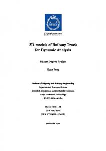
~7//Z,%,'g///~'x\v.///a',\v4///,,%,\'¢d///ZSu b g ra d e"///Ax\\'K///xq,\\"~///~\v,///,,%,\'g//2 Figure ! Typical sections of a conventional railway track. (a), longitudinal section; (b), transverse section
an elastic half-space and supports tile rails and the ties. The materials under the rails and in between tile ties deform as the rail deform due to moving wheel loads n,14 and as such they act together like a second infinite elastic layer. In the present analysis, because of symmetry, only half of the track structure with a single rail is considered. The track system is assumed as a two-layered structure placed on an elastic foundation and subjected to a moving wheel load. The first layer is constituted by the original rail section. The second layer replaces tile ties and crib-ballast fillers (Figure la), laid alternatively in the longitudinal direction of the track, by a layer of homogeneous material with equivalent moduli and mass density. The gross properties of tile equivalent homogeneous layer can be established in terms of its constituents. Two basic theories w,31 have been proposed. Tile first contribution was made by Voigt 31 who assumed that when a polycrystalline specimen is subjected to a gross uniform strain, the crystals would be in the same state of applied uniform strain. Reuss 19 used a similar approach and assumed that all the crystals would be in the same state of uniform stress. For the track structure system considered here, the Voigt 31 model appears to be more appropriate and has been used in the present analysis. For the composite medium with two materials namely tie (El, Gt, vt) and crib-ballast filler (E/-, Gf, v.t-) distributed evenly along the longitudinal direction, the effective elastic and shear modulus of the equivalent micro elastic layer of material are written on the basis of Voigt 3~ as:
Description of track model
E 2 = UlEt + f b ( l --/al)E.t-
The railroad track structure (Figure 1) usually consists of two parallel steel rails, wooden cross ties and several layers of coarse granular ballast materials all resting on the parent soil subgrade. Ballast is filled in and brought up flush with the rail bottom in between the tie spacingL Tile space occupied by crib-ballast (Figure la) between any two adjacent ties varies from 12 to 14in (30.48 to 35.56 cm). A typical rail flange width measures about 3 to 4 in (7.62 to 10.16 cm) and the tie-depth usually varies from 7 to 8 in (17.78 to 20.32 cm). In service conditions, the space (3in x 12 in x 7 in) is fifily packed and compressed with the ballast materials. The media below the ties base acts like
G 2 = IA1G t +fb(1 -- lal)Gf
360 Appl. Math. Modelling, 1979, Vol 3, October
Crib-ballast
(1)
where gl = twits; tw and t s denote the width and spacing of ties. fb is the fraction of ballasting (0 < f b < l);fb = 1, corresponds to a case when the crib-ballast are fully packed in between the cross-ties and underneath the rail;f b = 0 represents no ballasting. The effective mass density of the equivalent layer is similarly established as: P2 = P,/'ll + f b ( 1 -- Idl)Pf where Pr and p/- are the mass densities of tic and cribballast, respectively. The equations similar to (1) and
(2)
Dynamic models of a railroad track system: B. Prasad and V. K. Gary (2), have also been used by Sun 24 for comparing dispersion curves for flexural waves of a laminated composite with microstructure and in Prasad 18 for comparing the dynamic response of a laminated beam due to a moving load. The track model, therefore, consists of a layer of rail (El, GI, vl) and an equivalent layer underneath the rail (E2, G2, v2) replacing the ties and crib-ballast filler which are laid alternatively in the longitudinal direction (Figure Ia). The structural damping of the rail, the cushioning effect of ties and the airgaps between the ties, ballast sub-ballast and subgrade are simulated by the Winkler type foundation consisting of springs placed parallel to dashpots. The differential equations proposed by Sun 24 for a laminated system are modified for the track structure system characterized by equations (1) and (2) to analyse its dynamic response when subjected to a moving wheel load and placed on an elastic foundation with and without damping. The analytical formulation is presented in the following section.
( a , - a 4 v2) d2w _ _ dr 2
a2w -
a 2 -
Ox
a¢ -
a3
--
OX
aw 02~ a2 ~xx + a5 -Ox - 2 -a6~t-
p + -
~
dw a3
a 4
--
=
_
(7)
( a 7 _ a l o V 2 ) d2~ - dr 2
_
+
=
as¢
0
(8)
a8l]/
+
dr----~ - al2~b = 0
(9)
Tile above differential equations are in tile moving reference frame (r,y, z). r is the distance measured from the point of application of the moving load. Introducing the non-dimensional variables: II7 =
e=
r
-rl
R
Fo
=-
V0 =
N/~2/P2
F*
-
rI
kr~
/3-
al~
floQ Vo
ai $
Pl X =P2
Gl F=-G2
2~a
dI h r/--} - - dl +d2 dl + d 2
al
- -
Ot2
a5
2=a,r
a I
(3)
a,
(lO)
a7
all
a?
all
n3-ald
al3
' 2 Ot
Ow - ~t -
a 5
a4v2 a2
(11)
a4v~ %
alev02 e 4 = a , 3 ~
(12)
simplification can be achieved. Tile solution may now be constructed with the use of Fourier transforms. The following pair is used: (4)
co
~(s)
= j ,(n)
e -i'n
Itg
(13)
oo
02~
m -i)t- 2 +
F°6(x-vt)-kw-(3°
1 _
and tile nondimensional constants:
if
u(R) = - 2n
(5)
where w is the transverse displacement, ~ is the local rotation of the stiff layer and ff isZthe gross rotation; al, a2, . . . , a n are the constants which depend upon material and geometrical configurations of the composite beam and are defined in Sun. 24 If a load of constant magnitude F 0 moves with constant velocity v over the track, which is supported by springs placed parallel to dashpots, the quantity p in equation (3) becomes: p(x,t)
_
dr
v 0=-Vo
02~ a7 -Ox - 2 +a8~5
a2~ _ a
d(ib dr
--
÷ ( a , l - a 1 3 v2) d2~b
02~ 02~ a7 Ox2 + a s ~ + all OX2 --al2~b
=
a 3
02w =
02~ 02~ = a9 --- alO ~ 0t 2 at 2 aw a3 Ox
_
(a 7 --alov 2) d25 - dr 2
-
w
O~p
- 8x 2
- -
dw d2~ a 2 - - + (a 5 - a 9 v2) - __ a6~ dr dr 2
This section describes the analytical formulations for two models of the track support system. The first model is based on the microstructure theory and considers the track as a two-layered laminated system Whereas the other model is derived from an equivalent modulus theory.
al
d~ dr
a 2
( dw'~_ F 0 5(r) x kw-flo v dr/ - -'-~
Analytical formulation
Microstrttctttre theory The microstructure theory for a laminated system proposed by Sun 24 yields a system of partial differential equations of motion in three dependent variables w, 4~ and $ as:
_
(6)
where s is a Fourier transform parameter. 1700 .~16OO
I "~
j
~
~
,
~
.
~
"" ~
~
zz~ 15OO
>- 14oo S13oo
~> 12oo
~11oo '
,
,
,
,
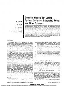
15OO 2 0 0 0 2500 3000 Foundation rnodutus, (Ib/in 2} Figure 2 Effect of foundation modulus on critical velocity. 115 AREA rail section. ( ), laminated track model; (----), equivalent beam model based on Kerr's formulae 1OO OO
where k is the equivalent spring constant, fl0 is the damping coefficient. Stipulating a steady-state solution with r = x - vt, equations ( 3 - 5 ) can be rearranged as:
t~(s) e isR ds
1OOO
Appl. Math. Modelling, 1979, Vol 3, October
361
Dynamic models o f a railroad track system: B. Prasad and V. K. Garg
Assuming that dependent variables and their derivatives approach zero at infinity, the equations ( 7 - 9 ) transform to:
174(1 --02/0t4) + 2/'/3(171 --1)(1 -- 0%3 ) or 172(171 1)2( 1 02/a2) - -
D
[(a~ - a4v 2) s 2
a2is
p3 =
a3is
isr 1 + kr~] -floV ~ ~J
P4 =
-
(21)
17J(1 - ~) -- l
171 [,72174(1 - o % 2 ) ( I - 0 % , 0 -,7](1 - o ] / m ) 2] 17,/0 - 17) -- 1 (22)
a2is
as + (aT
- I n 6 + (as
1/1174( 1 -- 02[0:4) + 171173(171 -- 1)(1 -- 02/cx3) p5 =
-- a9V2) ~1~ ]
--aloV2)r@] P6 =
a3is
-/a,2+(ml ~]
~8 + (aT
- a,3v 2)
Fo[~
0
(14)
m/(1
171172(171- 1)(1 --02[ot2) + 171173(1 --02[°t3)
The nondimensional constants 17i, ei, for i = 1, . . . , 4 defined in expressions ( 1 1 - 1 2 ) can also be expressed in terms of geometrical and material properties of tile laminated model of the railroad track. The independent parameters are %/3 and 0. Tlie denominator A of equations (15--I 7) is a sixthorder polynomial in s with real and imaginary coefficients. Once the roots of the characteristic equation, A = 0, are deternfined, the transformed functions W--(s),fJ(s) and ¢(s) can be expanded into partial fractions; each term of which can be set in a general form of the type A[(s + a + ib) where A is a constant, - ( a + ib) is a root in which a and b can be positive, negative or even zero. The inverse transform of W(s), ~(s) and qT(s) can be accomplished by recalling that: I
= - s g n ( b ) i ebRe -iaRH [-R sgn(b)]
s+a+ib
where W, ¢ and ff are the transformed variables. After simplification of (14) we obtain:
= -
F*(sap4 + s2p2 + 1)
and:
H[R] Os)
A F*is(s2ps + 1)
(16)
A
F*is(s2P6 + 1)
(17)
A where:
F* = Fo[a l ~ and
A = (s2Pl -- 2flOis+a)(s4p4 +s2p2 or l) S2(s2p3 or 1) -
-
02/~1) 174(I --02/0~4) -- 172(17"/'/1-- 21"/--171 or 1)
P2 =
-
x (1 -- 0 % 2 ) -- 2r/173(1 -- 02/a3) 1
362
-
-
( l -- 17)/171
A p p l . Math. M o d e l l i n g , 1979, V o l 3, O c t o b e r
=
1 forb >0 - 1 for b < 0
(25b)
1 forR >0 0 forR