N. Anantrasirichai, C. Nishan Canagarajah , David W. Redmill and David R. Bull. Department ..... Peter N. Belhumeur, David Mumford, âA Bayesian Treatment of.
DYNAMIC PROGRAMMING FOR MULTI-VIEW DISPARITY/DEPTH ESTIMATION N. Anantrasirichai, C. Nishan Canagarajah , David W. Redmill and David R. Bull Department of Electrical & Electronic Engineering, University of Bristol, Bristol BS8 1UB UK
ABSTRACT A novel algorithm for disparity/depth estimation from multiview images is presented. A dynamic programming approach with window-based correlation and a novel cost function is proposed.. The smoothness of disparity/depth map is embedded in dynamic programming approach, whilst the window-based correlation increases reliability. The enhancement methods are included, i.e. adaptive window size and shiftable window are used to increase reliability in homogenous areas and to increase sharpness at object boundaries. First, the algorithms estimates depth maps along a single camera axis. The algorithsm exploits then combines the depth estimates from different axis to derive a suitable depth map for multi-view images. The proposed scheme outperforms existing approaches in parallel and in the non-parallel camera configurations.
1. INTRODUCTION The disparity/depth estimation algorithm from the sequences of stereo/multi-view images is an important element in 3D vision. Owing to occlusions, imperfect camera calibrations, imperfect light balance and homogenous colour/luminance, the accurate estimate of disparity/depth remains a challenging problem. In this paper, we use dynamic programming to determine the optimal disparity/depth fields, which was first introduced in [1] for stereo images. The dynamic programming approach is better than traditional matching schemes, since it does not contain blocking artefacts or noisy depth maps. Moreover, the dynamic programming is efficient to solve multi-stage problems, which enables disparity estimation and occlusion detection simultaneously. The choice of a good cost functions for searching the minimum-cost path is a key aspect of the dynamic programming approach. The simplest cost function utilizes the similarity of luminance between the left and the right views. I. Cox has proposed the matching process using individual pixel intensity [2]. Although cohesivity constraints are used to deal with the inter-scanlines disparity discontinuities, the ambiguity from imperfect light balance might affect homogenous areas. Therefore, we investigate the performance of the window-based correlation for dynamic programming and propose some enhancements such as adaptive window size and shiftable windows. The small window size and shiftable windows lead to
sharp object boundaries, whilst the large window size achieves better matching in homogeneous areas [3]. The dynamic programming scheme can be improved by supplementing the cost function to identify the occlusion. The accuracy of the occlusion detection has been enhanced by Bayesian method which requires a probability of occlusion [4,5]. N. Grammalidis and M. G. Strinzis have proposed the disparity estimation and the occlusion detection algorithm for multi-view system by using dynamic programming, but cost defined to identify occlusion is fixed [6]. In this paper, we propose a simple but effective cost function by exploiting confidence information from other cameras. The erroneous prediction by using one view reference is avoided by exploiting the other reference views. This produces better disparity estimation by using multiple reference views. The proposed scheme is tested with the parallel and nonparallel camera configurations. Each configuration is considered with two types of camera geometries: a linear case (one dimension) and a planar case (two dimensions). In the later case, a joint horizontal and vertical scanning is proposed to deal with the multiple global minima. The rest of paper is organized as follows: Section 2 describes the proposed cost functions. Then, Section 3 explains the window-based correlation with adaptive window size and shiftable window. The performance of the proposed scheme is tested with two camera configurations and results are presented in Section 4 with conclusions in Section 5. 2. PROPOSED COST FUNCTIONS FOR DYNAMIC
PROGRAMMING We propose to search the matching pixels along each scanline through dynamic programming and the disparity/depth of each pixel comes from the optimum path. Considering one particular pixel, there are three possible disparity values, which are equal to, more or less than that of the consecutive pixel. The first case usually occurs in the non-occlusion areas, whilst the last two cases possibly occur in the half-occlusion areas. Hence, three costs are defined to each node (i, j) in dynamic programming; C1 and C2 are the occlusion costs of the pixel, which are invisible in left view and right view respectively, and C3 is the cost of the pixel in non-occlusion areas. These costs are expressed as follows: 1 1 C1 = − El + Er , C 2 = − Er + El λ λ
, C 3 = El + E r
(1)
El
where
=
B R1 d) B L1 , Er = 2 1 + λ ⋅ e ij (d ) B R1 1 + λ ⋅ eij2 ( L d ) B1 C R 2 e ij (k ) = ∑ a iˆˆj ⋅ ( p ˆˆ − p ( iˆ )( ˆj +k ) ) 2 , a iˆˆj e ij2 (
eij2 (d )
( iˆ , ˆj )∈wij
ij
(2) is a weighing
coefficient that is inversely proportional to the distance from the pixel (i,j), and pij is the intensity of pixel pixel (i,j). The L1
R1
B and B are the baseline between the current camera and the closest left and the closest right cameras respectively, whilst λ is the occlusion parameter. The occlusion parameter directly affects the costs in dynamic programming. The appropriate value depends upon the details of images, i.e. the multi-view image sequences composed of a wide range of depths require a large λ for operating and vice versa. The areas where the depth is changing usually contain the high different luminance from the reference view at the same position, so an initial λ is determined as follows. For each pixel (i,j), the energy of different luminance between the current and the reference view, e 2ij (0) , is computed.
Then, the value 1 λ , which is the intersection of function E and (1 λ − E ) , is defined to be an energy threshold that half the number of pixels of an image have the energy e 2ij (0) less than
cost (i − 1, j − 1) + C 3 ) path(i, j ) = arg min cost (i, j ) d
2.1 Multi-view image extension To extend the three-view disparity estimation to the general multi-view disparity estimation for a linear configuration, the error from all the reference views are compared and the minimum is selected. The error function becomes:
El
Er
e2 (d ) , = min 1 + λ ⋅ e2 (d )
B R1 e2 ( L d ) B1 = min R1 2 B 1+ λ ⋅e ( L B1
B Ln B L2 e2 ( L d ) d) 1 B B L1 , ... , L2 Ln 2 B 2 B 1+ λ ⋅e ( L d) 1+ λ ⋅e ( L d) 1 1 B B
e2 (
B Rm B R2 e2 ( L d ) d) L1 1 B B , , ... , R2 Rm 2 B 2 B d ) 1+ λ ⋅e ( L d ) 1 + λ ⋅ e ( L1 d ) 1 B B
(5)
e2 (
(6)
(3)
where B Lx and B Rx are the baselines between the current camera and the xth camera on the left and right sides with total n left view references and m right view references respectively. Better prediction is achieved by exploiting the information from other view references. However, these error functions are adapted to the cost C3 only, whilst the cost C1 and C2 are still calculated from the closest left and the closest right views. This is because the smaller error might lead the mistaken path in occlusion areas, i.e. C3 would dominate instead of C1 or C2.
(4)
2.2 Combining horizontal and vertical scanning
1 λ . We suggest that the experiments would run with the λ values near the initial one to find the best result. The accumulated cost of each node (i, j) is marked as in Eq.3 and the selected path of each node is in Eq.4.
cost (i, j ) = min(cost (i − 1, j ) + C1 , cost (i , j − 1) + C 2 , ...
areas composed of similar details of the neighbouring nonocclusion areas. However, if more cameras are available, this problem could be eliminated by using other reference views. The following subsection 2.1 and 2.2 show the proposed schemes for more than three cameras that are available in a linear case and a planar case respectively.
Finally, the least accumulated cost of the last pixel in a scanline is selected to identify the optimum path. After tracking back along the optimum path, the estimated disparities are generated and the occlusion areas are simultaneously marked at the pixels where the occlusion cost dominates. The proposed algorithm achieves the disparity estimation and occlusion detection by exploiting the error of the intensity/colour matching. The large e 2 ( d ) value implies occlusion that the current pixel could not match any pixel in the reference view. This situation always occurs near the object boundaries that the disparity of this pixel is different from those of neighbouring pixels. Therefore, it can be marked that this pixel is located in the background of the current view and it is occluded by foreground in the reference view. That is, if C1 or C2 dominates, this pixel is in the background and the disparity is decreasing or increasing respectively, but if C3 dominates, this pixel could be either in the background or the foreground with the same disparity as the previous pixel. For example, a large El and a small Er cause the value of C1 less than C2 and C3, therefore C1 dominates, i.e. this current pixel does not correspond to any pixel of the left view reference but evidently match one pixel in the right view reference. Hence, this pixel is in the background on the right of the foreground object. Noticeably, the incorrect path might appear at the occlusion
If the image sequences are available both vertical and horizontal direction, the estimated disparity from scanning in one camera axis could be used to modify the cost for each node of scanning process in another camera axis by pre-marking the occlusion areas. After vertical scanning, for example, the possible occlusion regions of the horizontal scanning are marked from the vertically estimated disparity map, and then the costs C1 and C2 of such regions are adjusted with the proportion α as follows: C1
1 = α ⋅ − El λ
+ Er
,
C2
1 = α ⋅ − Er + El λ
(7)
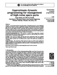
where 0 < α < 1. As a result, the disparity and occlusion in this horizontal scanning are more reliable than that does not exploit information from the vertical scanning. Then, the result of the vertical scanning where C3 dominates is used to replace the result of the horizontal scanning which is marked as occlusions. This could compensate the faults of the one-directional scanning which come from the continuity of the tracked path when the disparity of this area is dropping from the foreground or come from the too narrow gap between the front objects as shown in Fig. 1 at A and B points respectively. In conclusion, to increase the reliability, we also propose to use the result of the first scanning if C3s of these areas dominate to replace the result of the second scanning in the occlusion area.
Firstly, the proposed scheme is applied to the parallel camera configuration, then to non-parallel camera configuration. 4.1. Parallel Camera Configuration A
B
Considering the parallel camera configuration, which is the simplest formation of multi-cameras, the camera axis is not rotated from each other, as well as the world coordinates. If the image point x 1 is normalized, the space point’s coordinates are X w = Z w K −1 x 1 = x 1 + K t / Z w . If the disparity, d1→2 , is defined as
Fig. 1 The disparity estimation with the thick solid line showing the tracked path of the optimum global cost, and the thin solid line showing the estimated disparity got from the tracked path. Some mistakes possibly appear as the difference from the true disparity (dotted line).
3. WINDOW-BASED CORRELATION AND ENHANCEMENT SCHEMES The window-based correlation is investigated in this paper. The cost of each node is found by exploiting the correlation of the current pixel and its neighbourhoods. The details in a window gain more reliable matching compared to a single pixel. Moreover, the performance of the window-based correlation can be improved by exploiting variable window sizes and shiftable windows method. The purpose of the adaptive window size scheme is to solve the error matching in the homogenous region. This lies in the basic idea that the higher variance gains the higher perceived reliability. Hence, the window size is grown to cover enough details of the texture, but not too big to make the depth inhomogeneous in a window. In this paper, an adaptive window or block size is chosen based on the following approach. Firstly, each pixel starts with 3x3 window size. Then, if there is no edge inside, the size is increased to be 5x5 pixels. On the contrary, the size of the window that includes the edge details will be decreased to 2x2, if the variance of the window is more than the specific threshold. The results will be shown in the next section. For the shiftable windows, this algorithm improves the matching areas near the object boundaries that produce the depth discontinuities. The window of the conventional approach is centred at the current pixel, whilst the shiftable window could be located at the appropriate area that minimizes the overlap region. The proper window position might be defined by various criteria. The minimum sum of the absolute difference (SAD) is one of the simple criteria. It is assumed that the homogenous luminance regions contain the homogenous depth. The minimum SAD between the matching windows located at the homogenous depth is less than the minimum SAD between the matching windows located at the area composed of various depths. 4. DISPARITY/DEPTH ESTIMATION FOR MULTIVIEW IMAGE SYSTEM The proposed algorithm exploits the property of multi-view points and possible occlusions to indicate the constant or transition stage of disparity/depth. This section shows the results of the proposed scheme described in previous sections.
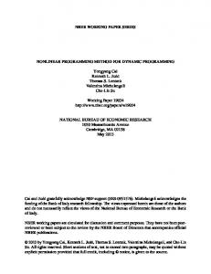
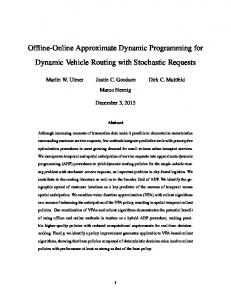
the vector from a point in image 1 to its corresponding point in image 2, the depth Z w has a relationship with the disparity d1→2 = −K t / Z w . Additionally, if the translation parameters are reduced to only one direction, the disparity can be rewritten to d1→2 = − f B12 / Z w , where f and B12 represent the focus length and the baseline between camera 1 and camera 2 respectively. It implies that only the disparity or the shift distance between the corresponding pixels is adequate to represent the 3D information. Therefore, the disparity estimation scheme is proposed for this simple geometry instead of the depth estimation The Head sequence is employed to simulate the proposed scheme explained in section 3 and 4. The estimated disparity map of the traditional fix window size is illustrated in Fig. 2 (c), whilst the results of the enhanced variable window size scheme is shown in Fig. 2 (d) that is the result of three window sizes as the algorithm described in section 3. Then, the shiftable window approach was tested with fix window size. The estimated disparity map is significantly improved as shown in Fig. 2 (e). Fig. 2 (f) displays the estimated disparity from the vertical scanning by applying both adaptive window size and the shiftable window. Subsequently the predicted occlusion areas for the horizontal scanning, shown in Fig. 2 (g), are marked by the result in Fig. 2 (f). Finally, the disparity field estimated by congregating the horizontal and the vertical scanning as explained in section 3 is illustrated in Fig. 2 (h). 4.2. Non-Parallel Camera Configuration The disparity of this system is not just the one directional shifting, along neither horizontal nor vertical axis. However, searching the corresponding points among views can be minimized to one direction along the epipolar line. The epipolar line, Ev, in view v ( v ∈ {l : left view , r : right view } ) that corresponds to the normalized pixel x m = (i, j, 1) T of the middle view m can be calculated by E v = Fv x m [7], where Fv is the fundamental matrix of view v corresponding to the middle view. Fig. 3 (a) illustrates the original image of Leo1 sequence in the middle view; whilst Fig. 3 (b) and (c) shows the estimated depth map with precision of 0.0076. This 480x270-size sequence is composed of 5 views in the horizontal direction and 3 views in the vertical direction with the non-parallel geometry. From Fig. 3 (b), the result of dynamic programming without any enhance scheme shows the performance of proposed cost 1
The multi-view Leo sequence was captured at University of Bristol
(a)
(b)
(c)
(d)
(e)
(f)
(g)
(h)
Fig. 2. (a) The middle view of the original image. (b) The true disparity. The horizontally estimated disparity map of Head multi-view images with (c) no any enhanced scheme. (d) variable window size but not shiftable window. (e) shiftable window (SAD) but not variable window size. (f) The vertically estimated disparity map with variable window size and shiftable window. (g) The occlusion map. The black and grey colours indicate the area that might be occluded in Left view reference and Right view reference respectively, whilst the white colour shows areas that could be seen in all views. (h) The estimated disparity map with vertical and horizontal combination.
(a)
(b)
(c)
Fig. 3. The middle view of the Leo multi-view test images. (a) Original images. (b) Estimated depth map by dynamic programming without any enhance scheme. (c) Estimated depth map by dynamic programming with adaptive window size and shiftable window and also exploiting vertical and horizontal congregation.
Functions for non-parallel geometry, and the result is greatly improved when the adaptive window size, the shiftable window and the combination of vertical and horizontal scanning method are included as shown in Fig. 3 (c). 5. CONCLUSION In this paper, a novel disparity/depth estimation based on window-based dynamic programming is presented and the cost functions to take into account discontinuity and occlusion are defined. The adaptive window size and shiftable window are included to improve the reliability and sharpness. According to the result, the proposed method provides more realistic disparity/depth map for all camera configurations. Moreover, the proposed horizontal and vertical scanning combination can highly improve the estimated disparity/depth map, if the twodimensional array of multi-view camera allocation is available. 7. REFERENCES 1. Y. Ohta and T. Kanade, “Stereo by Intra- and Inter-Scanline
2.
3.
4.
5.
6.
7.
Search Using Dynamic Programming," IEEE Trans. Pattern Anal. and Mach. Intell., vol. 7, March 1985, pp. 139-154. I. Cox, “A maximum likelihood N-Camera stereo algorithm,” Proceedings of IEEE Conference on Computer Vision and Pattern Recognition, 1994, pp. 733-739. T. Kanade , M. Okutomi, “A stereo matching algorithm with an adaptive window: theory and experiment,” IEEE Trans. on Pattern Anal. and Mach. Intell.,1994, pp. 920 – 932. I. Cox, S. Hingorani, and S. Rao, “A Maximum Likelihood Stereo Algorithm,” Computer Vision and Image Understanding, Vol. 63, No. 3, May 1996, pp. 542–567. Peter N. Belhumeur, David Mumford, “A Bayesian Treatment of the Stereo Correspondence Problem Using Half-Occluded Regions,” Proceedings of CVPR '92, 15-18 June 1992, pp. 506 – 512. N. Grammalidis and M. Strintzis, “Disparity and Occlusion Estimation in Multiocular Systems and Their Coding for the Communication of Multiview Image Sequences,” IEEE Trans. on Circuits and System for Video Technology, Vol.8, No.3, Jun 1998, pp. 328-344. R. Hartley and A. Zisserman, "Multiple View Geometry in Computer Vision," 2nd edition, Cambridge University Press, 2004.