Performance Computing clusters due to high bandwidth and low latency that ... hosting one or more CPUs or memory modules, and I/O devices hosting disks.
JCS&T Vol. 8 No. 2
July 2008
Dynamic Routing Balancing On InfiniBand Networks* Diego Lugones, Daniel Franco, Emilio Luque Computer Architecture & Operating Systems Department (CAOS). University Autònoma of Barcelona, Spain. {diego.lugones; daniel.franco; emilio.luque}@caos.uab.es In this paper we present a congestion control technique for InfiniBand (IBA) networks. The proposed mechanism eliminates congestion and fulfils features mentioned above. We apply the concept of communication load balancing in order to perform a uniform traffic load distribution over the network. Load distribution is accomplished by a dynamic path expansion controlled according to the congestion level in each sourcedestination path. Communication load balancing has been recently used by several authors [4],[12] in different contexts. On the other hand, InfiniBand is a recent standard that has become very popular for HPC systems and PC clusters. However, IBA lacks of a suitable congestion control mechanism1 and experimentation results show that DRB technique achieves significant performance improvement against the original InfiniBand mechanism. The rest of the paper is organized as follows: In section 2, related work for congestion control mechanisms is presented. InfiniBand architecture and its most important features allowing communication balancing are described in Section 3. Section 4 presents the proposed dynamic routing balancing mechanism for congestion control in IBA networks. Experimentation results and performance evaluation are shown in section 5. Finally we present conclusions.
ABSTRACT InfiniBand (IBA) technology was developed to address the performance issues associated with messages movement among Endnodes and computer I/O devices. However, InfiniBand is also widely deployed within high performance computing (HPC) clusters due to the high bandwidth and low message latency attributes it offers to inter-processor communication systems. An interconnection-network efficient design is mandatory because its great impact on the parallel computer performance. Therefore, a high speed routing scheme that minimizes congestion and avoids hot-spot areas should be included in the network components. We have developed Dynamic Routing Balancing (DRB), an adaptive routing mechanism that balances the communication traffic over the interconnection network. It is based on limited and load-controlled multipath expansion in order to maintain low and bounded network latency. In this work, we propose using DRB as the congestion control mechanism for InfiniBand networks. Experimentation shows that our method achieves significant performance improvement over the original InfiniBand technique which is based on message throttling. An improvement up to 66% for latency and 35% for throughput is achieved for the networks under analysis. Finally, the proposed mechanism use the management model defined in InfiniBand specs, thus full compatibility is provided. Keywords: Adaptive routing algorithms, Congestion control, InfiniBand networks, High Speed Network modeling.
2. BACKGROUND AND PREVIOUS WORK Typically, congestion control mechanisms perform three basic tasks: Network traffic monitoring, Congestion detection and notification, and Congestion elimination or reduction. In traffic monitoring, such parameters as point to point message latency [5], buffer occupation level [6] or link speed-down (also called backpressure) [1] are evaluated in order to detect and notify network congestion. After notification is received, some action is performed by nodes or switches to avoid performance degradation. Most popular corrective action is named message throttling [9] due to low cost and easy implementation reasons. Message throttling stops (or reduces) packet injection for a while, until packets belonging to congested area are delivered. The reduction of the injection rate keeps buffer occupation bounded in network switches but latency is dreadfully increased because packets must wait in source nodes until congestion disappears, so performance is degraded. Another congestion reduction mechanism is based on buffer management in switches’ ports [4]. Buffer management implementation is also simple. However good performance is not achieved because packet flows are locally reallocated to avoid contention but congestion sources are not controlled. Finally, congestion control techniques based on adaptive routing algorithms [5] eliminate congestion sending messages from source to destination through alternative possible paths. Each path is selected as a function of some resource’s condition. Major adaptive routing advantage is that congested area is avoided, and message injection is maintained unlike message throttling. Therefore if some switch port belongs to a congested path, routing algorithm modifies message delivery using alternative paths. In this case, global system
1. INTRODUCTION Current commercial interconnection networks like InfiniBand, Myrinet and Quadrics are designed to fulfill HPC systems requirements such as high data transmission speed and low trip latency. High speed interconnection networks are suitable for computer systems with different performance requirements (i.e. system area networks (SANs) and PC Clusters [14]). Moreover, increasing demand of parallel applications with great computing or data management requirements are the main reason of the rising appearance of the standards and commercial implementations as mentioned above. The applications are intended to solve "Grand Challenge Problems" and they include: molecular dynamics, whether forecasting, nuclear reactions, geological activity, etc. As computer system size is increased, the interconnection network becomes a bottleneck. Nowadays, interconnection network cost and power consumption are much higher than processors’. To address this issue, the number of network components is reduced as much as possible. However, using less network components leads to a network's utilization (throughput) near its saturation point due that the network must fulfill the same communication requirements with fewer resources (switches and links). When traffic load is unfairly distributed across the network, some resources could be idle while other are quite congested (hot-spot). If congestion is not efficiently controlled, it is possible that these resources became saturated and the application to slowdown. When the network is not able to handle the communication load, packets are delayed and they have to wait for resources to be released. This situation leads to a rise in message latency, and global system performance is degraded because congestion is quickly propagated to the entire network.
1 IBA standard establishes a congestion control approach based on Message throttling; however there is no hardware implementation of this approach so far.
* Paper supported by the MEC-Spain (TIN2007-64974)
104
JCS&T Vol. 8 No. 2
July 2008
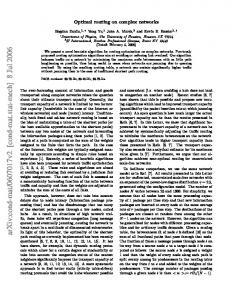
performance is improved because traffic load is fairly distributed over the network and injection is upheld. Several congestion control techniques for InfiniBand networks have been proposed [9],[10],[13]. These techniques make use of message throttling to eliminate congestion. As we mentioned above, reducing injection rate avoids congestion because contention is transferred from network switches to source nodes, but global message latency is dramatically increased. On the other hand the proposed techniques in [15] and [16] , based on IBA congestion notification, allow multipath routing but only support reliable-connection and reliable-datagram communication models [11], whereas the other two InfiniBand models (unreliable-connection, unreliable datagram) are not supported since these techniques do not perform any congestion notification. The congestion control technique presented in this paper is based on DRB routing algorithm [5]. DRB perform a uniform load distribution over alternative paths that exist in the network topology. The algorithm distributes network traffic taking load off the congested area by means of path expansion. Link latency behavior is evaluated in order to detect and avoid congestion. DRB defines how to create alternative paths, and how to use them depending on channel latency. When congestion is detected source nodes are notified in order to configure new possible paths and perform load redistribution according to the communication latency condition. This concept is shown in Fig. 1, where it is observed that latency is monitored in the intermediate nodes and source node is notified about congestion with the recorded channel latency. Notification is performed at destination node by means of an acknowledge message (ACK). When ACKs are received in sources nodes, alternative paths are evaluated and selected based on the value of received latency. It must be noticed that our local distribution mechanism produces a global and collective balancing effect, because path expansion takes place for all sourcedestination channels involved in communications.
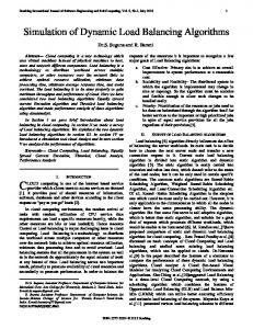
bandwidth, QoS, virtual channels, etc. InfiniBand standard [7] is a powerful architecture designed to deal with I/O devices performance issues and also to conform High Performance Computing clusters due to high bandwidth and low latency that offers. IBA clusters are becoming very popular as discloses top500 supercomputers ranking [14]. In Fig. 2 (a), the utilization for the top 50 is shown. IBA is the most used interconnection standard because of its profitable features. On the other hand, direct topologies like meshes, torus and hypercubes, and also MINs3 like fat-trees [3] have become the most used interconnection topologies for these clusters because they allow several paths between different endnodes. However, even in these topologies congestion may occur. Path configuration between nodes and communication traffic pattern may hassle dynamic network behavior if they are not properly handled. The situation is still worse when static routing, as IBA default routing, is used because static routing does not allow the use of multiple paths to deliver packets. InfiniBand defines arbitrary point to point network architecture (fabric) that provides interconnection for multiples endnodes. Endnodes may be processing nodes hosting one or more CPUs or memory modules, and I/O devices hosting disks. Network interface is accomplished by one or more adapters called Channel Adapters (CAs) that connects endnodes and switches through a link. A network is divided in different subnets. Like endnodes are interconnected by switches, subnets are interconnected by routers.
Fig. 2. Interconnection of top50 supercomputers InfiniBand specifies a protocol stack that divides the architecture in multiple independent layers: physical, link, network, and transport. Link and transport layers are the heart of the IBA architecture because in these layers, packets are created, point to point connections are established, and subnet switching is performed. A virtual channels mechanism (VL) is provided in IBA specs in order to create multiple virtual links over a physical one, improving link throughput. Each IBA network device is represented by a 16 bits local identifier (LID). All packets headers include both source and destination LIDs, and switches make use of them to determine the output port and achieve packet forwarding. IBA Subnets are independently controlled using a well defined Management Model in which several entities or agents communicates themselves to configure network devices and operations. An entity called Subnet Manager (SM) is in the charge of discovering subnet components at network start-up, assigning LIDs and discovering paths between them. These operations are accomplished by management packets (Management Datagram, MADs) that transfer information between the SM and the agents located in each network device, as shown in Fig. 3. SM finds and configures each device with a LID and one path
Fig. 1. Phases of Dynamic Routing Balancing. In DRB path latency is used for monitoring and congestion detection, however IBA standard imposes some restrictions and we have modified our mechanism in order to guaranty full compatibility, as shown in Section 4. The algorithm versatility and good behavior makes possible its implementation over InfiniBand unlike other adaptive congestion control approaches (i.e. Techniques that generates and sends notification packets in the switch2).Next section presents an InfiniBand architecture overview and its facilities to implement our dynamic routing balancing proposal. 3. INFINIBAND OVERVIEW Nowadays, technological advance allows the manufacture of several interconnection networks whose features fulfill HPC systems communication requirements such as point to point connections, low latency, high network 2 IBA switches are not allowed to be source or sink of packets in network normal operation.
3
105
MIN: Multistage Interconnection Networks.
JCS&T Vol. 8 No. 2
July 2008
between endnodes is discovered by default. However, IBA architecture provides multipath support. This is accomplished by a LID masking mechanism that allows assigning multiple names to a single network component. This name multiplicity provides the way to establish multiple paths between the same pair of nodes. Further details about LID masking for multipath implementation are given in the next section. Other important component of management model is the Congestion Control Manager (CCM). This component performs congestion detection and generates notification packets to inform its appearance. IBA CCM specifies a monitoring mechanism in order to measure resources utilization. In case that buffer occupation surpasses a threshold value, congestion control mechanisms are activated. After congestion is detected, switch accomplishes a packet marking using a pair of notification bits in packet header. After marking, packet is forwarded to destination.
4. DYNAMIC ROUTING BALANCING ON IBA Congestion control mechanism proposed in this paper is accomplished within InfiniBand architecture context. IBA standard definitions and operations are not modified so full compatibility is achieved.
Fig. 3. IBA Management model.
Fig. 4. Congestion Notification When destination receives the packet marked with FECN, the congestion control agent sends a Congestion Notification (CN) packet in order to inform source node that congestion was detected in the path that connects both nodes. Notification is carried out in the packet transport header setting the Backward Explicit Congestion Notification bit (BECN). After BECN marking (Fig. 4), the notification message is sent back to source node. Eventually, congestion notifications will be received in the source nodes that have injected packets to the congested area. At this point, the congestion control agent (CCA) configures and evaluates possible alternative paths in order to avoid congestion. Path expansion is performed gradually and it is based on the distribution of received congestion notifications. In other words, ports belonging to congested path are chosen according to the inverse of received congestion notification packets for the following injection. Given a source node with N alternative paths, and let’s be BCi (i: 1...N) the number of congestion notifications received by path Ci, the alternative path Cx will be selected in the following injection according with:
4.1 Model Design IBA switches are provided with a set of monitoring components used to measure buffers occupation in each virtual channel at every switch port. The IBA standard establishes a configurable threshold value relative to buffer size over which congestion is detected. In case that buffer occupation surpasses this threshold, congestion control mechanisms are activated. Threshold is set by CCM and can be configured with several possible values between numbers 0 to 15. Value 0 indicates that no packet is marked at the port and value 15 specifies a very restrictive threshold. When congestion is detected, switches will mark all packets belonging to the virtual-channel buffer that exceeded the threshold value. Marking is accomplished in the packet transport header setting the Forward Explicit Congestion Notification bit (FECN), see Fig. 4. Next packet is forwarded according to the initially specified path.
When a source CA receives information about congestion from the fabric, the congestion control agent reduces the packet injection rate at the port belonging to the congested path. This approach allows congested ports to release the overload of packets contained in buffers and to prevent congestion spreading. Injection reduction will be more restrictive depending on the number of received notification packets. The limit rate is specified by an integer IRD (Injection-Rate Delay) value, which yields a rate limit of B/(1+IRD), where B is the bandwidth of the source CA link. The initial IRD value is determined in path discovery. A Congestion Control Table (CCT) is defined, and each CCT entry contains a different IRD value. As more notifications are received, table entries with higher IRD values are selected. Eventually congestion disappears and the injection rate must be recovered. Congestion control agent performs the injection recovery using a timer. Whenever the timer expires, if no congestion notifications are received injection is gradually recovered (table entries with lower IRD values are selected). As mentioned above, major disadvantage of message throttling mechanism yields in that congestion is eliminated transferring packet contention from switch buffers to the source nodes. Thus congestion is removed, but global latency is increased anyway, and may reach high values in presence of bursty traffic loads. To deal with performance degradation produced by congestion in InfiniBand networks, we propose the application of dynamic routing balancing through the profitable utilization of SM multipath feature, the notification bits in packet transport header, and monitoring mechanisms provided by CCM. DRB technique performs an efficient congestion control because improves link utilization and provides low message latency. This improvement is accomplished by traffic load distribution over multiple paths, unlike message throttling in IBA default mechanism (IBA_CC).
N
ρ (Cx) = 1 / ∑ (BCx / BCi ) i =1
(Eq. 1)
Furthermore, paths are selected according to their length. If path are long in hops, packet transmission time could be high enough and leads to performance degradation, so shortest paths are selected. At network start-up, all information is gathered by SM in order to know the state of switches, links and endnodes. This information is also used in paths construction. IBA specification does not explicitly define an algorithm to accomplish this task. Therefore we have implemented a method to perform a multipath searching. This method is based on the well know Depth-first search (DFS) algorithm [2] with some extra functionality to select disjoint paths only. Alternatives paths are configured and then used for packet delivering when congestion appears.
106
JCS&T Vol. 8 No. 2
July 2008 communication between communicating devices requires transmitting the information through one or more switches.
As mentioned in section 3, SM assigns a local identifier (or LID) to every network port. In order to support multipath feature, a Local Mask Control (LMC) is also specified to mask the LID least significant byte, thus providing up to 2LMC possible LIDs to each port. Destination identifier is located in packet header; when packets are received in the switch the 8 least significant bits (the LMC) are ignored. Hence, it is possible to modify the mask value assigning several LIDs to each CA port. This mask allows the SM to establish several paths between the same pair of nodes. When no more congestion exists, latency value is given mainly by link speed and number of hops between endnodes. Thus, selected path length should be minimal in order to reduce latency value. We use the CCM counter defined in IBA specs to perform path constriction in congestion absence. When counter expires and no more notification packets arrive to source nodes, the connection composed by several disjoints multiple paths is gradually constricted until the original path is retrieved. The used multiple path searching technique and the dynamic routing balancing approach, concerted with CCM congestion detection and monitoring capabilities, provide a congestion control mechanism that improves network performance results in comparison to the original mechanism defined on IBA specification.
(a) Mesh network
(b) Torus network
(c) Fat-Tree network.
Fig. 5. Network Topologies. Direct and Indirect topologies are present in most HPC systems, according with the top500 rank of supercomputers. Features such as: profitable tradeoff between cost and performance, exploiting locality of applications, presence of alternative paths between nodes, multiplexing of flow control information with data packets, higher connectivity, high transmission speed and high bandwidth, are the major reason in the selection of these topologies. 4.2.2 The Switches. The main function of IBA switches is to forward packets towards their destinations. Switches are provided with a set of input channels to accept packets, and a set of output channels to forward packets. An internal crossbar performs the interconnection among input and output channels, and it is managed by the routing and arbitration unit. The functions and capabilities performed in the switch model are shown in Fig. 6. The flow control of packets across the physical channel between neighbor switches is implemented by the Link controller (LC). The LC coordinates the transfer flow control units, and it is provided with buffers to handle with transferred data. An IBA physical channel supports the multiplexing of 16 logical or virtual channels in order to avoid Deadlock. The Virtual channel controller (VC) is responsible for multiplexing the contents of the virtual channels onto the physical channel.
4.2 Models implementation In this sub-section we provide a description about the implementation of the InfiniBand models and topologies used to evaluate the performance of both congestion control mechanisms described above. InfiniBand operations (i.e. path discovery and LID assignment), entities (i.e. SM and CCM) and network components (i.e. switches, links and endnodes) were modeled using the standard simulation and modeling tool OPNET Modeler [8]. The environment provides a Discrete Event Simulator (DES) engine and offers a hierarchical modeling environment with an enhanced C++ language. Network components behavior is defined through a Finite State Machine approach (FSM), which supports detailed specification of protocols, resources, applications, algorithms, and queuing policies. The IBA models are provided with the capabilities specified in the IBA standard architecture [7]: Virtual CutThrough switching, Flow Control mechanisms, Multipath, Virtual Channels, Port Monitoring, Reliable Transport, etc. 4.2.1 The Topologies. We will focus on a classification scheme which categorizes the known interconnection networks into three major classes based on the network topology: • Shared-Medium Networks (i.e. Ethernet, Token Bus, and Token Ring). • Direct Networks (2D and 3D bidirectional Torus and Meshes, Rings, and Hypercubes). • Indirect Networks (Multistage Interconnection Networks, InfiniBand, Myrinet, ServerNet). This classification scheme is focused on networks that have been implemented, and it is not complete because other new and innovative interconnections, such as mobile and optical communications are no present. However, for the HPC systems under evaluation in this paper, it is a suitable classification scheme. In shared-medium networks, the transmission medium is shared by all communicating nodes. By contrast, direct networks (as shown in Fig.5 (a) and (b)) provide point-topoint links to directly communicate processor nodes in the network. Instead of directly connecting the communicating nodes, indirect networks (Fig. 5 (c)) connect processors by means of one or more switches. If several switches exist, they are interconnected using point to point links. In this case, any
Fig. 6. Switch Organization. The Crossbar unit was designed to provide a full connectivity between switch input buffers and switch output buffers. Buffers are provided in order to store messages in transit, which are waiting for an output port to be released. These buffers are managed with the First InFirst Out approach (FIFO). Depending on the used switching technique [3] the buffer size will be an integer number of the flow control unit size (for wormhole
107
JCS&T Vol. 8 No. 2
July 2008
switching) or integral number of the packet size (for Virtual Cut-Through or Store and Forward switching). The routing function is responsible for providing an output port to the incoming packets in the switch, and it is implemented in the Routing and port arbitration unit. IBA specifies a Forwarding Tables mechanism in order to route packets in the network. Crossbar requests belonging to different ports must be fairly serviced in order to avoid starvation and concurrent requests for the same output must be arbitrated. Thus a round robin arbitration policy has been implemented to provide fair crossing priority for packets through the switch. The IBA Management Model is endowed with the necessary entities mentioned above. The Subnet Manager configures the network parameters, and discovers devices in order to assign LIDs proving multipath support. Finally the Congestion Control Manager performs congestion monitoring detection and notification.
control policy through several experiments. evaluation is presented in the following section.
This
5. PERFORMANCE EVALUATION In this section, we present the results of simulating the proposed Dynamic Routing Balancing (DRB) mechanism and InfiniBand standard congestion control technique (IBA_CC) on several topologies under different traffic workloads. In order to evaluate global interconnection network performance, throughput and latency metrics have been selected. Latency metric represents time spent in message delivery from its generation, and is measured in milliseconds. Throughput metric represents traffic received load vs. traffic offered load, and is measured in bits/µs. Both metrics give a global and average network performance description. Evaluation methodology is divided in two major parts. First, we evaluate the proposed technique on torus and mesh topologies under the “Perfect Shuffle” workload [3], a well known synthetic communication pattern taken from a numerical application. This workload can be defined as follows: For a network source node, represented in the binary format as: bn−1, bn−2. . . b1, b0.Under Perfect shuffle traffic pattern, source node communicates with the node named: bn−2, bn−3. . .b0, bn−1 (1 bit left rotation). Configuration parameters were selected as follows: Switch threshold is set at 80% of port buffer size and timer expiration is set at 100 µs, for both congestion control approaches. Injection Rate Delay (used in IBA_CC) is incremented in 5 µs, each time that 10 congestion notifications are received. Finally, a maximum of four alternative disjoint paths is used in DRB approach; and one new path is opened each time that 10 notifications are received. The second part of the evaluation is designed to perform a network response analysis under Hot-spot traffic pattern in order to evaluate DRB dynamic behavior and traffic load distribution over the network links.
4.2.3 The Endnodes. The Endnode includes a processor node that executes the application generating and consuming packets, and also a network interface to connect processor nodes with network switches. The functions and capabilities performed in the endnode model are shown in Fig. 7. The processor node in the Endnode generates link layer data messages according to a specific traffic pattern of the application. The network interface includes a single port. As in the case of switch ports, it supports virtual channels using a Virtual channel controller, and flow control is addressed by means of the Link controller that connects the network interface to the physical link. The sender takes the message generated by the processor node and splits it in several packets according with the MTU of the network interface. Packets are numbered to measure the level of out of order delivery, which may be caused by some adaptive routing algorithms. Finally a virtual channel is selected by the sender in order to forward packets. Similarly, the receiver is responsible for gather the packets on the virtual channels, analyze the packet order, merge the packets onto the message and finally deliver the message to the processor node. The Management model is also implemented at Endnode level in order to: perform FECN bit analysis, conform a Congestion Notification packet, configure and evaluate possible alternative paths, and perform path constriction in absence of congestion.
5.1 Performance in torus topology. Fig. 8 shows the performance of a 64 nodes InfiniBand network connected in two-dimensional torus topology. DRB offers better results than IBA congestion control technique. Difference between shapes is much increased for higher traffic loads. When low offered load is injected into network (a bandwidth smaller than 400 bits/µs, Fig. 8 (a)), both congestion control techniques perform a similar behavior and Latency remains bounded between 10…100μs (see flat part of Fig. 8 (b)). This similarity implies that DRB does not change the network performance without congestion. Therefore, overhead is not introduced in network normal operation for low traffic loads. When the communication load is increased between 400 and 800 bits/µs, message latency achieved by our method is lower (80μs to 100μs) in comparison to the obtained with InfiniBand technique (80μs to 100ms) because source nodes begin to send packets to destination through alternative paths in DRB approach, while with IBA_CC packets keep waiting in source node to be injected. For high traffic load injection (over 800 bits/µs), DRB uses the maximum number of available paths to deliver messages. We configured a maximum expansion of four alternatives path in this experimentation and results show that proposed approach perform a remarkably inferior latency (100μs to 50ms) that InfiniBand congestion control mechanism (more than 200ms). As message latency is reduced, also network throughput is significantly increased. This throughput increment improves resources utilization and traffic distribution over the networks links. Fig. 8 (a) shows received traffic load as a function of the offered traffic load. DRB achieves a higher received load, and network saturation is reached before with IBA_CC. Performance improvement accomplished for the proposed mechanism is near 35%.
Fig. 7. Endnode Architecture. The development of mentioned IBA models allows performing the evaluation of the proposed congestion
108
JCS&T Vol. 8 No. 2
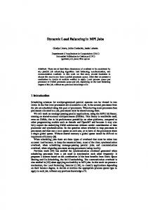
July 2008 Before Hot-spot, network utilization is bounded to 30% (750 Mbps)4. At 42.5 sec approx. Hot-spot is produced in links 1,2,3,4 and 5 incrementing the communication load in 230% for this network area. Fig.10 (a) show that network using the IBA_CC approach needs more than 1750 Mbps to handle the Hot-spot, while in DRB case, network needs 1000 Mbps approx. to satisfy the load demand (Fig. 10(b)). Efficient communication load distribution provided by DRB mechanism, allows better utilization of network components.
(a)
(a)
(b)
Fig. 8. 64 nodes IBA network performance. Throughput and latency for a torus topology. 5.2 Performance in mesh topology. Performance of a 32 nodes InfiniBand network connected in mesh topology is shown in Fig. 9. Due to physical features, mesh topologies offer less possible alternative paths than torus. Therefore, produced throughput is slightly worse in this case (Fig. 9 (a)). As like in the torus network, DRB behavior is quite similar to IBA_CC mechanism at low communication load. However, latency is remarkably improved for network working at maximum traffic load, in which better performance is achieved (Fig. 9 (b)). As a consequence dynamic routing balancing technique is able to handle greater communication loads, and it offers superior performance than IBA_CC method due to load distribution over several paths. This improvement can be seen in both studied topologies where a reduction of 66% and 42% in latency is accomplished. Moreover, flat area of latency curve is upheld for higher values of traffic load, increasing the network usability. It must be noticed that reduction is due to the fact that DRB takes advantage of the network path multiplicity in order to send packets to destination. This is not the case for IBA_CC technique where packets must wait certain amount of time before being injected.
(b) Fig. 9. 32 nodes IBA network performance.
Throughput and latency for a mesh topology. Results show that dynamic routing balancing improves network performance approximately in a 43% compared with IBA_CC. Communication load peaks are efficiently eliminated by DRB due to traffic distribution. Therefore, packets contention is avoided in network buffers and latency remains bounded. As a consequence of peaks reduction, network load may be increased and a better performance can be achieved with the same amount of resources. The proposed mechanism offers better results under “Hot-spot” traffic patterns that present an important local load-concentration. Communication load is efficiently balanced and distributed over several paths increasing the interconnection network performance. 6. CONCLUSION In this paper we propose a congestion preventing scheme for InfiniBand networks. This technique is based on the Dynamic Routing Balancing mechanism. DRB eliminates performance degradation produced by packet contention in network resources. Congestion elimination is accomplished distributing the communication load over several alternative paths. Unlike message throttling techniques, like proposed in IBA specs, DRB allows sources nodes to preserve the injection rate. Hence, message latency is reduced and network performance is
5.3 Dynamic behavior In order to evaluate DRB and IBA_CC dynamic responses, we have analyzed the network behavior under “Hot-spot” traffic pattern. When Hot-spot occurs, several packets compete for resources in a focused network area. We have analyzed and compared both techniques under a very adverse communication load, as shown in Fig.10. Point to point throughput (in bit/μs) versus execution time (in seconds) is plotted in order to evaluate the load distribution over all network links when a Hot-spot appears.
4
109
Maximum achievable BW for a single IBA link is 2,5Gbps
JCS&T Vol. 8 No. 2
July 2008 Furthermore, IBA specs switches are not allowed to be source or sink of packets in network normal operation. However, this restriction may be changed in the near future providing some intelligence to switches in order to solve packets congestion locally, and also to inform sources nodes improving the response time to congestion problems.
improved. Experimentation results show that throughput is increased in 35% and latency is reduced in 42% - 66% compared with IBA message throttling technique. Network dynamic behavior was also evaluated and traffic load peaks are efficiently reduced (43%) by communication-load balancing approach.
7. REFERENCES [1] E. Baydal, “A Family of Mechanisms for Congestion Control in Wormhole Networks”, IEEE Trans. Parallel Distrib. Syst. vol 16 , pp.772-784, sept. 2005. [2] T. Cormen, C. Leiserson., R. Rivest, C. Stein. “Introduction to Algorithms”, second edition, MIT Press and McGraw-Hill, 2001. [3] W. Dally, B. Towles. “Principles and practices of interconnection networks”, Morgan Kaufmann publishers, 2004. [4] J. Duato, I. Johnson, J. Flich, F. Naven, P. Garcia, T. Nachiondo, “A new scalable and cost-effective congestion management strategy for lossless multistage interconnection networks,” in 11th International Symposium on HPCA-11, 2005, pp. 108-119. [5] D. Franco, I.Garcés, and E. Luque, 1999. "A new method to make communication latency uniform". Procc. of ACM International Conference on Supercomputing (lCS99), 210- 219. [6] P.J. Garcia, F.J. Quiles, J. Flich, J. Duato, I. Johnson, F. Naven, "RECN-DD: A Memory-Efficient Congestion Management Technique for Advanced Switching," in ICPP, 2006, pp. 23-32. [7] InfiniBand Trade Association, “InfiniBand Architecture Specification vers.1.2,” June 2008, http://www.InfiniBandta.com/ [8] OPNET Technologies, “Opnet Modeler Accelerating Network R&D,” June 2008, http://opnet.com. 2008. [9] G. Pfister ”Solving Hot Spot Contention Using InfiniBand Architecture Congestion Control,” in Ion High Performance Interconnects for Distributed Computing, 2005. [10] J.R Santos, Y. Turner, G. Janakiraman, “End-to-end congestion control for InfiniBand,” in TwentySecond Annual Joint Conference of the IEEE Computer and Communications Societies, INFOCOM 2003, vol.2, 2003, pp. 1123-1133. [11] T. Shanley, “InfiniBand Network Architecture”, Addison Wesley, 1999. [12] A. Singh, W. Dally, B. Towles, AK. Gupta “Globally Adaptive Load-Balanced Routing on Tori”, IEEE Computer Architecture Letters, vol. 3, no. 1, pp. 6–9, jan 2004. [13] Y. Shihang, G. Min, I. Awan, "An Enhanced Congestion Control Mechanism in InfiniBand Networks for High Performance Computing Systems," in Proceedings of the 20th International Conference on Advanced Information Networking and Applications, AINA 2006, IEEE Computer Society, vol 1, april 2006, pp. 845-850, [14] Top500 Supercomputers Site, “Interconnect Family share for 06/2008,” June 2008, http://www.top500.org. [15] A. Vishnu, M. Koop, A. Moody, A. Mamidala, S. Narravula, D. Panda, "Hot-Spot Avoidance With Multi-Pathing Over InfiniBand: An MPI Perspective," In Proceedings of the Seventh IEEE international Symposium on Cluster Computing and the Grid, CCGRID, IEEE Computer Society, 2007, pp. 479-486. [16] L. Xuan-Yi, C. Yeh-Ching, H. Tai-Yi, “A multiple LID routing scheme for fat-tree-based InfiniBand networks,” in Proceedings of the 18th Parallel and Distributed Processing Symposium, 2004, pp. 26-30.
(a)
(b) Fig. 10. Dynamic response. Hot-spot avoidance. Our mechanism was adapted in order to work with two independent entities defined in IBA management. The subnet manager (SM) is configured to discover network topology, assigning local identifiers (LIDs) and local mask control (LMC) to each device port. Thus, alternatives paths between same source-destination pair are achieved (multipath feature). The congestion detection and notification capabilities, provided by congestion control manager (CCM) are used to perform network monitoring. However, message throttling is deactivated. Therefore, when notification messages are received, the proposed congestion control technique performs a load balancing over the network links using alternatives paths. As both management entities are defined in InfiniBand specs, our method does not require any modification in the standard and fully IBA compatibility is provided. The proposal described in this paper open several research alternatives in the interconnection network design. First of all, the hardware implementation of DRB in the IBA components will allow studying the behavior of the proposed method for several applications and more complex topologies, in order to quantify the notification messages overhead in a real environment. Also, this exhaustive evaluation is intended to enhance DRB features, improving the packet marking method and the alternative path selection mechanism.
110