Int. J. on Recent Trends in Engineering and Technology, Vol. 10, No. 2, Jan 2014
Dynamic Simulation of Induction Motor Drive using Neuro Controller P. M. Menghal1, A. Jaya Laxmi 2, N.Mukhesh3 1
Faculty of Degree Engineering, Military College of Electronics and Mechanical Engineering, Secunderabad & Research Scholar, EEE Dept., Jawaharlal Nehru Technological University, Anantapur-515002, Andhra Pradesh, India Email:
[email protected] 2 Dept. of EEE, Jawaharlal Nehru Technological University, College of Engineering, Kukatpally, Hyderabad-500085, Andhra Pradesh, India Email:
[email protected] 3 Research Scholar, Dept. of E &C, Jawaharlal Nehru Technological University, College of Engineering, Kukatpally, Hyderabad-500085, Andhra Pradesh, India
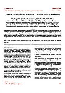
[email protected] Abstract— Induction Motors are widely used in Industries, because of the low maintenance and robustness. Speed Control of Induction motor can be obtained by maximum torque and efficiency. Apart from other techniques Artificial Intelligence (AI) techniques, particularly the neural networks, improves the performance & operation of induction motor drives. This paper presents dynamic simulation of induction motor drive using neuro controller. The integrated environment allows users to compare simulation results between conventional, Fuzzy and Neural Network controller (NNW).The performance of fuzzy logic and artificial neural network based controller's are compared with that of the conventional proportional integral controller. The dynamic Modeling and Simulation of Induction motor is done using MATLAB/SIMULINK and the dynamic performance of induction motor drive has been analyzed for artificial intelligent controller. Index Terms— Neuro Network(NNW), PI Controller, Fuzzy Logic Controller(FLC), Sugeno Fuzzy Controller
I. INTRODUCTION Three phase Induction Motor have wide applications in electrical machines. About half of the electrical energy generated in a developed country is ultimately consumed by electric motors, of which over 90 % are induction motors. For a relatively long period, induction motors have mainly been deployed in constantspeed motor drives for general purpose applications. The rapid development of power electronic devices and converter technologies in the past few decades, however, has made possible efficient speed control by varying the supply frequency, giving rise to various forms of adjustable-speed induction motor drives. In about the same period, there were also advances in control methods and Artificial Intelligence (AI) techniques. Artificial Intelligent techniques mean use of expert system, fuzzy logic, neural networks and genetic algorithm. Researchers soon realized that the performance of induction motor drives can be enhanced by adopting artificial-intelligence-based methods. The Artificial Intelligence (AI) techniques, such as Expert System (ES), Fuzzy Logic (FL), Artificial Neural Network (ANN or NNW), and Genetic Algorithm (GA) have recently been applied widely in control of induction motor drives. Among all the branches of AI, DOI: 01.IJRTET.10.2.15 © Association of Computer Electronics and Electrical Engineers, 2014
the NNW seems to have greater impact on power electronics & motor drives area that is evident by the publications in the literature. Since the 1990s, AI-based induction motor drives have received greater attention. Apart from the control techniques that exist, intelligent control methods, such as fuzzy logic control, neural network control, genetic algorithm, and expert system, proved to be superior. Artificial Intelligent Controller (AIC) could be the best controller for Induction Motor control [1-6]. Since the unknown and unavoidable parameter variations, due to disturbances, saturation and change in temperature exists; it is often difficult to develop an accurate system mathematical model. High accuracy is not usually of high importance for most of the induction motor drive. Controllers with fixed parameters cannot provide these requirements unless unrealistically high gains are used. Therefore, control strategy must be robust and adaptive. As a result, several control strategies have been developed for induction motor drives within last two decades. Much research work is in progress in the design of hybrid control schemes. Fuzzy controller conventionally is totally dependent to memberships and rules, which are based broadly on the intuition of the designer. This paper tends to show Neuro controller has edge over fuzzy controller. Sugeno fuzzy controller is used to train the fuzzy system with two inputs and one output [10-12].The performance of fuzzy logic and artificial neural network based controllers is compared with that of the conventional proportional integral controller. II. DYNAMIC MODELING & SIMULATION OF INDUCTION M OTOR DRIVE The induction motors dynamic behavior can be expressed by voltage and torque which are time varying. The differential equations that belong to dynamic analysis of induction motor are so sophisticated. Then with the change of variables the complexity of these equations decrease through movement from poly phase winding to two phase winding (q-d). In other words, the stator and rotor variables like voltage, current and flux linkages of an induction machine are transferred to another reference model which remains stationary[1-6].
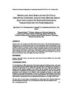
Figure. 1 d q Model of Induction Motor
In Fig.1 stator inductance is the sum of the stator leakage inductance and magnetizing inductance (Lls = Ls + Lm), and the rotor inductance is the sum of the rotor leakage inductance and magnetizing inductance (Llr = Lr + Lm). From the equivalent circuit of the induction motor in d-q frame, the model equations are derived. The flux linkages can be achieved as: 1 = (1) 1
= =
(2) (
)
(3)
45
1
=
+
(
)
(4)
By substituting the values of flux linkages in the above equations, the following current equations are obtained as: =
(5) (
=
)
(6)
=
(7)
= Where follows:
mq
md
(
)
(8)
are the flux linkages over Lm in the q and d axes. The flux equations are written as =
+
=
=
(9)
(10)
+
1
I as:
+
r
=
1 1
+
(11)
1
is related to the torque by the following mechanical dynamic equation +
+
2
(12)
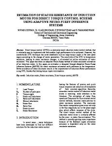
then r is achievable from above equation, where: p: number of poles. J: moment of inertia (kg/m2). In the previous section, dynamic model of an induction motor is expressed. The model constructed according to the equations has been simulated by using MATLAB/SIMULINK as shown in Fig.2 in conventional mode of operation of induction motor. A 3 phase source is applied to conventional model of an induction motor and the equations are given by: = = =
(
2
)
2 2
(13) 2 3
sin
t+
2 3
(14) (15)
By using Parks Transformation, voltages are transformed to two phase in the d-q axes, and are applied to induction motor. In order to obtain the stator and rotor currents of induction motor in two phase, Inverse park transformation is applied in the last stage [6]. III. F UZYY LOGIC CONTROLLER The speed of induction motor is adjusted by the fuzzy controller. The following equation is used to represent the fuzzy triangular membership functions:
46
Figure. 2. Simulated Induction Motor Model in Conventional Mode
0