Email: {wuebben,rinas,boehnke,kuehn,kammeyer}@ant.uni-bremen.de. Abstractâ Layered ... This new algorithm is compared to V-BLAST by simulation results ...
4TH INTERNATIONAL ITG CONFERENCE ON SOURCE AND CHANNEL CODING, BERLIN, JANUARY 2002
1
Efficient Algorithm for Detecting Layered Space-Time Codes D. W¨ ubben, J. Rinas, R. B¨ohnke, V. K¨ uhn and K.D. Kammeyer Department of Communications Engineering University of Bremen, Germany Email: {wuebben,rinas,boehnke,kuehn,kammeyer}@ant.uni-bremen.de
Abstract— Layered space-time codes have been designed to exploit the capacity advantage of multiple antenna systems in Rayleigh fading environments. In this paper, we present a new efficient detection algorithm based on a sorted QR decomposition. It only needs a fraction of computational effort compared to the standard detection algorithm requiring multiple calculations of the pseudo inverse of the channel matrix. The derived algorithm is not restricted to layered space-time architectures, but can generally be used for detection in vector channel systems. Keywords— Layered space-time codes, diversity, MIMO system, wireless communication.
I. Introduction In a Rayleigh fading environment, multiple antenna systems provide an enormous increase in capacity compared to single antenna systems [1]. Consequently, multiple-input multiple-output (MIMO) systems are predestined for high data rate wireless communications. Space-Time codes are designed to exploit this high capacity by using space as a second dimension of coding [2, 3]. Layered space-time (LST) codes are a special kind of space-time codes with the advantage of a feasible decoding complexity. The original D-BLAST (Diagonal Bell Labs Layered Space Time) architecture proposed by Foschini [4] uses a diagonally layered coding structure in which code blocks are dispersed across diagonals in space-time. Thereby, an “averaged” channel which is the same for all layers is achieved and the probability of deep fades is reduced. Due to the diagonal arrangement of the code blocks, D-BLAST is not feasible for real time implementations. A simplified version was proposed in [5] and is known as V-BLAST (Vertical BLAST). It associates each layer with a specific transmit antenna wich leads to an easier detection and decoding process. For detecting the layers, the multiple calculation of the pseudo inverse of the channel matrix is necessary. In order to significantly reduce the computational effort of detection, we introduce a new and very efficient way of detecting layered space-time codes. This work was supported in part by the German ministry of education and research (BMBF) within the project HyEff (project no. 01 BU 153) and the German national science foundation (DFG) within the project AKOM (project #Ka 841/9-1)
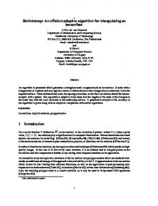
This approach utilizes an adjusted QR decomposition (QRD) by sorting the detection sequence due to exchanging the columns of the channel matrix. This new algorithm is compared to V-BLAST by simulation results and by an estimation of the computational effort. The remainder of this paper is organized as follows. In section II, the MIMO system and the LST architecture are described. In section III, V-BLAST and a QRD based algorithm for detecting LST architectures are reviewed. The new approach is introduced in section IV and the performance of both detection algorithms are compared in section V. In section VI forward correction coding is added in each layer and the computational effort of both detecting algorithms is compared in section VII. A summary and concluding remarks can be found in section VIII. II. System description We consider the multi antenna system with nT transmit and nR ≥ nT receive antennas shown in Fig. 1. The data is demultiplexed in nT data substreams of equal length (called layers). These substreams are mapped into M -PSK or M -QAM symbols c1 , . . . , cnT . Alternatively, a forward error correction (FEC) code can be used to encode the data substreams before mapping. We will investigate the application of FEC code in section VI and assume uncoded symbols until then. The substreams are organized in frames of length L and are transmitted over the nT antennas at the same time. The system is equal to V-BLAST proposed in [4] and denoted as Layered Space-Time (LST) architecture in [6]. Transmitter Data
Receiver
Layer 1
c1
Layer 2
c2
Layer nT
cnT
x1
H
x2
Detector
rec. Data
xnR
Fig. 1. Model of a MIMO system with nT transmit and nR receive antennas
In order to describe the MIMO system, one time slot of the time-discrete baseband model of the
4TH INTERNATIONAL ITG CONFERENCE ON SOURCE AND CHANNEL CODING, BERLIN, JANUARY 2002
MIMO system is investigated. Let c = (c1 c2 . . . cnT )T denote the vector of transmitted symbols, then the corresponding received signal vector x = (x1 x2 . . . xnR )T is calculated by x=H·c+ν .
(1)
In equation (1), ν = (ν1 ν2 . . . νnR )T depicts the vector of noise terms at the nR receiving antennas, assuming uncorrelated white gaussian noise of variance N0 /2 per dimension for all antennas. The transmitted symbols are normalized so that the average received energy per bit is one. The nR × nT channel matrix h1,1 . . . h1,nT .. .. .. (2) H= . . . hnR ,1
...
hnR ,nT
contains i.i.d. complex fading gains hj,i describing the tap gains between transmit antenna i and receive antenna j. Column i of H is denoted by hi and represents the single-input multiple-output (SIMO) channel between transmit antenna i and the nR receive antennas. We assume a static flat-fading environment, i.e. the channel matrix H is constant over a frame and changes independently from frame to frame. The distinct fading gains are assumed to be uncorrelated and are perfectly known by the receiver. III. Detecting Layered Space-Time Codes In this paragraph, two different detection algorithms for the LST architecture are described. First, the standard detection algorithm proposed by BellLabs [5] and known as V-BLAST is depicted. Shiu and Kahn utilized the QR decomposition of the channel matrix for the detection of the layers to derive error bounds for V-BLAST and D-BLAST in [6]. They presumed the knowledge of the best detection sequence, but did not discuss the problem of an efficient assorting algorithm, which is done in section IV of this paper. A. BLAST-Algorithm It is obvious from equation (1) that the received signals are a linear combination of the nT transmitted signals. The optimum way of recovering the nT signals at the receiver would be maximum-likelihood detection, which is not feasible due to the enormous complexity. In [4] and [5], Foschini et al. proposed a successive interference cancellation technique which nulls the interferer by linearly weighting the received signal vector with a zero-forcing (ZF) nulling vector. In every detection step, all signals but one are regarded as interferer. By applying the nulling vector to interference cancellation, the influence of these signals is nulled out, the target signal is detected
2
and subsequently subtracted from the received signal vector (Interference Cancellation). For detecting signal i, the nulling vector wi has to be orthogonal to columns hl , l 6= i of the channel matrix. The condition1 � 1 l=i T (3) wi · h l = 0 l 6= i is fulfilled by the i-th row of the Moore-Penrose pseudo-inverse �−1 H G := H+ := HH H H , (4)
of the channel matrix H. With g(i) denoting row i of G, the received signal vector x is linearly weighted with the nulling vector wiT = g(i) and the result yi
= wiT · x = g(i) · (H · c + ν) = ci + ν˜i .
(5)
is used as a decision statistic for the i-th substream where ν˜i = g(i) · ν denotes the actual noise. By applying the quantization operation Q[·] appropriate to the signal constellation, signal i can be estimated: cˆi = Q[yi ] .
(6)
The interference caused by the detected signal cˆi is now subtracted from the received signal vector xi xi+1 = xi − hi · cˆi
(7)
and the corresponding column in the channel matrix is set to zero. The indexed variables (Hi ,Gi ,xi ) denote from now on the specific variables in detection step i, beginning with the assignment (H1 = H, G1 = G, x1 = x) in the first step. Using the nomenclature introduced in [5], Hi+1 := Hii describes the nulling of column i of the channel matrix Hi and corresponds to an equivalent system with nT − i transmit and nR receive antennas. Thus, the pseudo inverse of this reduced channel matrix Hi+1 is used to calculate the nulling vector for detecting layer i + 1. The order of detecting affects the error probability of the algorithm [5]. The sequence S = {k1 , k2 , . . . , knT } is defined as a permutation of the numbers 1, 2, . . . , nT to depict a specific detection sequel. Thus the values yk1 , yk2 , . . . , yknT are filtered one by one, the transmitted signals cˆk1 , cˆk2 , . . . , cˆknT are estimated and the interference is cancelled step by step according to equations (5) to (7). In order to derive the minimum total error probability, it is optimal always to choose and detect the layer with the largest post detection signalto-noise ratio [5]: � E |cki |2 1 ∼ (8) SN Rki =
. E {|nki |2 } kwki k2
g(ki ) 2 1 The transpose and conjugate transpose (Hermitian) of x are denoted by xT and xH , respectively.
4TH INTERNATIONAL ITG CONFERENCE ON SOURCE AND CHANNEL CODING, BERLIN, JANUARY 2002 (k )
Consequently, it is optimal to choose the row gi i of Gi with minimal norm and thus detect the associated signal cki in detection step i. The whole detection algorithm is shown in Fig. 2. (1) (2) (3) (4) (5) (6) (7) (8) (9)
3
the upper layer signals c1 , . . . , ck−1 and hence the lowest layer (transmit signal cnT ) is described by ynT = rnT ,nT · cnT + ηnT .
(14)
Then, the decision statistic ynT is independent of the remaining transmit signals and can be used to estimate cˆnT � � ynT cˆnT = Q (15) rnT ,nT
for i = 1, . . . , nT G i = H+ i
(j) 2 ki = arg min gi j (k )
wkTi = gi i yki = wkTi · xi cˆki = Q[yki ] xi+1 = xi − hki · cˆki Hi+1 = Hki i end
by applying the quantization operation Q[·]. For detecting layer nT − 1, the interference term rnT −1,nT · cˆnT is eliminated in the modified received signal
Fig. 2. V-BLAST algorithm for detecting layered space-time signals
B. QR decomposition of the channel matrix In [6], Shiu and Kahn used the QR decomposition of the channel matrix H to derive bounds for the error probability of LST codes. Therefore, the nR × nT channel matrix H H = Q · R,
(9)
ynT −1 = rnT −1,nT −1 ·cnT −1 +rnT −1,nT ·cnT +ηnT −1 . (16) Consequently, an interference free decision statistic to estimate cnT −1 is obtained under the assumption cˆnT = cnT . Detecting layer k = nT − 1, . . . , 1 takes place in an equivalent way. With previous decisions cˆk+1 , . . . , cˆnT , the interference term dˆk is calculated and cancelled out in the modified received signal yk . Assuming that all previous decisions are correct (dˆk = dk ), the value zk = yk − dˆk = rk,k · ck + ηk
(17)
is factorized into the unitary nR × nT matrix Q and the upper triangular nT × nT matrix R. By denoting the column i of H by hi and column i of Q by qi , the decomposition in equation (9) is described columnwise by r1,1 . . . r1,nT .. .. (h1 . . . hnT ) = (q1 . . . qnT )· . . .
is free of interference and thus it can be used to detect ck with cˆk = Q[zk /rk,k ]. As already stated, the order of detection is crucial for the error probability of the LST system due to the risk of error propagation [5]. When using the QR decomposition for detection, the sequence of detection is achieved by permutating the elements of c and the corresponding columns of H and thereby results in different matrices Q and R. The optimum R maximizes � E |ck |2 |rk,k |2 SN Rk = ∼ |rk,k |2 (18) E {|nki |2 }
y = QH · x = R · c + η .
in each step of the detection process (corresponds to the maximization of |rk,k | for k = nT , . . . , 1) and can be found by performing O(n2T /2) QR decompositions of permutations of H [7]. In order to reduce the computational effort of finding a detection sequence, we derive a suboptimal but less complex algorithm for sorting in the next section.
0
rnT ,nT
(10) By multiplying equation (1) from the left with the Hermitian matrix of Q, a nT × 1 modified received signal vector (11)
is created from the nR × 1 received signal vector x. Since Q is unitary, the statistical properties of the noise term η = QH · ν remain unchanged. Element k of vector y becomes yk = rk,k · ck + ηk + dk
(12)
with the interference term dk =
nT X
rk,i · ci .
(13)
i=k+1
Thus, yk depends on the weighted transmit signal rk,k · ck , the noise ηk and the interference term dk . Since R is upper triangular, dk is independent of
IV. Sorted QR decomposition In this section, a new and very efficient approach that comes close to the error performance of VBLAST is introduced. It is basically an extension of the modified Gram-Schmidt algorithm [8] by ordering the columns of H in each orthogonalization step. In order to describe this new algorithm, we first review the modified Gram-Schmidt algorithm without sorting. In the subsequent the motivation for the sorted approach and the description of the sorted QR decomposition are presented.
4TH INTERNATIONAL ITG CONFERENCE ON SOURCE AND CHANNEL CODING, BERLIN, JANUARY 2002
A. Modified Gram-Schmidt The Gram-Schmidt algorithm computes matrix R of the QR decomposition line by line from top to bottom and matrix Q columnwise from left to right [8]. Starting with the assignment Q := H = (h1 , . . . , hnT ), the following operations are executed in every step i = 1, . . . , nT : Assign norm of column vector qi to the diagonal element ri,i of the upper triangular matrix R (ri,i = kqi k) and subsequently scale qi to length one (qi = qi /ri,i ). • Orthogonalize columns ql , i < l ≤ nT , with regard to qi , i.e. subtract the component parallel to qi . The component in the direction of qi is equal to the projection ri,l = qH i · ql and the orthogonal part is calculated by ql = ql − ri,l · qi .
•
In every step i the vectors q1 , . . . , qi form an orthonormal basis of the vector space spanned by h1 , . . . , hi and the vectors ql , i < l ≤ nT , contain the components of the corresponding hl orthogonal to this vector space. The diagonal element ri,i denotes the length of hi orthogonal to q1 , . . . , qi−1 or h1 , . . . , hi−1 , respectively. Furthermore, the coefficients ri,l specify the component of hl , i < l ≤ nT , in the direction of qi . B. Sorted Gram-Schmidt From the explanation in section IV-A it is obvious that the modified Gram-Schmidt process calculates the diagonal elements from r1,1 to rnT ,nT . As already stated, it would be optimal to maximize |rk,k | by permutating the rows of Q in every detection step, i.e from rnT ,nT to r1,1 . Thus, the optimal detection sequence SOPT maximizes SN Rk in every detecting step k, k = nT , . . . , 1. Unfortunately, the search for SOPT is very costly, because it requires O(n2T /2) QR decompositions. The sorted Gram-Schmidt process (Sorted QR Decomposition, SQRD) proposed here searches for the detection sequence S that achieves small SN Rk in the upper layers. Consequently, the absolut values of the diagonal elements rk,k in the upper left area of the triangular matrix R are small. Thus, a detection fault caused by the little signal-to-noise ratio SN Rk influences only few layers 1, . . . , k − 1 through error propagation. In order to illustrate the functionality, one orthogonalization step i of the SQRD algorithm is explained in detail. The first i − 1 elements of the sequence S are already calculated and therefore the vectors q1 , . . . , qi−1 are fixed. The ordering of the remaining columns is variable and is determined by the ordering rule in order to force small signal-tonoise ratios for the upper layers. Therefore, the column with minimal norm is chosen from the vectors qi , . . . , qnT and denoted with qki . The corresponding hki has the smallest component orthogonal to
4
the space spanned by q1 , . . . , qi−1 , wich leads to the smallest ri,i of the possible permutations in step i and thereby the smallest SN Ri . The only change to the modified Gram-Schmidt algorithm is the reordering of the columns of Q. In every decomposition step i the column qi , . . . , qnT with the minimal length orthogonal to the already spanned vector space q1 , . . . , qi−1 is chosen. The whole algorithm for the signal detection is shown in Fig. 3. It consists of a decomposition part (line (1) to (11)) and a detection part (line (12) to (17)). In the decomposition part, the ordering is done in line (3) and (4) and provides the permutation vector S, the orthogonal matrix Q and the upper triangular matrix R. In the detection part, the received signal vector is sorted according to the permutation S, and the modified received signal vector y is calculated (line (12)). The following lines (13) to (17) represent the iterative detection process described in section III-B. SQRD Algorithm (1) R = 0, Q = H, S = (1, . . . , nT ) (2) for i = 1, . . . , nT (3) ki = arg min kql k2 l=i,...,nT
(4) exchange col. i and ki in Q, R, S (5) ri,i = kqi k (6) qi = qi /ri,i (7) for l = i + 1, . . . , nT (8) ri,l = qH i · ql (9) ql = ql − ri,l · qi (10) end (11) end Signal Detection (12) y = QH · x (13) for k = nT , . . . , 1 Pn T (14) dˆk = i=k+1 rk,i · cˆi (15) zk = yk − dˆk (16) cˆk = Q[zk /rk,k ] (17) end (18) Permutate cˆ according to S Fig. 3. SQRD algorithm and signal detection of layered space-time codes
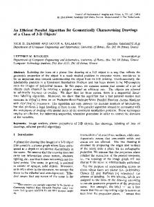
V. Performance Analysis The performance of the proposed SQRD detection algorithm and the standard LST detection algorithm (V-BLAST, [5]) was compared by means of Monte Carlo simulations for several scenarios. Fig. 4 shows the bit error rates (BER) for an uncoded transmission of QPSK symbols in a system with nT = 8 and nR = 12 antennas. The iterative methods unsorted QR decomposition, SQRD and V-BLAST achieves a performance enhancement in comparison to the simple multiplication with the
4TH INTERNATIONAL ITG CONFERENCE ON SOURCE AND CHANNEL CODING, BERLIN, JANUARY 2002
10
−1
−1
E
0
BER
−2
BER
10
E
−3
∼ ( Nb )−2
10
0
−4
−2
10
−3
10
10
E
−5
0
0
0
5
10
15
Eb N0
20
in dB
2
4
6
8
10
Eb N0
12
in dB
14
16
18
20
Fig. 4. Simulation with nT = 8 and nR = 12 antennas, uncoded QPSK symbols, spectral efficiency of 16 Bit/s/Hz
Fig. 5 shows the BER of the different detection algorithms for an uncoded system with nT = 4 and nR = 6 antennas. These results confirm the good performance of the SQRD algorithm with the reduced calculation complexity in mind.
−1
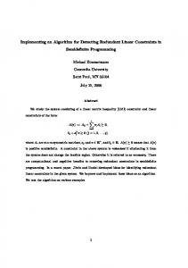
In Fig. 6 the BER per layer are shown for a system with nT = 4 and nR = 4 antennas when the “genie” detection is used. In every detection step k = 4, . . . , 1 a diversity of gd = nR −k+1 is achieved. According to the diversity levels, the BER of layer k decays with (Eb /N0 )−gd . Thus the BER of the upper layers decay much steeper due to the higher diversity levels in comparison to the layer detected first (layer 4).
In order to improve the performance of the single user to user communication, each layer is now independently encoded by a channel coder. For simplicity, we used the half rate (7, 5)oct convolutional encoder and viterbi decoding as shown in Fig. 7. Fig. 8 shows the Frame Error Rate (FER) of an
Pseudo inverse Unsorted QRD SQRD V-BLAST
10
−2
10
Transmitter −3
10
Data
Receiver
FEC
c1
FEC
c2 cnT
−4
10
FEC
−5
0
30
VI. Applying Channel Coding
0
10
10
25
Fig. 6. “Genie” detection in a system with nT = 4 and nR = 4 antennas, uncoded QPSK symbols
−4
10
10
∼ ( Nb )−3
−5
10
BER
4 3 2 1
∼ ( Nb )−1
Pseudo inverse Unsorted QRD SQRD V-BLAST
10
Layer Layer Layer Layer
10
PSfrag replacements
10
Sfrag replacements
Sfrag replacements
0
pseudo inverse of H. The strong impact of ordering the QR decomposition is obvious and only a small difference of approximately 0.5 dB related to V-BLAST for a BER of 10−5 is visible for the SQRD algorithm. 0
5
2
4
6
8
10 Eb N0
12
in dB
14
16
18
Fig. 5. Simulation with nT = 4 and nR = 6 antennas, uncoded QPSK symbols, spectral efficiency of 8 Bit/s/Hz
In [9] the “genie” detection process was introduced to investigate the error propagation of VBLAST. This implies real interference suppression for each layer, but for subsequent layers ideal detection of the signals of preceding layers is assumed. Thus, only correct values are subtracted to reduce the system order and consequently no error propagation takes place.
20
x1
H
x2
Detector & Decoder
rec. Data
xnR
Fig. 7. Coded LST architecture with nT transmit and nR receive antennas, FEC in each layer
uncoded and a coded system equipped with nT = 8 and nT = 12 antennas using the V-BLAST or the SQRD detection algorithm, respectively. The transmitted QPSK signals are organized in frames of length L = 100 symbols including tail symbols for the coded case. The figure shows the expected performance enhancement for coded systems and again the SQRD detection nearly reaches the error probability of V-BLAST. This statement is confirmed by the simulation result for a system with nT = 4 and nR = 6 antennas,
4TH INTERNATIONAL ITG CONFERENCE ON SOURCE AND CHANNEL CODING, BERLIN, JANUARY 2002
0
10
Sfrag replacements
– as stated in Fig 2 – needs
uncoded SQRD uncoded V-BLAST coded SQRD coded V-BLAST
fV−BLAST = 8 n4T + 16 n3T nR + 8 n2T nR + 18 LnT nR (19) floating point operations. Using the same counting, the SQRD algorithm needs
−1
10
fSQRD
FER
Sfrag replacements
−2
10
0
=
12 n2T nR − 2 nT nR + nT (20) 2 +L (4 nT + 8 nT nR + 2 nT )
operations. The computational requirements of the V-BLAST and the SQRD algorithm are compared by the quotient ρ=
−3
10
6
2
4
6
8
10 Eb N0
12
in dB
14
16
18
20
Fig. 8. FER of uncoded and convolutionally coded system with nT = 8 and nR = 12 antennas, frame length L = 100, QPSK symbols
fSQRD . fV−BLAST
(21)
1 0.9 0.8
shown in Fig. 9.
0.7
ρlim
0.6
0
10
0.5
ρ
uncoded SQRD uncoded V-BLAST coded SQRD coded V-BLAST
0.4 0.3
−1
10
PSfrag replacements
0.2
FER
0.1 0 0
50
−2
10
L
100
150
Fig. 10. Quotient ρ of required floating point operations for SQRD and V-BLAST with nT = 8 and nR = 12 antennas – varying frame length L −3
10
0
2
4
6
8
10
Eb N0
12
in dB
14
16
18
Fig. 9. FER of uncoded and convolutionally coded system with nT = 4 and nR = 6 antennas, frame length L = 100, QPSK symbols
20
Fig. 10 depicts the computational advantage of the SQRD algorithm over the V-BLAST algorithm for a system with nT = 8 and nR = 12 antennas. With an increasing number L of symbols per layer the quotient ρ saturates to a limit value. This value can be calculated by ρlim = lim ρ =
VII. Computational Effort The computational requirements of the proposed SQRD algorithm and V-BLAST are compared in this section. Therefore, the floating point operations of these algorithms are specified according to the system variables nT , nR and L, with L denoting the frame length (i.e. number of symbols transmitted within one layer). Real valued additions, multiplications and divisions are equally counted as one flop to obtain a single value for the computational effort. With these assumptions, the V-BLAST algorithm
L→∞
4 nT + 8 n R + 2 18 nR
(22)
and is shown in Fig. 10 as a horizontal line. Furthermore, the computational demands of VBLAST and SQRD concerning different numbers of antennas are compared. A system with L = 100 symbols per layer and a varying number of transmit and receive antennas, with nT = nR , is investigated. Fig. 11 shows the increasing computational advantage of the SQRD compared the V-BLAST algorithm for increasing number of antennas. Thus, the SQRD dramatically reduces the computational requirements for systems with larger amount of antennas.
4TH INTERNATIONAL ITG CONFERENCE ON SOURCE AND CHANNEL CODING, BERLIN, JANUARY 2002
1
Efficiency Wireless Communications Emplying MultiElement Arrays,” IEEE Journal on Selected Areas in Commununications, vol. 17, no. 11, pp. 1841–1852, November 1999. [8] G. Strang, Linear Algebra and its Applications, Harcout Brace Jovanovich College Publishers, Orlando, Florida, third edition, 1988. [9] S. B¨ aro, G. Bauch, A. Pavlic, and A. Semmler, “Improving BLAST Performance using Space-Time Block Codes and Turbo Decoding,” in IEEE Proceedings of Globecomm, San Francisco, CA, November 2000.
0.9 0.8 0.7 0.6 0.5
ρ
Sfrag replacements
0.4 0.3 0.2 0.1 0 0
7
5
10
nT = n R
15
Fig. 11. Quotient ρ of required floating point operations for SQRD and V-BLAST with L = 100 – varying nT = nR
VIII. Summary and Conclusions We have described a new detection algorithm for LST codes. The algorithm is based on the GramSchmidt algorithm for QR decomposition and requires less computational effort in comparison to the standard detection algorithm with only small degradation in error performance. We presented simulation results for several scenarios and analytically demonstrated the computational advantage of the proposed SQRD algorithm. Since the core of our algorithm consists of a sorted kind of QR decomposition, the derived algorithm is not restricted to layered space-time architectures. It can generally be used to detect vector channel systems. References [1] E. Telatar, “Capacity of Multi-antenna Gaussian Channels,” AT & T-Bell Labs Internal Tech. Memo, June 1995. [2] S. M. Alamouti, “A Simple Transmit Diversity Technique for Wireless Communications,” IEEE Journal on Selected Areas in Commununications, vol. 16, no. 8, pp. 1451–1458, October 1998. [3] V. Tarokh, N. Seshadri, and A. R. Calderbank, “SpaceTime Codes for High Data Rate Wireless Communication: Performance Criterion and Code Construction,” IEEE Transactions on Information Theory, vol. 44, no. 2, pp. 744–765, March 1998. [4] G. J. Foschini, “Layered Space-Time Architecture for Wireless Communication in a Fading Environment when Using Multiple Antennas,” Bell Labs Technical Journal, vol. 1, no. 2, pp. 41–59, Autumn 1996. [5] P. W. Wolniansky, G. J. Foschini, G. D. Golden, and R. A. Valenzuela, “V-BLAST: An Architecture for Realizing Very High Data Rates Over the Rich-Scattering Wireless Channel,” in IEEE Proceedings of ISSSE-98, Pisa, Italy, 29. September 1998. [6] D. Shiu and J.M. Kahn, “Layered Space-Time Codes for Wireless Communications using Multiple Transmit Antennas,” in IEEE Proceedings of International Conference on Communications (ICC’99), Vancouver, B.C., June 6-10 1999. [7] G. J. Foschini, G. D. Golden, A. Valenzela, and P. W. Wolniansky, “Simplified Processing for High Spectral
20