AIAA 2016-3365 AIAA Aviation 13-17 June 2016, Washington, D.C. 17th AIAA/ISSMO Multidisciplinary Analysis and Optimization Conference
Efficient Framework for Missile Design and 6DoF Simulation using Multi-fidelity Analysis and Data Fusion Nhu Van Nguyen1, Maxim Tyan2 and Jae-Woo Lee3 Department of Aerospace Info. Eng., Konkuk Univ., Korea
Downloaded by SEOUL NATIONAL UNIVERSITY on June 20, 2016 | http://arc.aiaa.org | DOI: 10.2514/6.2016-3365
Anh Bao Dinh4 Dept. of Aeronautical Eng., HCM City Univ. of Technology, Vietnam
The efficient framework is developed and proposed for a missile design and 6DoF simulation. Adaptive multi-fidelity constraints (AMC) design method is proposed to ensure the convergence of significant constraints to high fidelity results for increasing the reliability and robustness of optimal configuration at the conceptual design stage without any noticeable turnaround time. The AMC algorithm is demonstrated for two numerical examples, with savings of 58.6% and 64% high fidelity evaluations, to obtain the convergence of adaptive constraints to high fidelity results. The multidisciplinary air-to-ground missile (AGM) design optimization is selected as a case study. The reliable optimum configuration obtained from the AMC step is used to generate the aero tables for 6DoF simulation by using the data fusion and multi-fidelity analysis. The data fusion technique combine the variable fidelity analysis into a single dataset efficiently to accelerate the generation of aero tables for 6DoF simulation while maintaining the accuracy. The proposed framework will demonstrate the effectiveness and feasibility from missile conceptual design stage to accurate missile trajectory prediction to comply with the requirements reliably and robustly.
Nomenclature 𝛿𝑎 = 𝛿𝑒 = 𝛿𝑟 = AoA = CL = CD = CN = 𝐶m = M = f ,g = x = 𝜀𝑥 = Subscripts 𝑖, 𝑗 = 𝑛 = Superscripts 0 = * = L = H =
Aileron deflection angle Elevator deflection angle Rudder deflection angle Angle of attack Lift force coefficient Drag force coefficient Normal force coefficient Pitching moment coefficient Mach number Objective and inequality constraint function Design vector Stopping criteria design variable The number of constraints Current iteration Initial value Optimum value Low fidelity High fidelity
1
Assistant Professor, Aerospace Info. Eng., Konkuk Univ., Korea,
[email protected], AIAA Member. Postdoc, Aerospace Info. Eng., Konkuk Univ., Korea, tyan.maxim @gmail.com, AIAA Member. 3 Professor, Aerospace Info. Eng., Konkuk Univ., Korea,
[email protected], AIAA Senior Member. 4 Student, Aeronautical Eng., HCM City Univ. of Technology, Vietnam,
[email protected]. 2
1 American Institute of Aeronautics and Astronautics Copyright © 2016 by the American Institute of Aeronautics and Astronautics, Inc. All rights reserved.
I. Introduction
Downloaded by SEOUL NATIONAL UNIVERSITY on June 20, 2016 | http://arc.aiaa.org | DOI: 10.2514/6.2016-3365
T
HE virtual design and flight simulation for aerospace vehicles plays an extremely significant role in the innovative and new vehicle development to reduce the cost and development time from the early design stage to the later development stage. Recently, the virtual flight test results of unmanned aerial vehicles (UAVs) 1, civil aircraft2, complex aerospace system3, and regional jet aircraft4 are used for airworthiness and certification at the certain flight condition. Hence, the reliability and accuracy of analysis module, modelling and simulation of the aerospace system are required to be verified and validated by the previous flight testing and wind tunnel data before performing any new aerospace vehicle development. The MDO in Air-to-Ground Missile (AGM) conceptual design involves configuration, aerodynamics, propulsion, trajectory, weight, performance, stability and control, dynamics analysis disciplines and coupling effects. While the complexity and fidelity of MDO problems increase, the more reliable and accurate optimal configuration is obtained. However, the computational cost is dramatically increased. Hence, the low-fidelity models are widely implemented in many missile and rocket conceptual design applications. David et al. uses the fast and robust aerodynamics analysis prediction code Aerodsn and Missile DATCOM for liquid-propellant missile system design optimization5. David et al. also notes that the impractical use of CFD in the design due to the computational load 5. The Missile DATCOM is also used in the aerodynamics prediction model. The propulsion, performance, weight and trajectory analysis discipline are based on empirical relations to minimize the gross lift-off mass (GLM) of the interceptor6. Roy et al. presents the ramjet powered missile design, using a genetic algorithm to demonstrate the first comprehensive design strategy for this type of missile7,8. However, the less reliable and robust optimal missile configuration is obtained due to the low fidelity analysis at the conceptual design stage. Hence, the multi-fidelity analysis is required to use at the early design stage to enhance the design results. Therefore, adaptive multi-fidelity constraints (AMC) for an efficient multidisciplinary missile design framework is proposed to implement the high-fidelity analysis for refining significant low-fidelity constraints in a multidisciplinary environment. The optimal missile configuration result is enhanced by performing the variable fidelity analysis, ensuring that the adaptive multi-fidelity constraints converged into the highfidelity analysis results. The adaptive multi-fidelity constraints method for missile design optimization yields worthy and more reliable design results for ensuring the satisfaction of significant constraints than the low-fidelity analysis models with low turnaround time at the conceptual design stage. In addition, the next level of design stage is to verify the optimal missile performance trajectory reliably and accurately to access on the system performance. The accurate and full aerodynamics database is required to construct for the reliable and high fidelity 6DoF simulation to access on the missile trajectory performance reliably and robustly. The most critical parts in the virtual flight certification framework are aerodynamic data tables and the reliable 6DoF simulation due to the computational burden and the non-linear dynamics of aerospace vehicles. Da Ronch et al. presented an effort to generate the efficient aerodynamic tables using the computational fluid dynamics (CFD), low fidelity analysis and basic data fusion techniques. The aerodynamic table results are compared to the wind tunnel test data of transonic cruiser concept design, an unconventional configuration, two passenger jet aircraft, and a jet trainer aircraft9. Ghoreyshi et al. introduced the approach to accelerate the generation of aerodynamic tables by using CFD, Aircraft DATCOM, and Kring for efficient flight simulation10,11. The 6DoF simulation solvers are composed of many commercial programs such as Xplane-Laminar Research12, PREPAR3D-Lockheed Martin13, PRESAGIS14, and CADAC++15 and the open source program such as FlightGear16 and AVDS- rassimtech17. However, the construction of aerodynamic tables for the AGM is extremely challenging due to the flight conditions including wide range of Mach number, angle of attack, and angle of sideslip, and control surfaces deflections including aileron, rudder, elevator, and high lift devices deflections. Hence, the computational burden is extremely challenging to construct fully accurate and efficient aerodynamic database (AeroDB) for the flight simulation. Therefore, the efficient framework for missile design and 6DoF simulation using multi-fidelity analysis and data fusion is proposed and developed. The framework is composed of the efficient design process and 6DoF simulation for the optimum missile configurat ion using the multi-fidelity analysis and data fusion to accelerating the design and aerodynamic table construction while maintaining the accuracy and reliability of framework. The numerical examples are presented to demonstrate the effectiveness and accuracy of proposed framework. The air-to-ground missile (AGM) is selected for the proposed framework in the design and 6DoF simulation stage.
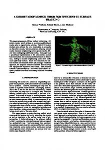
II. Efficient Framework for Missile Design and 6DoF Simulation The efficient framework for missile design and 6 DoF simulation is presented in the Figure 1. It includes the Stage 1 and Stage 2. The Stage 1 is an efficient missile design framework developed by authors for enhancing the inaccurate low fidelity constraints prediction by proposing the adaptive multi-fidelity constraints (AMCs) algorithm18. The convergences of low fidelity constraints into the high-fidelity constraints are obtained from AMCs algorithm to 2 American Institute of Aeronautics and Astronautics
Downloaded by SEOUL NATIONAL UNIVERSITY on June 20, 2016 | http://arc.aiaa.org | DOI: 10.2514/6.2016-3365
enhance the optimal AGM configuration compared to the low fidelity analysis only. The AMC algorithm is demonstrated for two numerical examples, with savings of 58.6% and 64% high fidelity evaluations, to obtain the convergence of adaptive constraints to high fidelity results18. The integrated AGM analysis and design is developed to perform the optimization of AGM. The Stage 1 is most completed in the separate published article 18. The optimal AGM configuration is used to construct the accurate AeroDB for a reliable 6 DoF simulation in the next Stage 2.
Figure 1 Efficient framework for missile design and 6dof simulation
The accurate and efficient AeroDB construction method for reliable 6DoF simulation is introduced in the Stage 2 as shown in the Figure 1. The adaptive DoE, data fusion techniques and multi-fidelity analysis are used to generate the comprehensive AeroDB for the high fidelity 6DoF simulation. The high fidelity 6DoF simulation is constructed by using CADAC++ to generate the trajectory and static missile simulation results15. The control, guidance, seeker, targeting, propulsion and intercept modules of a similar generic air-to-ground missile are used for the 6DoF simulation while the AeroDB is constructed for two sets: Low fidelity analysis-Missile DATCOM and multi-fidelity analysis 3 American Institute of Aeronautics and Astronautics
including CFD and data fusion techniques. The missile trajectory and static outputs are compared to show the efficiency and accuracy of stage 2.
III. STAGE 1: Efficient Missile Design Framework
Downloaded by SEOUL NATIONAL UNIVERSITY on June 20, 2016 | http://arc.aiaa.org | DOI: 10.2514/6.2016-3365
A. Step 1: AGM Database The AGM database is collected and divided into configuration, engine type, weight, performance and other categories. The one of interest to the AGM model is selected as a baseline to proceed to the next step. In addition, the AGM database plays an important role in evaluating the optimal AGM configuration and avoiding the strange design results. B. Step 2: AGM Configuration Designer The AGM configuration designer is developed with a user-friendly GUI in the CATIA environment to display the effective AGM model. The AGM baseline model is selected for creation in the AGM configuration designer. The CATIA displays AGM baseline and exports all of the necessary AGM configuration data to Step 4. C. Step 3: AGM Formulation The design formulation and AGM trajectory requirement must be defined to perform the AGM conceptual design optimization. D. Step 4: Integrated AGM Analysis & Design The integrated AGM analysis and design tool, that includes aerodynamics, propulsion, weight, trajectory, dynamics and S&C estimation modules, is developed and validated16. The detailed development and validation of this tool is presented in the next section. This step begins the analysis by using the AGM configuration output from Step 2. The optimizer is implemented to seek for the first optimal AGM configuration by using the design formulation and required AGM trajectory, as shown in Figure 6. E. Step 5: High-fidelity Analysis Solver The ANSYS Fluent is used as a high fidelity analysis solver to check the multi-fidelity constraints. The pitching control effectiveness, normal force, axial force coefficient and lift over drag ratio on the first optimal AGM configuration are determined in this step to check for the multi-fidelity constraint violation, as shown in Figure 6. If the constraint violation check fails, return to Step 3 to re-constrain by using the adaptive constraints framework, as addressed in section 2. The constraints are adapted until the framework convergence criteria are obtained. The adaptive constraint converges into the high fidelity constraint value. F. Step 6: Optimal AGM Configuration The optimal AGM configuration is the final iteration result of the adaptive constraints framework. The convergent history is presented for optimization and the adaptive constraint framework process. G. Step 7: High-fidelity Validation The final step is to validate the aerodynamics, stability and control characteristics of the optimal AGM model when comparing with the low-fidelity analysis results.
IV. STAGE 2: Accurate and Efficient AeroDB for Reliable 6DoF Sim A. Step 8: Adaptive DoE The adaptive DoE algorithm is developed to generate the efficient and accurate AeroDB for 6DoF simulation by using the multi-fidelity analysis. The efficient sampling points are screened and provided to perform analysis for obtaining the force and moment components of AGM as shown in Figure 1. B. Step 9: Multi-fidelity Analysis The multi-fidelity analysis is composed of the Missile DATCOM and CFD-ANSYS Fluent for generating the analysis at the given sampling points set as previous step for the optimum configuration. The verification of Missile DATCOM and ANSYS-Fluent is validated in the AGM design stage 1. The roles of multi-fidelity analyses at the stage 2 are used to generate the AeroDB for 6 DoF simulations. 4 American Institute of Aeronautics and Astronautics
Downloaded by SEOUL NATIONAL UNIVERSITY on June 20, 2016 | http://arc.aiaa.org | DOI: 10.2514/6.2016-3365
C. Step 10: Data Fusion The data fusion techniques are composed for basic data fusion and advanced data fusion techniques developed by authors. The data fusion techniques are developed by implementing the multi-fidelity analyses to minimize the uses of high-fidelity while maintaining the accuracy of models in the entire design space. The basic data fusion, namely enhanced multi-fidelity models (EMFM) was developed for a 3 DoF guided missile by using Kring model 19. The advanced data fusion techniques are composed of modified variable complexity modeling (MVCM)20 and global variable fidelity modeling (GVFM)21,22. These techniques are integrated into Stage 2 to construct the efficient and accurate AeroDB for the AGM 6 DoF simulations. D. Step 11: AeroDB Construction The AeroDB is constructed for the six basic components as 𝐶𝐿 , 𝐶𝐷 , 𝐶𝑌 , 𝐶𝑙 , 𝐶𝑚 , 𝐶𝑛 = 𝑓(𝛼, 𝑀, 𝛽, 𝛿𝑐𝑠 ) as shown in Table 1 by using the multi-fidelity analysis. The variations of angle of attack, Mach number, sideslip angle, and control deflections are sampled by the adaptive DoE techniques, then performing the multi-fidelity analysis to construct the Table 1. The longitudinal and lateral dynamic stability coefficients are processed from the six basic components to provide for AGM 6 DoF simulations. Table 1 Basic force and moment components
E. Step 12: 6DoF Simulation The AGM 6DoF simulation is based on the CADAC++ software for 6DoF missile simulations. The components of a 6 DoF simulation is shown in Figure 2. The full and accurate aerodynamic component is replaced by the full AeroDB generated from the adaptive DoE and multi-fidelity analyses. The high fidelity 6DoF simulation for AGM is programmed in C++ taking advantage of object-oriented programming techniques. The architecture of CADAC++ is based on the hierarchical structure of inherited classes15. The control, guidance, seeker, targeting, propulsion and intercept modules are referred from the similar generic air-to-ground missile. The only aerodynamic module is changed in the 6DoF simulation. In addition, the Monte Carlo Simulation (MCS) is available to analyze the miss distance by considering the uncertainty in the inputs of aerospace system.
Figure 2 Components of 6DoF AGM simulation15
5 American Institute of Aeronautics and Astronautics
F. Step 13: SIM Results The 6DoF simulation results of AGM is composed of missile static outputs and trajectory plots. The missile trajectory comparison results are presented for the two different AeroDB which are only Missile DATCOM and multifidelity analysis.
Downloaded by SEOUL NATIONAL UNIVERSITY on June 20, 2016 | http://arc.aiaa.org | DOI: 10.2514/6.2016-3365
V. Air-to-Ground Missile Case Study A. Verification of Proposed Frameworks 1. Stage 1: Adaptive Multi-fidelity Constraints (AMCs) demonstration Minimize: 𝑓(𝑥) = 𝑥1 + 𝑥2 Subject to: 𝑥12 𝑥2 𝑔1 (𝑥) = −1 20 (𝑥1 + 𝑥2 − 5)2 (𝑥1 − 𝑥2 − 12 )2 𝑔2𝐻 (𝑥) = + −1 30 120 𝑥1 (4𝑥2 ) 𝑔2𝐿 (𝑥) = + −3 20 5 80 𝑔3 (𝑥) = 2 −1 𝑥1 + 8𝑥2 + 5 𝑥𝐿𝑜𝑤 = [0; 0], 𝑥𝑈𝑝 = [10; 10] Initial point: 𝑥 0 = [5; 5] and stopping criteria: 𝜀𝑥 = 10−2 Table 2 Numerical example 1 results
Iterations 𝑔𝐻 evaluation 𝑔𝐿 evaluation 𝑓 evaluation Optimum (x1,x2) 𝑓∗
AMC method 11 12 166 166 (3.1133, 2.0634) 5.1767
Figure 3 Final iteration of design space exploration
Direct Opt. 1 29 0 24 (3.1139, 2.0626) 5.1765
Savings (%) 58.6% -
Figure 4 Convergence history
Results of the numerical problem are shown in Table 1. The solution converged in 11 iterations. As seen from the results table, the number of high fidelity constraint evaluations by the AMC method is significantly reduced, with 58.6% savings in high fidelity evaluation while maintaining accuracy compared with the direct optimization solution as shown in Table 1. 6 American Institute of Aeronautics and Astronautics
From Figure 2, it can be seen that the final adapted constraint value at the optimum point exactly matches the value of the high fidelity constraint. The optimum solution moves along with the adapted constraint until the convergence criterion is met. Figure 3 shows that the final value of the high fidelity and adapted constraints match almost exactly after just a few iterations. The error convergence rate of design variables is linear as shown in Figure 3.
Downloaded by SEOUL NATIONAL UNIVERSITY on June 20, 2016 | http://arc.aiaa.org | DOI: 10.2514/6.2016-3365
2. Stage 1: Missile DATCOM and ANSYS Fluent validation The AGM Kh-29 TE baseline is selected to perform the validation by using Missile DATCOM and ANSYS Fluent 1323,24. The Kh-29 TE baseline and mesh generation are generated by using the configuration designer mentioned in Step 2, as shown in Figure 10. The launching altitude and speed are, respectively, 10 000 meters and Mach of 1.36.
(b) Kh-29 TE baseline mesh
(a) Kh-29 TE baseline
Figure 5 Kh-29 TE missile baseline configuration
(a) Normal force coefficient
(b) Axial force coefficient
(c) Pitching moment coefficient Figure 6 Comparison of Missile DATCOM and CFD at different deflections
7 American Institute of Aeronautics and Astronautics
Downloaded by SEOUL NATIONAL UNIVERSITY on June 20, 2016 | http://arc.aiaa.org | DOI: 10.2514/6.2016-3365
The normal, axial force and pitching moment coefficient validations of AGM Kh-29 are performed by using the high-fidelity analysis solver ANSYS Fluent 13 for un-deflected control surfaces and a 10 degree pitching deflection angle, as shown in Figure 11. The normal and axial force coefficients are very close to the high fidelity analysis results for an un-deflected control surface configuration. However, the pitch moment coefficient appears in the gap while the angle of attack increases. The normal force coefficient is well-predicted by Missile DATCOM when compared with the high-fidelity analysis results at the 10 degree pitching deflection control surface. The axial force and pitching moment coefficient show a bigger gap when the angle of attack increases at the pitching deflection angle of 10 degrees. However, the trend of the axial force and pitching moment is still captured by using Missile DATCOM. In addition, the pitching control effectiveness, using high fidelity analysis and Missile DATCOM, presents the same reasonable trend; while the angle of attack increases, the pitching control effectiveness reduces. However, the high-fidelity analysis result shows more conservative results than Missile DATCOM. It is critical for an air-to-ground missile to have a sufficient pitching moment to perform the mission. Therefore, the adaptive constraints framework is applied to this air-to-ground missile design to enhance the optimal AGM results at the conceptual design stage. 3. Stage 2: Adaptive DoE demonstration The 2-Dimmensional Forrester function is selected to demonstrate the adaptive DoE techniques as shown in the Figure 7 and below equations. The Forrester surface is composed many local optimum points and flat area. The global optimum point is located at the near design space bounds in the Figure 7. The number of initial samples: 10, 20, 30 samples are selected to test the proposed adaptive DoE. The three initial samples are converged into the close final sample points as 70, 72, and 71 final sample points as shown in the Table 2 to represent the complex 2-Dimmensional Forrester function.
Figure 7 2-Dimmensional Forrester function
Convergence criteria: 𝜎̅ ≤ 0.5 and maximum sampling points 𝑛𝑚𝑎𝑥 ≤ 100
8 American Institute of Aeronautics and Astronautics
100.00 10 samples 20 samples 30 samples
Downloaded by SEOUL NATIONAL UNIVERSITY on June 20, 2016 | http://arc.aiaa.org | DOI: 10.2514/6.2016-3365
Average variance
10.00
1.00 0
20
40
60
80
0.10 Number of samples Figure 8 Adaptive DoE for 2D Forrester function convergence
4. Stage 2: Data fusion techniques demonstration One-dimensional function proposed by Forrester25 is used for numerical demonstration. This function has number of properties that make it difficult for solving using variable fidelity methods. High fidelity function has two local minimum points. Location of global optimum of high and low fidelity functions is different and direction of gradient leads to local optimum point at most part of the design space. High fidelity function: 𝑓ℎ𝑖𝑔ℎ (𝑥) = (6𝑥 − 2)2 𝑠𝑖𝑛(12𝑥 − 4) Low fidelity function: 𝑓𝑙𝑜𝑤 (𝑥) = 𝐴𝑓ℎ𝑖𝑔ℎ (𝑥) + 𝐵(𝑥 − 0.5) − 𝐶 Here the parameters A, B and C can be varied to change the fidelity of the low fidelity function. In current problem the values used are: 𝐴 = 0.5, 𝐵 = 10, 𝐶 = −5. The advanced data fusion techniques including MVCM20 and GVFM21 are proposed by authors to efficiently use the low and high fidelity analysis to construct the scaled function. Number of warm up iterations for MVCM algorithm is two. Number of DOE points for GVFM initialization is three. Table 3 One-dimensional numerical example results
Convergence Iterations 𝑓ℎ𝑖𝑔ℎ eval. 𝑓𝑙𝑜𝑤 eval. 𝜌𝑓𝑖𝑛𝑎𝑙 ∆𝑓𝑖𝑛𝑎𝑙 𝑥∗ 𝑓(𝑥 ∗ ) Global error, % Local Error, %
Mult. Local 18 37 180 -2.189 1.0e-4 0.1429 -0.986 61.0 3.1e-2
VCM Add. Global 11 23 153 0.796 4.0e-4 0.7574 -6.020 1.5e-2 1.5e-2
Hybrid Global 11 23 123 -0.305 1.0e-4 0.7570 -6.0207 2.5e-2 2.5e-2
Mult. Global 12 15 132 1.0035 1.4e-2 0.7573 -6.020 5.2e-3 5.2e-3
AVCM Add. Local 6 9 94 1.0481 4.5e-2 0.1426 -0.986 61.1 1.0e-3
Hybrid Local 7 10 79 0.8906 1.4e-2 0.1426 -0.9863 60.9 1.0e-3
9 American Institute of Aeronautics and Astronautics
Mult. Global 7 11 114 1.288 4.0e-3 0.757 -6.020 4.8e-3 4.8e-3
GVFM Add. Global 5 9 80 0.987 4.5e-2 0.757 -6.020 5.2e-3 5.2e-3
Hybrid Global 6 10 123 1.013 4.0e-3 0.757 -6.020 5.2e-3 5.2e-3
Downloaded by SEOUL NATIONAL UNIVERSITY on June 20, 2016 | http://arc.aiaa.org | DOI: 10.2514/6.2016-3365
(b) MVCM
(a) VCM
(c) GVFM Figure 9 Final state of 1D optimization example
B. Case Study: Air-to-Ground Missile (AGM) Design and Simulation 1. Stage 1: Optimal AGM configuration The optimal AGM configuration is obtained by using the AMCs algorithm from Stage 1 is shown in Figure 10.
Figure 10 Comparison of AGM configuration
10 American Institute of Aeronautics and Astronautics
More reliable and efficient results compared with the optimal AGM configuration that used the low-fidelity analysis only, through the convergence of the adaptive longitudinal control effectiveness constraint to the high fidelity results in the AMC method with low turnaround time at the conceptual design stage18. The optimal AGM configuration is used for Stage 2. 2. Stage 2: AGM 6DoF SIM AeroDB format The calculation range to construct the AGM AeroDB is shown in the Table 4. The parameters are composed of Mach number, angle of attack, sideslip angle, rudder, elevator, and aileron deflection angles. The basic static force and moment coefficients are required to construct with the given limits in the Table 4.
Downloaded by SEOUL NATIONAL UNIVERSITY on June 20, 2016 | http://arc.aiaa.org | DOI: 10.2514/6.2016-3365
Table 4 Calculation range of AGM configuration
Parameters M AoA (deg.) β (deg.) 𝛿𝑟 (deg.) 𝛿𝑒 (deg.) 𝛿𝑎 (deg.)
Low limit 0 -20 -20 -15 -15 -15
Values 6 values (step of 0.2) 20 values (step of 2 deg.) 3 values (step of 10 deg.) 0 0 0
Upper limit 1.4 20 20 15 15 15
The 1D table AGM aerodynamics table for 6DoF simulation is generated as shown in the Table 5 from the initial AeroDB in Table 4. The processed methods are developed to convert from the AGM static stability coefficient into the dynamic stability coefficients as shown in Table 5. Table 5 1D table for AGM aerodynamics database
M M M M M M M M M
1D table 𝐶𝑎0 𝐶𝑎𝑎 𝐶𝑎𝑑 𝐶𝑛𝑑𝑞 𝐶𝑙𝑚𝑑𝑞 𝐶𝑙𝑚𝑞 𝐶𝑙𝑎𝑝 𝐶𝑙𝑙𝑑𝑝 𝐶𝑙𝑙𝑝
Explanation Axial force coefficient Axial force derivative of alpha (per deg.) Axial force derivative of control fin deflection (per deg2) Normal force derivative of elevator (per deg.) Pitching moment derivative of elevator (per deg.) Pitching moment damping derivative (per deg.) Roll moment deriv of alpha^2 when phi is non-zero (per deg2) Roll moment deriv of aileron deflection (per deg.) Roll moment damping derivative (deg.)
The 2D table AGM aerodynamics database is composed of Mach number, angle of attack, and stability coefficients shown in Table 6. The processed methods are developed and coded to convert from the initial AeroDB from Table 4 for 2D AGM aerodynamics table into Table 6. Table 6 2D table for AGM aerodynamics database
M M M M M M
2D table AoA 𝐶𝑛0 𝐶𝑛𝑝 AoA AoA 𝐶𝑙𝑚0 𝐶𝑙𝑚𝑝 AoA 𝐶𝑦𝑝 AoA 𝐶𝑙𝑛𝑝 AoA
Explanation Normal force coefficient Correction to normal force coefficient when phi is non-zero Pitching moment coefficient (ignition c.g.) Correction to pitching mom coefficient when phi is non-zero Side force coefficient correction when phi is non-zero Yaw moment coefficient correction when phi is non-zero
3. Optimal AGM configuration aerodynamics using multi-fidelity analysis The optimal AGM configuration aerodynamics are performed by Missile DATCOM and ANSYS Fluent. The hybrid mesh is generated for the optimal AGM configuration for efficient computation and accurate results as shown in the Figure 11. Pointwise v.17.0 is used for the mesh generation26. The high-fidelity analysis ANSYS Fluent 14.0 is used for the analysis27. The total cells are 7.5 millions which are a optimum for the efficient computation and accurate predictions for the missile aerodynamic characteristics. 11 American Institute of Aeronautics and Astronautics
Downloaded by SEOUL NATIONAL UNIVERSITY on June 20, 2016 | http://arc.aiaa.org | DOI: 10.2514/6.2016-3365
Figure 11 Hybrid mesh of optimal AGM configuration
In hybrid mesh configurations for optimal AGM configuration, the initial cell height from the surface is set to 0.00347 m, which corresponds to a y+ value of 1.0 based on a mean aerodynamic length of 0.43 m. The wall y+ contours are resolved the missile surface as shown in the Figure 12 for the accurate missile aerodynamic coefficients prediction.
Figure 12 The wall y+.
4. Stage 2: AGM trajectory simulation The optimal AGM trajectory is simulated by using the Missile DATCOM only as shown on the Figure . The comparison of two AeroDB sets will be included into the presentation. The air-to-ground missile AGM 66 Maverick seek, control, guidance, propulsion system, and intercept module are referred to construct the optimal AGM trajectory
12 American Institute of Aeronautics and Astronautics
Downloaded by SEOUL NATIONAL UNIVERSITY on June 20, 2016 | http://arc.aiaa.org | DOI: 10.2514/6.2016-3365
Figure 13 Optimal AGM trajectory from reliable 6DoF simulation
VI. Conclusion The efficient framework for missile design and 6DoF simulation using multi-fidelity analysis and data fusion is developed and applied successfully for improving the performance of the air-to-ground baseline missile. The stage 1 is composed of the developed AMCs algorithm to converge the low fidelity constraints into high fidelity constraints for enhancing the optimal AGM configuration. The adaptive DoE, data fusion techniques are developed and validated with the numerical examples to construct the efficient and accurate AGM AeroDB by using the multi-fidelity analysis. The reliable 6DoF simulation is performed by executing the two AeroDB sets: Missile DATCOM and multi-fidelity analysis will be included to demonstrate the efficiency and feasibility of proposed framework for the new and innovative aerospace vehicles development with the robust and reliable process and evaluation methods.
Acknowledgments This work was supported by the National Research Foundation of Korea (NRF) [grant NRF2014R1A2A2A01003833] funded by the Korean government (MSIP)and the 2014 KU Brain Pool (Konkuk University).
References 1 Webster, M., Cameron, N., Fisher, M. & Jump, M. Generating Certification Evidence for Autonomous Unmanned Aircraft Using Model Checking and Simulation. J. Aerosp. Inf. Syst. 11, 258–279 (2014). 2 Liu, F., Wang, L. & Tan, X. Digital virtual flight testing and evaluation method for flight characteristics airworthiness compliance of civil aircraft based on HQRM. Chin. J. Aeronaut. 28, 112–120 (2015). 3 XU, H., LIU, D., XUE, Y., ZHOU, L. & MIN, G. Airworthiness Compliance Verification Method Based on Simulation of Complex System. Chin. J. Aeronaut. 25, 681–690 (2012). 4 Mendonça, C. B. de, Silva, E. T. da, Curvo, M. & Trabasso, L. G. Model-Based Flight Testing. J. Aircr. 50, 176–186 (2013). 5 Riddle, D. B., Hartfield, R. J., Burkhalter, J. E. & Jenkins, R. M. Genetic-Algorithm Optimization of Liquid-Propellant Missile Systems. J. Spacecr. Rockets 46, 151–159 (2009). 6 Zeeshan, Q., Yunfeng, D., Nisar, K., Kamran, A. & Rafique, A. Multidisciplinary Design and Optimization of Multistage Ground-launched Boost Phase Interceptor Using Hybrid Search Algorithm. Chin. J. Aeronaut. 23, 170–178 (2010).
13 American Institute of Aeronautics and Astronautics
Downloaded by SEOUL NATIONAL UNIVERSITY on June 20, 2016 | http://arc.aiaa.org | DOI: 10.2514/6.2016-3365
7 Hartfield, R., Jenkins, R. & Burkhalter, J. in 42nd AIAA Aerospace Sciences Meeting and Exhibit (American Institute of Aeronautics and Astronautics). 8 Hartfield, R. J., Burkhalter, J. E. & Jenkins, R. M. Scramjet missile design using genetic algorithms. Appl. Math. Comput. 174, 1539–1563 (2006). 9 Ronch, A. D., M. Ghoreyshi & Badcock, K. . On the generation of flight dynamics aerodynamic tables by computational fluid dynamics. Prog. Aerosp. Sci. 47, 597–620 (2011). 10 Ghoreyshi, M., Badcock, K. J. & Woodgate, M. A. Accelerating the Numerical Generation of Aerodynamic Models for Flight Simulation. J. Aircr. 46, 972–980 (2009). 11 Ghoreyshi, M. et al. Framework for Establishing Limits of Tabular Aerodynamic Models for Flight Dynamics Analysis. J. Aircr. 48, 42–55 (2011). 12 X-Plane 10 Global | The World’s Most Advanced Flight Simulator. X-Plane. 13 Lockheed Martin - Prepar3D. Available at: http://www.prepar3d.com/. (Accessed: 25th April 2016). 14 Presagis COTS Modeling & Simulation Software | Presagis. Available at: http://www.presagis.com/. (Accessed: 25th April 2016). 15 Zipfel, P. H. CADAC: Multi-use Architecture for Constructive Aerospace Simulations. J. Def. Model. Simul. Appl. Methodol. Technol. 9, 129–145 (2012). 16 FlightGear Flight Simulator | sophisticated, professional, open-source. 17 Rassimtech.com. Available at: http://www.rassimtech.com/. (Accessed: 25th April 2016) 18 Nguyen, N. V., Tyan, M., Jin, S. & Lee, J.-W. Adaptive Multifidelity Constraints Method for Efficient Multidisciplinary Missile Design Framework. J. Spacecr. Rockets 53, 184–194 (2016). 19 Daeyeon, L., Nhu Van, N., Tyan, M., Sangho, K. & J-W, L. Enhanced Multi Fidelity Analysis Method Using Global Exploration and Krigng Modeling. Proc. Inst. Mech. Eng. Part G J. Aerosp. Eng. 20 Nguyen, N. V., Tyan, M. & Lee, J.-W. A modified variable complexity modeling for efficient multidisciplinary aircraft conceptual design. Optim. Eng. 16, 483–505 (2014). 21 Tyan, M., Nguyen, N. V. & Lee, J.-W. Improving variable-fidelity modelling by exploring global design space and radial basis function networks for aerofoil design. Eng. Optim. 47, 885–908 (2015). 22 Maxim, T., Nguyen, N. V. & Lee J-W. A Flying Wing UCAV Design Optimization Using Global Variable Fidelity Modeling. in 11th WCSMO (Springer, 2015). 23 http://en.wikipedia.org/wiki/Kh-29 24 http://eng.ktrv.ru/production_eng/323/513/514/ 25 Forrester, A. I. J., Sóbester, A. & Keane, A. J. Engineering design via surrogate modelling: a practical guide. (J. Wiley, 2008). 26http://www.pointwise.com/ 27http://www.ansys.com/Products/Fluids/ANSYS-Fluent
14 American Institute of Aeronautics and Astronautics