directional couplers or balanced signal splitters/adders using quarterwave transmission line sections.
0 IEE 2002
19 J u b 2002
i..,
Electronics Letters Online No: 20021119 Dol: lO.I049/el:20021119
J. Chramiec (Gdynia Maritime University, Department of Marine Radioelectronics, 81 -225 Gdynia, Poland ) D
M. Kitlinski (Gdansk University of Technology, Faculty oj' Electronics, Telecommunication and Informatics, 80-952 Gdansk, Poland ) "
E-mail:
[email protected]
- x
a X
c
References 'Meander-line and hybrid meander-line transformers', IEEE Trans. Microw. Theory Tech., 1973, 21, (2), pp. 69-75 2 MATTHAEI, C L., YOUNG, L., and JONES, E.M.T.: 'Microwave filters, impedance-matching networks and coupling structures' (McGraw-Hill, New York, 1964) 3 HP Eesof, Libra v. 6.1, 1996 4 CHRAMIEC, J., and K I T L I ~ w , M.: 'Improved modelling of chip resistors used in microwave hybrid integrated circuits'. Proc. 7th lnt. Conf. Mixed Design of Integrated Circuits and Systems, Gdynia, Poland, July 2000, pp. 249-252 5 CHRAMIEC, J., and PIOTROWSKI, J.K: 'Novel approach to the characterization of coaxial-to-microstrip transitions'. Proc. 27th Europ. Microwave Conf., Jerusalem, September 1997, pp. 697-702 1
CRISTAL, E.C.:
Eigenvalues of pyramidal waveguides M. Hamid and A.K. Hamid Various attempts to detemiine the eigenvalues of a pyramidal waveguide and the assumptionsmade in each case are described. Numerical comparison between the eigenvalues for the lowest-order mode is also presented.
C
b X
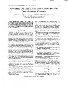
Fig. 1 Schematic diagram of three pyramidal waveguides with d@erent H-plane walls a Classical Hamngton geometry h First proposed simplified geometry c Second proposed simplified geometry
For TE to r modes, the mode functions are given by
Introduction: One o f the most common techniques for analysis of the radiation characteristics of pyramidal horn antennas is the aperture field method which employs the fields in the transverse cross-section of a pyramidal waveguide at the aperture plane. Harrington [l] formulated this problem as a sectoral section of the spherical space (0 5 $ 5 $ 1 ) between a wedge and two conducting cones (8,5 8502), i.e. as the space bounded by two coaxial cones and a cylindrical wedge as shown in [l]. This resulted in the aperture shown in Fig. la where the H-plane curved walls OAB and OCD are convex and concave, respectively, and lie on the two spherical cones 0 = 0, & O2 while the flat E-plane walls AC and BD are at x = 0 & 29,. This led to an exterior formulation with very complicated eigenvalue equations in terms of spherical wave and associated Legendre functions summarised as follows. For TM to r modes, the mode functions are given by
(Fr)u" = [L"(cos 0) ' dL;(-
cos O,)/dO, - Lf(- cos
e)
x dLf(cos U,)/d0,]. cos(w4) . ff;')(kr)
(4)
where the eigenvalues 11 must be such that the Neumann boundary condition is satisfied on the conical walls and are hence found from the roots of the equation: dL:(coS V,)/dOz . dLr(-
COS B,)/dQl
- dLp(-
COS @,)/do,
dL?
x (cos B,)/d8] = 0
(5)
The functions L t ( u ) denote an arbitrary solution to the associated Legendre equation ]L = 0,
ti=
cos(0)
(6) and hence where u and o are nonintegral in general. Here w is evaluated from the boundary conditions on the flat vertical walls, so that p = 1 , 2 , 3 , .. .
0=pn/d,,
(2)
while the eigenvalues u must be such that the Dirichlet boundary condition is satisfied on the two conical walls and are hence found from the roots of the equation:
[L:"(cosB,)L$(-
COSQ,)
- l y - cos e,)Lp(cos SI)] = 0
ELECTRONICS LETTERS
5th December 2002
(o- u - l)L:+,(u)
+ (2u + l ) u L f ( u ) - (w + n)Lf-,(u) = 0
(7)
Since Harrington was not able to solve for the eigenvalues u against mode number p , an approximate solution based on the same formulation was later derived by Narasimhan [2]. Narasimhan proposed asymptotic values in order to initiate an iterative solution which leads to the exact numerical values of the eigenvalues. His asymptotic expression for the associated Legendre hnction is given by
(3)
Val. 38 No. 25
LT(cos 8) = J,(uQ),
m = 1,2, 3 . . .
(8)
1685
where
u = [s(s
+ 1)]05,
s = -0.5
+ [0.25 + (p,,/ao)*]O
(9)
and wherep,, are tabulated and are set by the boundary conditions and the mode number, while cto = (0, - 01)/2 is half the flare angle between the coaxial conical walls. For 41=45" Narasimhan plotted his asymptotic and exact values of s for the fundamental TE and TM modes as shown in Fig. 5 of [2]. Our main purpose in this Letter is to present a simplified analysis of the problem by using an interior instead of Harrington's exterior formulation. Thus, instead of first satisfying the E-plane boundary conditions at Q = Q 1 and then at Q = Q 2 , we satisfy both conditions simultaneously by measuring 8 off the waveguide axis since cos 0 is the same at 0 = fxo. This results in the interior space bounded by a cone and a wedge as shown in Fig. Ib. Here the H-plane walls (OAB and OCD) are convex and part of the same cone while the E-plane walls (OAC and OBD) are flat and form part of a wedge the edge of which is perpendicular to the axis of the cone. The resulting eigenvalue equation is (cos 0) = 0 or d c (cos 0) = 0 at 8 = fm0 for the TM and TE modes, respectively. Since w is already known, the eigenvalues u are obtained by following the procedure of Hamid [3] for the eigenvalues of a conical hom where
e
larly since it also corresponds to the actual geometry of pyramidal waveguides which are truncated to produce pyramidal horn antennas. As expected, the agreement of Narasimhan with the two simplified models improves as the flare angle increases since the curved walls in such cases approach the flat walls geometry.
Acknowledgment: The authors wish to acknowledge the financial assistance of the Faculty of Graduate Studies of the University of South Alabama and the University of Sharjah.
0 IEE 2002 Electronics Letters Online No: 20021 166 DOI: lO.I049/el:20021166
M. Hamid (Department of Electrical and Computer Engineering, University of South Alabama, Mobile, Alabama 36688, USA) A.K. Hamid (Department of Electrical and Electronics Engineering, University of Sharjah, RO. Box 27272, Sharjah, UAE) References 1
(10)
O h
=pnJ4,,
p = 1 , 2 , 3 , .. .
= gn/2ct0,
= i,2,3,
(11)
... ,
=
= [s(s + 1)lo5 (12)
where the subscripts e and h denote the E- and H-planes, respectively. A comparison with the eigenvalues 's' of Narasimhan for the fundamental mode corresponding to the special case of 41 = 45" is shown in Table 2.
Table 1: Resulting eigenvalues 's' for dominant TM and TE modes compared with Narasimhan [2]
55" 60"
7.930
8.938
5.660
5.165
3.660
3.655
3.220
3.234
2.880 2.610
2.891 2.604
I
I
I
Conclusion: Examination of our numerical results indicates that the eigenvalues for the four flat wall model is sufficiently simple and accurate compared with Narasimhan's complicated results, particu-
1686
'Time-harmonic electromagnetic fields' (McGraw-
'Eigenvalues of a class of spherical wave functions', IEEE Trans. Antennas Propag., 1973, AP-21, (I), pp. 8-14 3 HAMID, M.: 'Diffraction by a conical horn', IEEE Trans. Antennas Propag., 1968, AP-16, ( 5 ) , pp. 520-528 4 BARROW, W.L., and CHU, L.J.: 'Theory of the electromagnetic hom', Proc. IRE, 1939, 21, pp. 5 1-64 5 HAMID, M , and HAMID, A.K : 'On the eigenvalues of pyramidal hom antennas'. URSI Dig., 2002, USNCJURSI National Radio Science Mtg, San Antonio, TX, USA, June 2002, p. 34 NARASIMHAN, M.s.:
MMIC power amplifier with on-chip bias current controlling circuit for W-CDMA mobile handset Youn S. Noh, Ji H. Kim, Joon H. Kim and Chul S. Park A new on-chip bias current controlling circuit for efficiency enhancement has been devised and implemented to a W-CDMA InGaP/GaAs HBT MMIC power amplifier. It supplies a quiescent current of 86 (54) mA for a high (low) power mode operation. The reduced
quiescent current at the low power mode operation improves the PAE as much as 21.6% at the output power of 20 dBm and 59.2% under 0 dBm output power compared to the high power mode operation only.
Total flare angle Narasimhan (exact value of s) Proposed solution 18" 8.625 9.512 20" 1.937 8.513 5.660 5.520 30"
I
HARRINGTON, R.F.:
Hill, 1961), pp. 281-283
2
The resulting eigenvalues 's' for the dominant TM and TE modes are presented and compared with those of Narasimhan in Table 1. A further simplification of the problem is to view the pyramidal waveguide as bounded by four flat walls as the case in practice. Here the interior space is bounded by the intersection of two cylindrical wedges the edges of which are perpendicular to each other resulting in a rectangular cross-section with four flat walls as shown in Fig. I C . The resulting eigenvalues are denoted by wh and o, in the H- and E-planes, respectively, and are given as [4, 51
12 September 2002
Introduction: Wideband-CDMA is one of the leading standards for the 3G wireless communication systems and adopts spectrally efficient hybrid phase shift keying (HPSK) as a digital modulation scheme. But HPSK has inevitably a non-constant envelope, requiring both high linearity and efficiency at the same time. Power amplifiers need high efficiency characteristics over a wide output power range for the W-CDMA system, and the most probable output power is not a maximum output power but ranges from -20-20 dBm. A back-off of the output power to the most probable output power provides a significant decrease in efficiency. The techniques drawing high efficiency around the most probable output power range are emerging as one of the most significant issues in designing mobile handset power amplifiers. To increase the PAE at the low output power level, there were several reports using DC-DC converters [l-31. However, integrating the DC-DC converter for a variable bias supply results in a significant increase of the chip size and cost, which make the DC-DC converter not suitable for the mobile handset power amplifiers. In this Letter, a new MMIC power amplifier is described, which is implemented with on-chip bias control circuit switching the quiescent current level between high and low power mode. The amplifier is operated in a class AB (near class B) mode at the high (low) output power level. The near class B operation at the low output power level improves the PAE effectively with the reduced quiescent current. Bias current controlling circuit: Biasing at the low quiescent current for the HBT power amplifier is the most basic method for high
ELECTRONICS LETTERS 5th December 2002
Vol. 38 No. 25