solid stereo 3D image or may experience eye strain and headaches. Stereo fusion problems increase simulator sickness especially with a head-coupled display ...
Evaluating Dynamic-Adjustment of Stereo View Parameters in a MultiScale Virtual Environment Isaac Cho, Jialei Li, Zachary Wartell Charlotte Visualization Center, University of North Carolina at Charlotte
ABSTRACT Dynamic view parameter adjustment can reduce visual fatigue issues in stereo displays. In a multi-scale virtual environment, which has geometric details ranging over several orders of magnitude, these adjustments are particularly important. We evaluate how two adjustment techniques interact with 7 degree-offreedom navigation in desktop VR and a CAVE. The travel task has two stages, an initial targeted zoom and detailed geometric inspection. The results show benefits of the adjustments both for reducing fusion problems and for task completion time, but only in certain condition combinations. Peculiar view configuration examples show the difficulty of creating robust adjustment rules. Keywords: stereoscopic display, navigation Index Terms: K.6.1 [Management of Computing and Information Systems]: Project and People Management—Life Cycle; K.7.m [The Computing Profession]: Miscellaneous—Ethics 1
INTRODUCTION
Stereoscopic head-coupled display can enhance depth perception of the user in a computer generated 3D world [9]. However, sometimes the user sees two separate 2D images rather than a solid stereo 3D image or may experience eye strain and headaches. Stereo fusion problems increase simulator sickness especially with a head-coupled display. Many factors influence stereo fusion problems, but typically these translate into a range of distance in front of and behind the screen where a stereo 3D image can be comfortably fused. Fusion problems are particularly problematic in a multi-scale virtual environment (MSVE) which is a virtual environment (VE) that contains geometric details whose sizes cover several orders of magnitude. The interaction (stereo × MSVE) occurs because viewing the small details in the MSVE often requires scaling up the world to the point where the rest of the VE geometry extends far behind and in front of the display screen. In non-MSVE environments whose geometry has a simpler geometric distribution [34] stereo adjustment techniques are relatively easier. A traditional VE usually requires 6 degree-of-freedom (DOF) view control for 3D interaction techniques (IT) such as selection, manipulation and travel. In MSVEs, however, when a 3D user interface (UI) supports direct 3D manipulation, stereo or headcoupled display, the 3D UI benefits from an additional view scale factor in the view model [22] [23]. Proper choice of view scale-and often its dynamic adjustment--is important for reachability during direct manipulation, for maximizing effective stereopsis and for optimizing head-coupled structure-from-motion cues. Adding the 7th DOF, however, can complicate user navigation and also increases the chance for novice users to produce imagery with stereoscopic fusion problems (for example by abrupt manual enlargement of the scale factor). This paper evaluates the effect of three different stereo autoadjustment conditions on a dual stage, multi-scale travel task * email address IEEE Symposium on 3D User Interfaces 2014 29 - 30 March, Minneapolis, Minnesota, USA 978-1-4799-3624-3/14/$31.00 ©2014 IEEE
using a one-handed scene-in-hand [33] travel technique. One adjustment condition is an auto-scale adjustment. Ware et al. [36] introduces this as cyclopean scale with the scale’s center between the eyes. A question is how does an auto-scale adjustment to control fusion problems interact with a user’s MSVE travel task when it requires her to reach a particular view scale--not just a particular view pose. Two possibilities are: P1) Auto-adjusting view scale may help because novice users may find purely manual control of 7DOF travel difficult and automation might reduce the difficulty. P2) Auto-scale adjusting might hurt by tending to set the view scale to a scale other than the one the user desires. This question appears to have not been empirically evaluated. Our third auto-adjustment condition is an auto-translate, a modification of Wartell et al. [36]. This condition is included because while it does perform some auto-adjustment (which might reduce novice user’s difficulty compared to purely manual 7DOF travel), it does not alter the view scale, possibly avoiding interfering with the user control of scale. Finally, our experiment uses an extensive MSVE, one whose database requires out-of-core paging (see Figure 5 and Figure 6). Such environments have zoomable geometry throughout the VE rather than just at a few select locations. Prior authors often use the latter to demonstrate multi-scale travel techniques to avoid having to implement or leverage an out-of-core renderer. Results show benefits of the adjustments for task completion time and for reducing fusion problems, but only in certain combinations of display and task stage conditions. The autoadjustments were only beneficial when working at a certain range of target view scale during the first stage zoom-in. Results were positive for desktop VR but not for a CAVE leading to several lessons learned regarding porting desktop VR techniques to a CAVE. Finally, using an extensive MSVE reveals view configuration examples that require display system specific modifications and demonstrate the importance of testing autoadjustments for MSVE travel within an extensive MSVE with formal trials that require many different travel paths. 2
RELATED WORK
Head-coupled displays display 3D graphics where the generated perspective graphics image is dynamically adjusted based on head (or possibly more directly eye pupil) position. Head-mounted displays (HMDs) mount the displays on a headset or helmet. In contrast in Head-Tracked Displays (HTDs), the display is stationary mounted on a desk (desktop VR), a table (the virtual workbench) or one or more walls (the CAVE). We define stereoscopic 3D displays as a particular sub-class of true 3D displays [10] that generate one or more pairs of optically planar images. For stereo displays, four eye separations can be distinguished. Eye separation can be measured in either physical coordinates or virtual coordinates. The latter accounts for the 3D view (isotropic) scale factor [22]. Further, there is the user’s true eye separation (i.e. her inter-pupillary distance) versus the modeled eye separation, the value used in the view frustum geometry. As an example, assume the 3D view scale used is 1/106 so that a virtual Earth of approximate diameter 106 m is rendered at a diameter of 1 m and assume the human subject has a physical true separation of 6 cm while the physical modeled eye separation
91
is set to 3 cm. Then the virtual true separation is 60 km and virtual modeled separation is 30 km. This is example is a case of false eye separation. The modeled eye separation is deliberately set to a value other than the true value for purposes of distorting the depth of the presented stereo 3D image. Human interocular distance varies subtly with vergence movements, but false eye separation is a technique that assigns modeled eye separation a value whose difference from the true value (modeled_eye_separation – true_eye_separation) is significantly larger than that occurring due to vergence movements. False eye separation distorts the 3D stereo image. The modeled 3D image is the displayed virtual 3D scene accounting for the view scale. An Earth globe (roughly 106 meters in diameter), might appear as a modeled 3D image of 1 m in diameter given a view scale of 1/106. The perceived 3D image is the stereo image the user perceives. There are numerous ways to operationally define the perceived image [31] [6]. Here perceived image means the expected result of performing a registration experiment [4] between the synthetic image and a physical pointer under the further assumption stereopsis works like a theoretic range finder. 2.1 Stereoscopic Fusion Problems Fusion problems in stereoscopic displays have been studied in stereo media [17] [27] and computer graphics [9] and continue to be investigated [25]. Barring dynamically adjusting the optical focal depth [10], for an (optically planar) stereoscopic 3D display fusion problems are managed in one of three ways: dynamic stereo depth range adjustment using geometric distortions, clipping out unfusible geometry, or simulating image blur due to depth-of-field. A common stereo image depth adjustment method that pre-dates computer graphics is deliberate altering the modeled eye separation (or camera separation). It is generally accepted that the perceived 3D image depth range need not be equal to the model 3D depth range for stereo to enhance depth discrimination. Further ortho-stereo (view scale = 1 with no other distortion) is not necessary for many classes of applications. Microstereopsis [26] is an interesting, if extreme, example. (For a review of the relation between VR application considerations and stereo distortion effects see Wartell et al. [34]). Underestimated modeled eye separation (e.g. using 3 cm instead of 6 cm) can compress the perceived 3D image depth nonlinearly to reduce stereo fusion problems. The distortion is more specifically a non-affine homology [35]. Setting the modeled to the true separation while creating only a virtual-to-physical difference is equivalent to applying a uniform scale transform to the perceived image and this technique also predates computer graphics. Ware et al. [32] develop the latter into the cyclopean scale, a dynamic adjustment where the VE is dynamically scaled with the scale’s fixed point between the stereo centers of projection. Wartell et al. [34] classify 9 prior fusion control methods including perceived image depth adjustments and clipping plane methods, circa 2001. They abstract fusion control characteristics and match them to various application characteristics. Prior methods have a static or dynamic model of the near fusible distance (nf) and farthest fusible distance (ff) relative to the display screen. They compute a nearest point (np) and/or farthest scene point (fp) which are typically the nearest and farthest visible pixels. Dependent on the number of free parameters in a given adjustment technique, the adjustment could map np to nf , fp to ff or both. Later Wartell [34]presents a new 2 parameter method capable of mapping both. Holliman et al. [8] present an adjustment technique which allows a defined region of interest in scene depth to have an improved perceived depth representation compared to other
92
regions and which can keep this mapping constant even if total scene depth is changing. They also present a novel three-region algorithm for stereoscopic image adjustment. Lambooij et al. [14] review the concept of visual fatigue to clarify the importance of various causes and aspects of visual comfort in relation to stereoscopic display and image generation. They indicate that even within the sufficient range allowing for satisfactory depth perception provided by one degree limit of disparity, visual discomfort may still occur due to the factors: (1) excessive demand of accommodation-convergence linkage, (2) 3D artifacts resulting from insufficient depth information in the retinal images yielding spatial and temporal inconsistencies, and (3) unnatural amounts of blur. Carvalho et al. [2] dynamically adjust stereo parameters based on a CubeMap structure [18] during the usage of two VR tools, fly and examine, in a MSVE. Panum’s fusion area increases with lower frequencies which occur with blurring [3] and since the pin-hole camera model commonly used for interactive rendering has no depth blurring, the zone of single vision in the virtual environment will be thinner than in the physical environment. Hillaire et al. [7] demonstrate real-time depth-of-field added to a non-stereoscopic 3D game. They use precise gaze tracking to determine the screen gaze point and the depth buffer to determine the simulated depth-of-field’s focal plane. Sun et al. [29] compare fixed and dynamic depth-offield simulations with a fixed and dynamic 2 parameter stereo depth adjustment. Users generally preferred the dynamic conditions over the fixed conditions, but unlike prior work users did not rate the DOF conditions highly. Leroy et al. [16] use an image process approach to blur area of high horizontal parallax. They use a highly rigorous series of stereo vision tests and show that adding their blur filter approach reduces both subjective measures and physiological measures of eye strain. However, the simulated depth of focus was fixed at the display plane. Collectively these results indicate that if gaze based, real-time depth-of-field were implemented with stereo, eye strain would be reduced and users would accept and prefer DOF simulation. However, without a gaze based implementation users appear to object to the simulated DOF. Likely it will interfere with complex 3D tasks requiring fixating on, selecting and interacting with geometry over the wide depth ranges as occurs in real-world 3D environments and certainly in multi-scale ones. We believe the ultimate stereo fusion control approach will combine gazed tracked DOF as well as stereo depth adjustment. However, the primary goal of this paper is to investigate the interaction of autoscale and auto-translate on 7DOF travel tasks. 2.2 Multi-Scale Virtual Environment Not all 3D UIs for MSVEs support view scale as 7th DOF because their underlying view model lacks the required sophistication [22]. Instead, “zooming-in” occurs through 6DOF view adjustment (dollying) with some auto-adjustment applied to travel velocity and possibly to the near/far clipping planes to manage zbuffer precision. However, early VR work [22] demonstrates various 7DOF travel techniques as well as the benefit of view scale differences in multi-user VEs [15]. (This had been observed for 2D multi-user environments earlier [13]). Various previous works use specific navigation techniques for MSVEs. Pierce and Pausch [20] propose a travel technique for better scalability to large virtual world, with visible landmarks allowing users to travel in the vicinity with a single gesture and with symbolic place representations allowing users to travel to distant locations with a small number of gestures. Houtgast et al. [11] (elaborated in Wartell et al. [37]) develop a virtual workbench application which balances interaction and stereoscopic display for a multi-scale volumetric weather
visualization. They find a trade-off between direct manipulation and stereoscopic display, which must be optimized to help users perceive the environment. Their techniques rely on user created volumes-of-interest to drive auto-scaling. Kopper et al. [12] present the design and evaluation of two navigation techniques for MSVEs. They find that automatic scaling is more efficient than manual scaling and target-based navigation performs better than steering-based navigation. Wu et al. [38] present the design and evaluation of way-finding aids in a MSVE. The result of their experiment that compares three different aids interface (view-in-view map, animation guide and human system collaboration) shows that the view-in-view map offers the best performance overall. Bacim [1] designs a framework for navigation techniques that provide understanding and classification of way-finding information (hierarchical and spatial information) needed for travelling in a MSVE. Experiments show that the new techniques help users perform better in both travelling and way-finding. Trindade et al. [30] improve to two existing interfaces in order to assist and facilitate navigating a MSVE. For flying they include support for collision handling and automatic navigation speed adjustment with respect to scale. For exo-centric travel, they use a point-of-interest technique with an automatic pivot point based on the construction and maintenance of a CubeMap. Their techniques improve the execution of navigation tasks. Oh and Hua [19] present a user study on three multi-scale visualization interfaces on a 3D workbench display: focus plus context, fixed focus plus context, and overview plus detail, with the purpose of identifying the differences of these interfaces with two tasks (path following and 3D map reading) in large scale information visualization on the 3D workbench. 3
DYNAMIC-STEREO ADJUSTMENT TECHNIQUE
Our experiment compares three stereo adjustment conditions: no adjustment, auto-translation (AT) and auto-scale (AS). This section describes the adjustments and justifies their design. 3.1 Stereo Adjustment Conditions Stereo adjustments with 2 parameters can map both the nearest scene point (np) to the nearest fusible point (nf) and the farthest scene point (fp) the farthest fusible point (np) [34]. However, we choose auto-adjustments that each only have 1 parameter. This means that in any given circumstance, our auto-scale and autotranslate conditions must choose to adjust for either the near fusion limit or far fusion limit. but they cannot adjust for both. The AS and AT conditions are built on prior adjustments reviewed below using a nearest fusible distance violation example. AS uses a cyclopean scale [32]. For a near fusion violation, cyclopean scale polls the z-buffer to determine the nearest scene point. If it extends outside the near fusible distance a cyclopean scale is perform to make the near point fusible (transition indicated by red arrow in Figure 1A). AT uses a translation [36]. The z-buffer is polled to determine the nearest scene point. If it extends outside the near fusible distance, a view translate is performed perpendicular to the scene (transition indicated by the red arrow in Figure 1B). We compare the AT condition to the AS condition because while AT does perform some auto-adjustment (which might reduce novice user’s difficulty compared to purely manual 7DOF travel), it does not alter the view scale, possibly avoiding interfering with the user control of scale. The translation takes 0.5s to avoid abrupt stereo depth changes and user dis-orientation. In order to control possible simultaneous violations of the near and far fusion points, AS and AT conditions would need to be combine their basic transform (scale/translate) with an additional
(A) (B) Figure 1: Stereo adjustment techniques. (A) Auto-adjustment of view scale: the system pushes the Earth’s toward the screen with preserving the retinal angle and projected image size. (B) auto-adjustment of the view location: the system translates the Earth toward the screen while preserving view scale.
(A) (B) Figure 2: Illustration of dynamic adjustment steps. (A) If the np is closer from the eye position than the NearW TD, the system relocates the point to the Near TD. (B) If the np is further than the Far TD, then the system relocates the point to the Far TD.
view parameter adjustment. Options include false eye separation among others [34]. We chose to not incorporate an additional parameter and technique, because we argue the issue whether the stereo auto-adjustments interfere or aid 7DOF travel (P1 and P2) is best evaluated using auto-scale and auto-translation alone. Combining auto-scale or -translate with another parameter would raise the question of (1) which additional technique to add and (2) whether any observed effects on 7DOF travel are due to: the scale vs. translate alone, the particular secondary parameter/technique chosen, or differing interactions between this additional technique and auto-scale versus auto-translate. Figure 2 illustrates our AT condition’s complete algorithm. Near Target Distance (TD) is a static approximation of the nearest fusible distance. Far TD is a static, very conservative approximation of the far fusible distance. A z-buffer method determines the nearest point, np, in the scene. If np < NearTD we translate perpendicular to the screen to bring np to NearTD (Figure A). If np > FarTD we adjust to bring np to FarTD (Figure B). Implicitly, if np is in the range [NearTD, FarTD], no adjustment occurs. This leads to a “buffer zone” such that if the nearest point is in the zone, no auto-adjustment occurs during user scene manipulations. Note, we do not compute the farthest scene point. This means once the user zooms in (via view scale) far geometry can exceed the far fusion limit. However, the FarTD check does avoid far fusion problems due to the nearest scene point being too far away. Anecdotally we found this occurred frequently during 7DOF travel in our experiments’ MSVE. Our AS condition works similarly substituting cyclopean scale for the translation. Finally the geometry sampled from the zbuffer purposefully excludes the 3D cursors that represent the input devices. The 3D cursors which are allowed to appear at any screen parallax. Handling the cursors this way proved necessary for our 3D cursor based travel technique. Because the AS and AT conditions do not include 2 autoadjustable parameters, our conditions will generate more fusion issues than if they did incorporate a further parameter. We assume that in a deployed application an additional parameter (or perhaps gazed-tracked depth-of-field) would be added for additional auto-
93
(A) (B) Figure 3: Auto-stereo adjustment problem 1 (continuous adjustments)
(C)
adjustment and we do not promote the AS and AT conditions complete fusion control solutions. For the experimental reasons detailed above our conditions employ scale and translate alone. 3.2
Dynamic-Adjustment Stereo View Parameter Technique Problems This section discusses cases where we discovered auto-stereo adjustment techniques can be problematic. The first problem is an undesired continuous scale adjustment. In this scenario, the usability issues are (1) the adjustment moves a geometry target that the user is trying to advance to away from the user and (2) the adjustment does not switch off in a reasonable amount of time. In Figure 3A, the red dot is the nearest point in the view frustum. The green polyline is some terrain and the blue box is an object the user desires to inspect. The system changes the scale factor to adjust the near point to the Near TD. After the first adjustment, the system detects the new nearest point of the scene (the blue dot in Figure 3B) and the system does a second adjustment. After the second adjustment, the depth buffer detects the new nearest point (the red dot in Figure 3C) and does a third adjustment. Therefore, the system will keep doing the adjustment until no pixel is in front of the Near TD and meanwhile the blue box, an object of user interest, keeps getting push further away. By itself this can be highly irritating to the user. Further, in an MSVE which truly contains large amounts of geometry in both Gigabytes and spatialextent, such as a global terrain, if the algorithm continuously finds a new nearest point, the auto-adjustment will keep auto-adjusting. Imagine having an infinite surface or a being inside an infinite cloud of volumetric data. Under such scenarios each autoadjustment finds a new non-fusible nearest point. Much MSVE prior work does not use rendering engines that support out-of-core 3D databases. In contrast, this paper’s experiment uses a global-terrain, out-of-core database. In designing and informally testing our adjustment conditions in such an environment (Figure 5 and Figure 6), that the above scenario occasionally arose when the view overlooks the horizon. After experimenting with various approaches, we added the following rule to minimize this problem: Rule 1: If the center of the virtual Earth is out of the view frustum, then the auto-stereo adjustment technique is deactivated. To handle other special cases there are two other rules: Rule 2: If the user’s eye position is inside of the virtual Earth, then the auto-stereo adjustment technique is deactivated. Rule 3: If the user’s eye position is between the Near TD and Far TD, then the auto-stereo adjustment technique is deactivated. 4
USER INTERFACE
This section discusses our display and virtual environment. In both the desktop VR and CAVE applications the user holds a pair of button balls (Figure 4) tracked by a Polhemus Fastrak. Transparent spherical 3D cursors appear that represent each button ball. There is an offset between the button ball and the spheres. For brevity, in our further descriptions we assume the
94
Figure 4: Button Ball input devices
user is right handed. However, the UI itself accounts for the user’s handedness assigning button functionalities based on the user’s dominant and less-dominant hand. We use a one-handed travel technique. Holding one button engages a scene-in-hand technique [33]. Holding a second button engages rate controlled scaling with the center of scale is the cursor’s position when the button is first pressed [22]; a separate, small red sphere shows this point. If the cursor is inside the Earth, we compute the intersection point of a line from the eye to the cursor with the Earth and display a small sphere at that point and this point is used as the center of scale instead [37]. A third button resets the view to handle getting lost. The desktop VR system uses a 24" Samsung 2233RZ display running at 120Hz as 1680×1050 resolution with nVidia 3D Vision glasses. A Polhemus Fastrak tracks the head and buttonballs. The user is seated. A 3D cursor is displayed for each buttonball at a fixed offset, set by the user at start up. This allows the user to rest her elbows on the desk, her lap, or chair arm [24]. Based on informal pilot tests, the stereo TDs are ±8" from the screen. The CAVE system consists of three large displays (8'×6.4' physical size and 1280×1024 screen resolution each) and a Polhemus Fastrak tracker with the wide range emitter. It provides wider Field of Regard (FOR) and Field of View (FOV) than the desktop VR condition. The user stands with no place to rest her elbows or hands. The larger screen size causes the user to stand farther from the screen. This changes the fusible depth range in a non-linear fashion. For the CAVE, the TD is 48" (1.21m) for the front screen and 36( ״0.91m) for left and right screens. During the pilot testing, we found that the user tends to stand on approximately 6' (1.52m) from the center screen and 4' (1.01m) from right or left display. When the user changes her view to the left or right, she tends not to move her body. With 48 ״TDs, the AS or AT technique is deactivated because of Rule 2. We set shorter TDs, 38" (0.96m) for left and right displays than the center one based on the observation that users tend not to physically walk much during the experimental task. For the CAVE system, three displays have separate depth cameras for z-buffer sampling. Only one depth camera is activated based on the position of the center of the virtual Earth. For example, if the center of the virtual Earth is in the right screen view frustum, only the right screen’s depth camera and TDs are used for auto-stereo adjustment. Since the CAVE system has three displays for navigation, Shaw and Green’s offset, perpendicular to the screen, must be modified. We implement a short-range, non-linear offset technique that supports a cursor offset in any direction (360º) based on the Go-
Go technique [21]. The gain factor, however, is very low and allows a user 6' from the center screen to extend the 3D cursor slightly beyond the screen. Walking forward with the arm at full extent allows the 3D cursor to reach the Far TD. 4.1 Application Our application is built using osgEarth [5] and osgVE [28]. Our experiment is designed for a global, virtual Earth based on the task of visiting a place of interest, such as a famous city, country or landmark, and then inspecting details of the region. Therefore, we defined the first task as finding a target box which is randomly located on the virtual Earth (Figure 5A). The box appears at one of four different sizes. This condition tests for any interaction of the auto-adjustment condition with the range of view scale change required to reach the target box. To motivate participants, we use pre-defined locations of the target box at capitals or famous cities in the world. In addition, we divided the world into spatial domains by its distance from the start position (America, Africa, Asia, Australia and Europe). This maintains similar travel distance across participants and ensures each spatial domain occurs at least once per box size. A timer appears in the upper left of the screen. The user can see her best time below the timer. The current trial number is shown below the best time. The upper right of the screen displays the auto-adjustment’s engagement status as either “on” or “off”. A name of the city, which is a target box location, is displayed below the auto-adjustment engagement status. The view scale factor is displayed on the bottom right of the screen. 4.2 Experiment Design Each experimental trial involves two tasks. In Task 1, the user travels to a target box which is randomly located on the Earth. The box comes with four different sizes (see Figure 6). If a target box is too small to be seen by the user at the start position, then a red arrow, whose world coordinate size is dynamic to maintain a roughly constant screen space size, indicates the target box location (Figure 6A and Figure 6B). The user must travel (pose and scale) to position the box within a screen centered wireframe box (Figure 5A). After the user finishes Task 1, the target box disappears and four numbered boxes appear that indicate four cardinal directions; they are the same size as the target box (Figure 5B). Each box has a small hole on one face and a tiny colored sphere inside. The sphere color (red, blue or white) matches the colors of the button ball’s buttons (see Figure 4). The user must carefully maneuver to see the sphere color through the hole. The user indicates the sphere color by pressing the corresponding button on the left button ball. The user examines the boxes in order of their number labels. A success sound plays when the user presses the correct colored button. After the user presses the correct button for all four boxes, a new trial begins. As Section 4 explains, the user can reset the view position to the initial position by pressing a button of the right button ball during a trial if lost. For Task 1, the initial position is where the user can see the entire virtual Earth (Figure 6). For Task 2, the initial position is the last position where the user finished Task 1. We used a simpler docking task to train participants on how to use buttonball input for the travel technique for 10 minutes. After the training, the instructor teaches the user about stereoscopic fusion problems by showing a case of extreme negative parallax. The instructor also explains how auto-stereo adjustment (AA) techniques try to minimize fusion problems. We use a within-subject design (AA × BoxSize) repeated measures ANOVA (analysis of variance) for each Task and display condition (desktop VR or a CAVE) to analyze output of our experiments. Participants need to accomplish two navigation tasks with three AA conditions: Auto-Scale (AS), Auto-
(A) (B) Figure 5: Task 1: (A) target box finding and (B) Task 2: inspection
(A)
(B)
(C) (D) Figure 6: The target box has 4 different box sizes. (A) Size 1, (B) Size 2 (C), Size 3, and (D) Size 4.
Translation (AT) and No Auto-Adjustment (NA). Each participant performs 20 trials with each AA condition. In each trial, a target box appears in a random city with random size for Task 1. Orientation of numbered boxes is also randomized per trial for Task 2. We record task completion time and number of resets for both Task 1 and Task 2. AA condition order was fully counterbalanced between subjects using Latin squares. Our primary hypotheses are: H1: AS and AT are expected to have faster completion time than NA for the both Task 1 and Task 2. This is because they partially reduce the DOFs the user must manually adjust. H2: AT is expected to have faster completion time than AS for both Task 1 and Task 2. This is because AS auto-scaling may interfere the user desired manual scale. H3: AS and AT are expected to produce less stereo fusion problems than NA for the both Task 1 and 2. 5
RESULT
We recruited 24 participants (twelve for each display condition) from the Computer Science department and the Psychology department participant pool for the experiment. All participants have (corrected) 20/20 or higher eye vision. In the desktop VR group, eight participants are CS major and four are non-CS major (eight are males, and four are females). Participants have high daily computer usage (6.67 out of 7). Nine participants have experience with 3D UIs such as Microsoft Kinect. In the CAVE group, six participants are CS major and six are non-CS major (eight are males and four are females). Participants have high daily computer usage (6.42 out of 7). Three participants have an experience with 3D UIs. We use the per-trial mean of task completion time and number of resets. The reported F tests use α=.05 for significance. The post-hoc tests that were conducted were Fisher’s least significant differences (LSD) pairwise comparisons with α=.05 level for significance. The qualitative data were analyzed by Friedman test with α=.05 level for significance. The post-hoc tests that were conducted were Wilcoxon signed-rank tests.
95
Table 1: Average of completion time (CT) and its standard deviation (SD) of auto-adjustment conditions by box sizes.
Task 1
Task 2
Box Size 1 2 3 4 Overall 1 2 3 4 Overall
CTNA 30.25 23.04 15.86 6.91 19.01 34.44 35.08 40.86 33.09 35.87
SDNA 16.93 7.79 6.33 1.96 12.96 12.04 12.61 12.95 12.05 12.39
Desktop VR CTAS SDAS 25.33 12.11 17.02 5.28 11.07 1.83 6.12 1.06 14.89 9.71 32.08 8.75 30.68 5.50 37.11 11.07 37.19 12.63 34.27 9.99
CTAT 20.66 16.57 11.00 6.63 13.71 34.53 31.90 37.50 33.00 34.23
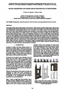
Figure 7: Completion time of box size of Task 2 (blue) in the desktop VR, and (red) in the CAVE. Error bars in the graph represent 95% confidence interval.
5.1 Quantitative Table 1 illustrates averages and standard deviations of task completion time of AA conditions by box size in both VEs. Results of ANOVA for Task 1 of the desktop VR show a main effect on completion time of AA condition (F(2,22)=5.871, p=.009, ηp2=.348). LSD tests show completion time of NA, 19s, is slower than AS (p=.015) and AT (p=.036), 14.9 and 13.7s. However, completion times between AS and AT do not differ (p=.361). In the CAVE, there is no significant main effect of AA condition for Task 1 (p=.082). There is a main effect on completion time of AA condition for Task2 of the CAVE (F(2,22)=7.624, p=.003, ηp2=.409). LSD pairwise comparisons show completion time of AS condition, 56.3s, is significantly slower than NA, 44.3s, (p=.005) and AT, 48.5s, (p=.036). However, completion times between NA and AT do not differ (p=.137). In the desktop VR, there is no main effect on completion time of AA condition for Task 2 (p=.132). The main effect of box size on completion time for Task 2 of the desktop VR is significant (F(3,33)=6.294, p=.002, ηp2=.364). This was unexpected. The target box reached in Task 1 is the same size as all those in Task 2. Therefore, little view scale change was expected. LSD comparisons show that box size 3 (M=38.5, SD=10.6) has slower completion time than box size 4 (M=34.4, SD=10.8, p=.044), 2 (M=32.6, SD=8.8, p=.003) and 1 (M=33.7, SD=9.6, p=.016) (see the blue line in Figure 7). There is a main effect of box size on completion time for Task2 in the CAVE (F(3,33)=8.918, p