Science, University. Of Southern California, 941 W. 37th Place Los Angeles, CA ..... from an experiment carried out in Echo Park lake, Los Angeles to validate the.
Experiments in autonomous navigation with an under-actuated surface vessel via the Null-Space based behavioral control F. Arrichiello, J. Das, H. Heidarsson, S. Chiaverini, G.S. Sukhatme Abstract— This paper presents an autonomous navigation technique for an under-actuated surface vessel based on the use of a behavior-based technique, namely the Null-Space based Behavioral (NSB) control. In particular, the NSB control is used to generate motion directives for the vessel in order to sequentially visit various locations in the environment, while avoiding collisions with static obstacles. To work with underactuated vessels, the NSB controller is coupled with a low-level maneuvering controller that generates the actuator forces to cause the vessel to follow the motion directives generated by the NSB. The overall control technique has been experimentally validated in the field with an autonomous under-actuated surface vessel navigating in a lake, avoiding collisions with small islands and a fountain.
I. I NTRODUCTION Marine robotics has been the object of widespread research interest in the last decades and a large body literature deals with the control of marine vehicles for autonomous navigation [11]. The interest in the field is widely motivated by the different application areas of marine robots, e.g., marine biology, harbor operations, defense and patrolling of coastal perimeters, and naval system applications. The main challenge in controlling and maneuvering marine vessels is related to both the complex nature of the marine environment due to hydrodynamic effects, and the vessel dynamics that is often under-actuated (i.e., the propulsion system cannot generate forces in all the generalized directions). These aspects result in a non-linear dynamical vessel model. Moreover, for underactuated systems, holonomic control is not possible. The control solutions proposed in the literature mostly perform tracking control along an assigned path, and dynamic positioning (i.e., keeping a predefined fixed position). Several control approaches have been presented in the literature to solve the tracking control problem and the dynamic positioning for fully actuated vessels [11], [12]. For underactuated vessels equipped with less than 3 actuators (only 1-2 actuators are used to control the surge, sway and yaw modes), maneuvering control is a challenging problem. In [16], [14], [17] the main control problems Filippo Arrichiello and Stefano Chiaverini are with the Dipartimento di Automazione, Elettromagnetismo, Ingegneria dell’Informazione e Matematica Industriale, Universit`a degli Studi di Cassino, Via G. Di Biasio 43, 03043, Cassino (FR), Italy, {f.arrichiello,chiaverini}@unicas.it, http://webuser.unicas.it/lai/robotica. Jnaneshwar Das, Hordur Heidarsson, and Gaurav S. Sukhatme are with the Department Of Computer Science, University Of Southern California, 941 W. 37th Place Los Angeles, CA 90089-0781 {jnaneshd, heidarss,gaurav}@usc.edu, http://robotics.usc.edu/resl.
regarding underactuated vessels are enumerated and partially solved, in [13] a nonlinear path-following for underactuated marine craft is presented, while in [1], [2] trajectory tracking and way-point navigation is investigated in the presence of currents and model uncertainties. In this paper we focus on navigation techniques for a realistic environment where several obstacles can be found. Thus, we make use of a behavior-based technique as a guidance control to take advantage of its reactivity to unpredicted conditions. Behavior-based approaches [9], [6], [7], widely studied for ground mobile robots, have the advantage to make the system navigable in complex and dynamically changing environments, reducing off-line path-planning. In particular, this paper presents the use of a behavior based technique called the Null-Space based Behavioral (NSB) control as a guidance system for a marine surface vessel. The NSB approach has been extensively tested for the control of autonomous ground robots and results have shown robust control both with single robots and multi-robot teams for tasks such as: an autonomous robot moving toward waypoints [4], formation and spread control for a team of robots [5], entrapping/escorting an external agent with a team of robots [3]. In this paper, the NSB technique is used as a guidance control system to provide the motion directives for an autonomous surface vessel with two goals: a) reaching several targets spread in the environment b) avoiding collisions with static obstacles. To properly follow the motion directives generated by the NSB, a maneuvering controller has been used to generate the thruster/rudder commands considering a specific under-actuated vessel. The proposed control approach has been experimentally tested in the field with an autonomous under-actuated surface vessel that had to reach several targets spread in a lake, avoiding collision with small islands and fountains. II. C ONTROL
STRATEGY
In the proposed scenario, a marine vessel was required to reach a set of targets spread in the environment, avoiding collisions with static obstacles. The motion control strategy for the vessel is decomposed into multiple control levels: • Supervisor; • NSB; • Maneuvering control. At the highest level, a supervisor chooses the target to reach based on the mission parameters, the overall map of the targets, and the current vessel position; an intermediate control level implements the NSB control to define the
motion directives for the vessel to reach the chosen target and avoid collisions with the static obstacles present in the environment; finally, a maneuvering controller commands the vessel actuators to maneuver the vessel based on the motion directives received from the NSB control. III. T HE S UPERVISOR The boat supervisor has knowledge of the overall mission of the boat. In particular, it knows the target map and keeps track of visited targets to avoid revisiting them in the course of the mission. When a new target has to be chosen, the supervisor finds the target nearest to the current position of the vessel among the non-visited targets. This information is given to the NSB controller that has to define the vessel motion directives. When a target is reached (i.e., when the distance between the vessel and the target is lower then a given threshold) a new target has to be selected. Once all the targets have been visited, the vessel is asked to reach and keep a final restore configuration. IV. T HE N ULL -S PACE
BASED
B EHAVIORAL
CONTROL
The Null-Space based Behavioral (NSB) control is a behavior-based approach aimed at controlling the motion of autonomous vehicles in dynamic scenarios. The NSB approach, extensively treated in literature by some of the authors of this paper, has been widely used to control single and multiple autonomous robots to achieve several different types of missions. Here, the NSB is used as a guidance system for a marine autonomous surface vessel that has to reach different targets while avoiding static obstacles. The basic concepts of the NSB approach are summarized below, while more details can be found in [4], [3]. The overall mission of the robot is decomposed into elementary tasks and, for each of them, a suitable task function is defined as σ = f (p)
(1)
where σ ∈ IRm is the task variable to be controlled, m is the dimension of the task function, and p ∈ IRn is the robot position. Differentiating eq. 1, we obtain: σ˙ =
∂f (p) v = J (p)v , ∂p
(2)
where J ∈ IRm×n is the position-dependent task Jacobian matrix and v ∈ IRn is the robot velocity. Notice that n depends on the specific robotic system considered. In the case of a robot modelled as a point moving on a planar surface, n = 2. The velocity reference for the robot, starting from desired values σ d (t) of the task function, acts at the differential level by inverting the (locally linear) mapping (2); this problem has been widely studied in industrial robotics (see, e.g., [18] for a tutorial). A typical requirement is to pursue minimum-norm velocity, leading (when J(q) is full rank) to the least-squares solution: � �−1 v d = J † σ˙ d = J T JJ T σ˙ d . (3)
At this point, the vehicle motion controller needs a reference position trajectory besides the velocity reference; this can be obtained by time integration of v d . However, discrete-time integration of the vehicle’s reference velocity would result in a numerical drift of the reconstructed vehicle’s position; the drift can be counteracted by a so-called Closed Loop Inverse Kinematics (CLIK) version of the algorithm, namely, � � v d = J † σ˙ d + Λe σ , (4)
where Λ is a suitable constant positive-definite matrix of e is the task error defined as σ e = σ d −σ. gains and σ Thus, for each task of the mission, a velocity reference is defined as in eq. 4. However, when the mission is composed of multiple tasks, the overall vehicle velocity is obtained by properly merging the outputs of the individual tasks. A velocity vector for each task is computed as if it were acting alone; then, before adding the single contribution to the overall vehicle velocity, a lower-priority task is projected onto the null space of the immediately higher-priority task so as to remove those velocity components that would conflict with it. Thus, by analogy with eq. (4), the single task velocity is computed as � � ei , v i = J †i σ˙ i,d + Λi σ (5)
where the subscript i denotes i-th task quantities. If the subscript i also denotes the priority of the task with, e.g., Task 1 being the highest-priority one, in the case of 3 tasks and according to [10] the CLIK solution (4) is modified into � �h � � i v d = v 1 + I − J †1 J 1 v 2 + I − J †2 J 2 v 3 , (6) � � where the I − J †i J i operator represents the null-space projector of the ith -task, i.e., it filters the velocity components that would conflict with the i-task. Moreover, the saturation technique presented in [8] has been applied to the resulting velocities in order to limit the amplitude of the velocity signals. The overall mission is decomposed in two elementary tasks, namely: • Task #1: obstacle-avoidance; • Task #2: move-to-target. a) Obstacle-avoidance Obstacle-avoidance is the highest priority task because its goal is to preserve the integrity of the vehicle. In the presence of an obstacle in the advancing direction, its aim is to keep the vehicle at a safe distance from the obstacle. Thus, its implementation produces as output a velocity, in the vehicle-obstacle direction, that keeps the vehicle at a safe distance from the obstacle. Formally: σ1 σ1,d J1
= kp − po k ∈ IR = d = rˆT ∈ IR1×2 ,
where po is the obstacle position and p − po rˆ = kp − po k
is the unit vector aligned with the obstacle-to-vehicle direction. According to (5), the primary-task velocity is then v 1 = J †1 λ1 (d − kp−po k) . In the Null-Space-based approach, moreover, the obstacle avoidance task also generates the null-space direction. The expression of the corresponding null space is ˆrˆT N (J 1 ) = I − J †1 J 1 = I − r where I is the Identity matrix of proper dimensions. It can be observed that this direction is tangent to the circle centered in the obstacle. Thus, the velocity component of the secondary task has to be projected along the tangent direction. It is worth noticing that the obstacle avoidance task is active only when required, i.e., when the vehicle is closer than a threshold value to the obstacle and when the output velocity of the lower priority tasks is in the obstacle direction. b) Move-to-target The move-to-target task output is a velocity, in the target direction, proportional to the distance from the target pg ; therefore, it is σ2 σ 2,d J2
= p ∈ IR2 = pg = I ∈ IR2×2 .
According to (5), the secondary-task velocity then is � v 2 = Λ2 pg − p . (7)
When active, the obstacle avoidance is always the primary task. Thus, the velocity reference produced by the NSB approach, depending on the distance from the static obstacles, is: v N SB
=
v 1 + N (J 1 )v 2
v N SB
=
v2
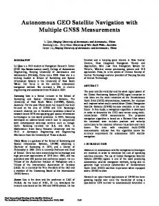
V. E XPERIMENTAL P LATFORM - USC/RESL B OAT The platform used for this experiment is an Autonomous Surface Vehicle (ASV) designed by the University of Southern California’s Robotic Embedded Systems Lab. The ASV is an OceanScience QBoat-I hull with a length of 2.13m and a width of 0.71m at the widest section. It weighs 48kgs with instrumentation and batteries. The computing package consists of a Mini-ITX 2 GHz dual-core computer for primary computation, and a Gumstix 400M Hz single-board computer for auxiliary operations related to the science package. A 28Ah sealed lead acid (SLA) battery is used to power the computer and all sensors, and a 32Ah AGM battery is used for the drive motors and the rudder. The ASV has been observed to have a nominal runtime of 6 hours. There are two modes of operation for the ASV a) The RC mode, where the operator can control the robot directly using an RC controller over a 47M Hz RC link. b) Computer Control mode - where the boat can be controlled using the
Fig. 2. The USC RESL Autonomous Surface Vehicle used for the experiments reported here.
onboard computer (or a game-console plugged into a dockcomputer). A. Actuation system The ASV has an actuation package consisting of two bidirectional thrusters and a rudder. The thrusters are driven by a Roboteq AX1500 2-channel motor controller. The rudder is controlled by a servo motor driven by RC servo receiver in the RC mode, and a serial-servo controller when in computer controlled mode. A powered winch allows raising and lowering of an aquatic sensor probe up to a depth of 25m. B. Sensor equipment The sensor suite on the ASV consists of a navigation package and a science package. The navigation package consists of a Microstrain 3DMG Inertial measurement unit (IMU), a uBlox GPS unit, and a Crossbow Dynamic Measurement Unit (DMU). The 3DMG IMU is used as a compass and a 3-axis accelerometer generating measurements at 32 Hz, the uBlox GPS provides global position at 1 Hz, and the Crossbow DMU serves as a rate gyro with a sampling rate of 120 Hz. The science package consists of a TWI wind speed and direction sensor, an Imaginex profiling sonar, and a Hydrolab MiniSonde MS-5 water chemistry sensor. The science package is used to gather weather, bathymetry, and water chemistry data from lakes and marinas. VI. M ANEUVERING
CONTROL
The maneuvering controller is an on board controller aimed at steering the vessel along a desired path and moving it with a desired velocity [11], [12]. Thus, receiving motion reference commands, the maneuvering controller has to dynamically generate the generalized forces applied by the actuators. 1) The ASV actuation system: For the vessels, the following 3 DOF nonlinear maneuvering model [11], is considered: η˙
=
R(ψ) ν
(8)
M ν˙ + N (ν)ν
=
τ + RT(ψ) w,
(9)
T argets′ M ap
Supervisor
N ext T arget
NSB
η
v NSB
τ2
=
τ3
=
•
η, ν
The surge control has to regulate the norm velocity of the vessel to the value generated by the NSB; however, the vessel has to move at full speed only when the orientation error is null. Thus, the surge control works as a PI controller regulating the advancing direction multiplied by a scaling factor depending on the orientation error. Defining δcomm = (tr + tl ),∆U = UN SB − U and ∆χ = χN SB − χ, then, � � � �4 Z ∆χ δcomm = Kp3 ∆U + Ki3 (∆U dt) cos (12) 2
χ
tr + tl
ψ
(tr − tl ) bI 2 (tr − tl ) b + αu sin(Rang ) cos(Rang )I 2
n
Heading autopilot Surge control
The heading autopilot is aimed at controlling the heading of the boat to make it moving in the desired direction χN SB . In particular, it regulates the propulsion torque and the rudder angle to correct the orientation of the vessel. Thus, defining l) δdif f = (tr −t b, then tr and tl are chosen so as 2 δdif f = Kp1 (χN SB − χ) + Kd1 r
(10)
where χ is the direction of the vessel velocity vector (see fig. 3); the rudder angle, instead, is chosen so as Rang = Kp2 (χN SB − χ) + Kd2 r.
u tl
where tr and tl are the right/left thruster forces, b is the thruster distance, I is the distance along the x axis between the thrusters force application point and the boat barycenter, Rang is the rudder angle and α is a hydrodynamic coefficient. In the proposed guidance system, the maneuvering control is a velocity and heading controller aimed at causing the vessel to follow the velocity reference commands generated by the NSB. In particular, following the schema of Figure 3, the output of the NSB is a velocity vector commands generated for a material point; then, the desired norm of velocity UN SB and heading/advancing direction χN SB can be extrapolated from the velocity vector v N SB . Following the approach proposed in [15], the maneuvering control is decomposed into: •
Vessel 1
Sketch of the guidance system control schema
where η = [n e ψ]T is the position and attitude vector in the North-East-Down (NED) reference frame; ν = [u v r]T of the ASV is the linear and angular velocity vector in the body-fixed (BODY) reference frame; R(ψ) ∈ SO(3) is the rotation matrix from NED to BODY; M is the vessel inertia matrix; N (ν) is the sum of the centrifugal and Coriolis matrix and of the hydrodynamic damping matrix; τ is the vessel propulsion force and torque; w is the vector of the environmental forces (wind, currents, etc.) acting on the vessel in the NED reference system. As described in Section V-B, the actuation system of the vessel is composed of two parallel bi-directional thrusters and a rudder. Thus, the propulsion force can be modelled as: =
τ
η, ν
η
Fig. 1.
τ1
Maneuvering c.1
(11)
β
{B}
Rang tr
U v e
Fig. 3.
Motion reference model of the surface vessel
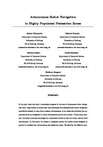
VII. E XPERIMENTAL RESULTS In this section we present the results from an experiment carried out in Echo Park lake, Los Angeles to validate the approach presented in Section V-B. The chosen area, as shown in fig. 4, is a rectangular region of about 250m (long edge) with different static obstacles (3 small islands and a fountain). The area had significant windage, with average wind velocity of 5 km/h with peaks reaching 11 km/h. The vessel autonomously navigated in the lake reaching a set of 22 targets spread in the chosen area, avoiding collision with the static obstacles. The position of the targets and of the islands/fountain were assigned in UTM coordinates, while the vessel positioning was dynamically read by the GPS sensor. The target to be reached was dynamically selected by the supervisor controller on the basis of the GPS vessel positioning, the dynamic map, and the knowledge of the visited targets.
considered reached when the vessel was within a distance of 1.5 m from it. Figure 8 shows the desired and the measured velocity of the boat during the first 300s of the experiment. The desired velocity command was saturated to 1 m/s; in particular, the saturation limit was reached each time a new target was selected.
Experiment site at Echo Park Lake, Los Angeles
When a new target has to be chosen, the supervisor finds the target nearest to the current position of the boat from the set of non-visited targets. Once the next target is decided, the NSB approach dynamically defines the motion directives of the boat to reach the target while avoiding collisions with the obstacles encountered on the path. In particular, the obstacle avoidance task function was activated only when the vessel was closer than a safety distance to the obstacles. As visible in Figure 5 the fountain was dangerous for the vessel integrity, a large circular safety zone was chosen centered between the fountain and its closest island. For the NSB approach, obstacle avoidance is the primary task when active; the NSB gains have been selected by trial and error as λ1 = 1 and Λ2 = 0.1.
Fig. 6. Path followed by the vessel during the overall experiment overlaid on on the environmental map
1.2 1 [m/s]
Fig. 4.
0.8 0.6 0.4 0.2 0
0
100
[s]
200
300
Fig. 8. Plot of the boat desired and measured velocity during the first 300s of the experiment
A video of the reconstruction from the experimental data (the data are taken from GPS and compass reading) can be downloaded at the URL: http://webuser.unicas.it/arrichiello/video/aim09 exp.mpg 100 [degree]
50
Fig. 5. Picture of the boat during a field trial with the fountain and one of the small islands in background
Figures 7-6 shows the path of the vessel during the overall execution of the experimental mission obtained by the GPS reading. The dots represent the 22 mission targets, while the circles represent the safety regions of the obstacle avoidance task function, i.e., the obstacle avoidance task function was activated only when inside the region. A target was
0 -50 -100 -150 -200 0
100
[s]
200
300
Fig. 9. Plot of the desired and measured heading during the first 300s of the experiment
100
[m]
80 60 40 20 0
STOP 50
0
100
Fig. 7.
[degree]
50 0 -50
Fig. 10.
100
[s]
200
150 [m]
200
250
200
Path followed by the vessel during the overall experiment
100
-100 0
START
300
Plot of the heading error during the first 300s of the experiment
VIII. C ONCLUSION In this paper, we presented an autonomous navigation control technique for an under-actuated surface vessel designed for marine biology and oceanography experiments. The approach, based on a behavior based technique coupled with a maneuvering controller, was experimentally tested on a small ASV in a lake in Los Angeles. The mission consisted of multiple targets and obstacles. The robot successfully navigated to all the targets while avoiding all the obstacles, validating the control approach presented in the paper. In the future we plan to use the techniques presented for large-scale biological sampling experiments at marinas and lakes with obstacles. Moreover, we plan to add current and wind compensation in the maneuvering control to properly navigate in sea environment. The illustrated experiments also represent the first step for our long-term goal; the control of a multi-robot platform for cooperative experiments. Our immediate future goal is to extend this algorithm to a multirobot setup with two robots with communication constraints. R EFERENCES [1] AP Aguiar and JP Hespanha. Trajectory-tracking and path-following of underactuated autonomous vehicles with parametric modeling uncertainty. IEEE Transactions on Automatic Control, 52(8):1362–1379, 2007. [2] AP Aguiar and AM Pascoal. Dynamic positioning and way-point tracking of underactuated AUVs in the presence of ocean currents. International Journal of Control, 80(7):1092–1108, 2007.
[3] G. Antonelli, F. Arrichiello, and S. Chiaverini. An experimental study of the entrapment/escorting mission for a multi-robot system. IEEE Robotics and Automation Magazine (RAM). Special Issues on Design, Control, and Applications of Real-World Multi-Robot Systems, 15(1):22–29, March 2008. [4] G. Antonelli, F. Arrichiello, and S. Chiaverini. The Null-Spacebased Behavioral control for autonomous robotic systems. Journal of Intelligent Service Robotics, 1(1):27–39, online March 2007,printed January 2008. [5] G. Antonelli, F. Arrichiello, and S. Chiaverini. Experiments of formation control with multi-robot systems using the null-space-based behavioral control. IEEE Transactions on Control Systems Technology, in press, 2009. [6] R.C. Arkin. Motor schema based mobile robot navigation. The International Journal of Robotics Research, 8(4):92–112, 1989. [7] R.C. Arkin. Behavior-Based Robotics. The MIT Press, Cambridge, MA, 1998. [8] F. Arrichiello, S. Chiaverini, P. Pedone, A.A. Zizzari, and G. Indiveri. The null-space based behavioral control for non-holonomic mobile robots with actuators velocity saturation. In Proceedings 2009 IEEE International Conference on Robotics and Automation, pages 4019– 4024, Kobe, J, May 2009. [9] R.A. Brooks. A robust layered control system for a mobile robot. IEEE Journal of Robotics and Automation, 2:14–23, 1986. [10] S. Chiaverini. Singularity-robust task-priority redundancy resolution for real-time kinematic control of robot manipulators. IEEE Transactions on Robotics and Automation, 13(3):398–410, 1997. [11] T.I. Fossen. Marine Control Systems: Guidance, Navigation and Control of Ships, Rigs and Underwater Vehicles. Marine Cybernetics, Trondheim, Norway, 2002. [12] T.I. Fossen. A nonlinear unified state-space model for ship maneuvering and control in a seaway. Journal of Bifurcation and Chaos, 2005. [13] T.I. Fossen, M. Breivik, and R. Skjetne. Line-of-sight path following of underactuated marine craft. In Proceedings 2003 IFAC Conference on Maneuvering and Control of Marine Craft, Girona, Spain, September 2003. [14] E.L. Lefeber, K.Y. Pettersen, and H. Nijmeijer. Tracking control of an underactuated ship. IEEE Transactions on Control Systems Technology, 11(1):52–61, 2003. [15] A. Pereira, J. Das, and G.S. Sukhatme. An experimental study of station keeping on an underactuated ASV. In 2008 IEEE/RSJ International Conference on Intelligent RObots and Systems, pages 3164–3171, Nice, France, Sept. 2008. [16] K.Y. Pettersen and T.I. Fossen. Underactuated dynamic positioning of a ship- experimental results. IEEE Transactions on Control Systems Technology, 8(5):856–863, 2000. [17] K.Y. Pettersen, F. Mazencs, and H. Nijmeijer. Global uniform asymptotic stabilization of an underactuated surface vessels: Experimental results. IEEE Transactions on Control System Technology, 12(6):891– 903, 2004. [18] B. Siciliano. Kinematic control of redundant robot manipulators: A tutorial. Journal of Intelligent Robotic Systems, 3:201–212, 1990.