Fast lifting wavelet transform and its implementation in Java Jan Maly \ Pavel Rajmic^ Bmo University of Technology, Faculty of Electrical Engineering and Communication, Department of Telecomunications, Purkynova 118, 61200 Bmo, Czech Republic
[email protected], raimic(glfeec.vutbr.cz
Abstract Fast lifting wavelet transform is a technique which replaces standard discrete wavelet transform used in computation of wavelet coefficients. The idea of lifting comes from the lifting scheme, a method used in wavelet design. The standard method relies on convolution of the original signal with FIR filter structures. Fast lifting scheme basically breaks up the original filters into a series of smaller structures, providing a very sophisticated and versatile algorithm that is up to 50 % faster than the standard way with no extra memory requirements. This paper discusses an implementation of this algorithm in Java language, comparing both speed and efficiency of standard and fast lifting wavelet transform for CDF 9/7 filters, which are used in lossy image compression in JPEG2000 standard. Java has been chosen for its platform independent character and easy integration in mobile devices.. Keywords: Fast, lifting, wavelet, transform, convolution, Java, CDF
1 Introduction The discrete wavelet transform has lately gained significance in many signal applications, including analysis and compression. Lossy image compression standards based on DWT alow us to benefitfi*ommuch better compression efficiency and many interesting features, such as progressive codec behavior or supression of blocking artifacts. Anyway, these depend heavily on a choice of wavelet coefficients coding (typical representatives are vector-based methods - Embedded Zerotree Wavelet [3] and Set Partitioning in Hierarchical Tress [4] and scalar EBCOT - used in JPEG2000 standard). All of these features need a versatile and fast DWT coder and decoder; without that component in the coding chain, no efficient implementation could ever be proposed. This problem is much more relevant in any application which lacks computation power and need to use as little memory, as possible. A typical representative of such an application is a mobile device - such as a standard today's cell phone. Although it is generally possible to improve existing hardware architecture to contain support for DWT directly (specific realizations were proposed for this purpose, exploiting many interesting hardware features such as parallel processing Please use the following format when citing this chapter: Maly, J., Rajmic, P., 2007, in IFIP International Federation for Information Processing, Volume 245, Personal Wireless Communications, eds. Simak, B., Bestak, R., Kozowska, E., (Boston: Springer), pp. 488-496.
Personal Wireless Communications
489
[1]), sometimes it is cheaper and more desirable to implement this feature by software. Mobile devices do integrate support for Java^^ Virtual Machine, making it easy to write platform-independent programs. In the following paper, we will analyze the efficiency of CDF 9/7 filter fast lifting wavelet transform realization and compare it to standard convolutional approach. But first we need to focus on the theory beyond the lifting scheme.
2 Discrete wavelet transform Proposed by [5], discrete wavelet transform consists of analysis (wavelet coefficients computation) and reconstruction (signal re-assembly) stage. Both stages incorporate filtering with two adjacent FIR structures, the high pass (h) and low-pass (/) filters. Analysis filters are formed by a pair (h, g), synthesis (reconstruction) filters are described by a pair (h, g). Every set of coefficients created by analysis is a subject of subsampling (removing even results), so every stage produces exactly half the amount of source data. This process meets the Nyquist's rule, as long as half of the frequencies have been discarded in every filtering step. At the synthesis stage, zeros must be inserted consequently before filtering steps (Fig.l). If within this scheme perfect reconstruction is archieved (which is an essential condition for successful compression), we call the filter pair (h, g) complementary.
Fig. 1: DWT stages description, x is the input signal, y stands for wavelet coefficients, x' is the reconstructed signal 12 a x2 blocks represent the subsampler and upsampler, respectively.
2.1 Perfect reconstruction, polyphase matrices The perfect reconstruction is archieved by satisfying the following set of conditions [6]:
h{z)h{z-')~g{z)giz~')^2 h{z)h{-~z-') + g{z)g{^z'')
=Q
(1)
490
PWC 2007
To understand the problem more, we need to define a polyphase representation of the filters defined in the form of polyphase matrix, a 2x2 transform matrix that treats the odd and even samples independently. Polyphase matrix for synthesis is defined as
P{z) =
(2)
where hg and hg are defined as even and odd samples of h, that is (3) The same principle as (3) applies to g^ and go coefficients. We can also define analysis polyphase matrix In a very simmilar way:
P(z) =
(4)
For a perfect reconstruction, P{z) and P{z) must satisfy the following:
P{z)P{z-'Y =1
(5)
Based on the above formulations, discrete wavelet transform can be described in terms of polyphase matrices as
= P{z)\
z-^xXz)
(6)
for analysis and
z~^x^{z)
= P{z)\
(7)
for synthesis.
3 Lifting scheme The idea of lifting is based on the following: If a filter pair (//, g) is complementary, then for every filter s the pair (7J', g), where
Personal Wireless Communications
491
(8) is complementary, too. This rule also applies symetrically as
g'{z) = g(z) + tiz').h(z).
(9)
The principle can be reversed, so that we can explicitly say: if the filterbanks (h, g) and (h',g) allow for perfect reconstruction, then there exists an unique filter s satisfying (8). Each such transform is called a lifting step - because what we perform is lifting the values of one particular subband with the help of the other. In the language of polyphase matrices, lifting step described by (8) produces new polyphase matrix /^^'^(z), which is defined (based on (2) - [5]) as
P"''\z) =
"1 s(z) Hz). 0 1
(10)
Because we have lifted the low-pass subband with the help of the high-pass subband, this step is called primal lifting or update step. By taking (9) into consideration we can define
P"^"(z) =
1 0" -'(^). 7{z) 1
(11)
By lifting the high-pass subband with the help of the low-pass one, we have just made dual lifting or predict step (prediction of the odd samplesfi*omthe even samples). Lifting factorization [6] is a generally defined process that is used to factorize complementary wavelet filter pair into a series of lifting steps. By computing greatest common divisor {gcd) of even and odd filter values using the Euclidean algorithm, we obtain a structure consisting of subsequent pairs of primal and dual lifting steps:
1 s;(z)
p(^)=\n 0
1
1 0" 7,{z) 1
(12)
where Sj(z) and ti{z) are Laurent polynomials computed for each step z by the gcd algorithm as the resulting quotient (with the division remainder being zero). In practice, these are usually first or second order polynomials (one to three-tap FIR filters). K and \IK act as resulting stream scaling constants and can be omitted if we accept the fact of resulting coefficients being scaled.
492
PWC 2007
4 CDF 9/7 lifting implementation The most efficient CDF (Cohen-Daubechies-Feauveau wavelet) 9/7-tap lifting factorization is as follows [6] (only corresponding step factors Sj and ti from (12) are listed):
s^(z) = a^+z ^ S2{z)^cyvz
where «=-1.586134342, Z?=-0.05298011854, c=0.8829110762 and (^0.4435068522. Corresponding scaling factor is A^= 1.149604398. Constants a, b, c, d and K are derived from the factorization process in order to keep the final structure being capable of perfect reconstruction. The result is in the form of Laurent polynomials with degree being 1 - as proposed in [7], every pair of symmetric filters with at least dissimilar leghts (with difference in length being at least 2) may be factored in lifting steps of this form.
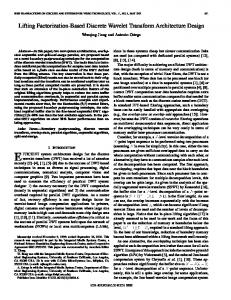
4.1 Data dependency diagram Fig. 2: Data dependency diagram for 4-stage lifting factorization of CDF 9/7 filters analysis, input
output
Every circle under the input stage represents an accumulator, arrows with a,b,c or d specify multipHcation with the respective constant. To explain the situation more in detail, we define a data dependency diagram, which focuses on data flow in the analyzing (synthesizing) structure (Fig.2). The data dependency diagram has an interestmg property - at any point of operation no extra
Personal Wireless Communications
493
memory is needed to store data dedicated for next step computation - making the whole transform possible to be done "in place". When compared with classic approach via convolution, for a 9-tap filter (worst case), not only we need to perform 9 multiplications and summarize them to generate one resluting sample, we also have to actually store 8 previous coefficients from the input stream for the next sample to be processed. Therefore, savings of the fast lifting approach are evident.
4.2 Boundary handling in general Because the filtering process is applied to finite signals, the coding system must handle boundaries with special approach to avoid discontinuity-based errors. A general solution to this problem is to extend the signal. Extending is done periodically at both boundaries. When using CDF 9/7 filterbank, we use the "whole-sample" symmetric extension (WSS), which is described in the following simple example [1]: Example: Consider a signal ABCDEFGH. For odd-length filters (which is a case of CDF 9/7) we can extend the signal (underlined) as HGFEDCBABCDEFGHGFEDCBA For even-length filters, a very simmilar way is proposed, known as HSS ("halfsample" symmetric extension), with the only difference being a duplication of the boundary item into the extended part, too (mirror symmetry). 4.3 Fast lifting boundary handling When we discuss the boundary handling of fast lifting approach [2], we usually adopt the point of view that treats every lifting step as a separate subband transform. That means, extension of the signal is defined due to the nature of the corresponding Laurent polynomial in (12). Because in the case of CDF 9/7 the degree of this polynomials is always 1 (odd-length filters), we use HSS extension with one sample. While observing the data dependency diagram on (Fig.2), we can deduce that no extra memory will be needed as we only have to estimate the value from the previous step symetrically to left or right, depending on the location of signal boundary (Fig.3). This leads to additional savings when compared to convolutional approach, where extra memory (or conditional algorithmic solution, which needs no extra memory, but on the contrary slows down the computation) is needed to extend the original signal and in the case of CDF 9/7 the extension is quite noticeable.
494
PWC 2007
Fig J : Data dependency diagram for fast lifting CDF 9/7 approach, with signal boundaries taken into consideration.
5 Java Implementation The proposed Java^^ implementation is based on two classes, one for convolutionalapproach dwt, which has been written for testing purposes, and one for lifting-based dwt. Both classes offer the same interface ~ with two static methods a n a l y z e () and s y n t h e s i z e ( ) , whose parameter is always the source data to be transformed to the resulting output. As we intend to use this lifting-based coder on tasks of lossy image compression in the ftiture, we must declare all the input and output memory space as double precision floating point numbers 1 „ Convolution-based coder is basically a periodically extended standard convolution of the source signal with the corresponding filter of the CDF 9/7 set. It uses extra memory buffer with extended source signal, as this solution is computationally most efficient. The only drawback is that we need to process the resulting array to gain only the relevant coefficients, which slows the process down. Lifting-based approach has no need to allocate extra memory space. It consists of four loops, that process the entire signal by the mean of each step's factorized filter. The signal is then scaled by the corresponding constant. As we use the "in-place" memory approach, source array is modified directly in the four steps. As visible fi-om data dependency diagram (Fig.2), odd values represent the high-pass output, while
It is indeed possible to use integers - for example in the case of lossless compression mode used by JPEG2000 format with LeGall 5,3 filterbank [2].
Personal Wireless Communications
495
even values stand for the low-pass output. Thus, we need to rearrange the resulting array to get whichever format suitable for our needs. Boundary handling is solved by the algorithm as proposed in the previous chapter, that means predicting values out of bounds by estimating it from 1-sample HSS extension. This solution is simple and results in perfect reconstruction (with the exception of precision-based floating point errors). Sample: A source code used to compute two adjacent lifting steps (predict and update) is listed here, x represents the full source data vector and n is length of the vector. a—1.586134342; for (i-l;i