Finite Model Reasoning on UML Class Diagrams via Constraint Programming Marco Cadoli1 , Diego Calvanese2 , Giuseppe De Giacomo1 , and Toni Mancini1 1
Dipartimento di Informatica e Sistemistica Universit`a di Roma “La Sapienza” Via Salaria 113, I-00198 Roma, Italy cadoli|degiacomo|
[email protected] 2 Faculty of Computer Science Free University of Bozen-Bolzano Piazza Domenicani 3, I-39100 Bolzano, Italy
[email protected]
Abstract. Finite model reasoning in UML class diagrams is an important task for assessing the quality of the analysis phase in the development of software applications in which it is assumed that the number of objects of the domain is finite. In this paper, we show how to encode finite model reasoning in UML class diagrams as a constraint satisfaction problem (CSP), exploiting techniques developed in description logics. In doing so we set up and solve an intermediate CSP problem to deal with the explosion of “class combinations” arising in the encoding. To solve the resulting CSP problems we rely on the use of off-the-shelf tools for constraint modeling and programming. As a result, we obtain, to the best of our knowledge, the first implemented system that performs finite model reasoning on UML class diagrams.
1
Introduction
The Unified Modelling Language (UML, [9], cf. www.uml.org) is probably the most used modelling language in the context of software development, and has been proven to be very effective for the analysis and design phases of the software life cycle. UML offers a number of diagrams for representing various aspects of the requirements for a software application. Probably the most important diagram is the class diagram, which represents all main structural aspects of an application. A typical class diagram shows: – classes, i.e., homogeneous collections of objects, i.e., instances; – associations, i.e., relations among classes; – ISA hierarchies among classes, i.e., relations establishing that each object of a class is also an object of another class; – multiplicity constraints on associations, i.e., restrictions on the number of links between objects related by an association. Actually, a UML class diagram represents also other aspects, e.g., the attributes and the operations of a class, the attributes of an association, and the specialization of an association. Such aspects, for the sake of simplicity, will not be considered in this paper.
Student
20..∗
1..1
Curriculum
enrolled
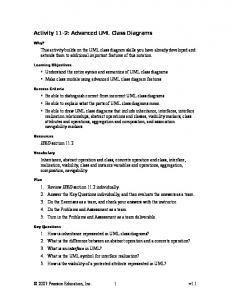
Fig. 1. A UML class diagram. 20..∗ Student
1..1 Curriculum
enrolled 1..1
likes
1..1
Fig. 2. A UML class diagram with finitely unsatisfiable classes.
An example of a class diagram is shown in Figure 1, which refers to an application concerning management of administrative data of a university, and exhibits two classes (Student and Curriculum) and an association (enrolled ) between them. The multiplicity constraints state that: – Each student must be enrolled in at least one and at most one curriculum; – Each curriculum must have at least twenty enrolled students, and there is no maximum on the number of enrolled students per curriculum. It is interesting to note that a class diagram induces restrictions on the number of objects. As an example, referring to the situation of Figure 1, it is possible to have zero, twenty, or more students, but it is impossible to have any number of students between one and nineteen. The reason is that if we had, e.g., five students, then we would need at least one curriculum, which in turn requires at least twenty students. In some cases the number of objects of a class is forced to be zero. As an example, if we add to the class diagram of Figure 1 a further association, likes, with the constraints that each student likes exactly one curriculum, and that each curriculum is liked by exactly one student (cf., Figure 2), then it is impossible to have any finite non-zero number of students and curricula. In fact, the new association and its multiplicity constraints force the students to be exactly as many as the curricula, which is impossible. Observe that, with a logical formalization of the UML class diagram, one can actually perform such a form of reasoning making use of automated reasoning tools3 . Referring to Figure 2, note that the multiplicity constraints do not rule out the possibility of having infinitely many students and curricula. When a class is forced to have either zero or infinitely many instances, it is said to be finitely unsatisfiable. For the sake of completeness, we mention that in some situations involving ISA hierarchies (not shown for brevity), classes may be forced to have zero objects, and are thus said to be unsatisfiable in the unrestricted sense. The above example shows that UML class diagrams do not have the finite model property, since unrestricted and finite satisfiability are different. Unsatisfiability, either finite or unrestricted, of a class is a symptom of a bug in the analysis phase, since either such a class is superfluous, or a conflict has arisen while 3
Actually, current CASE tools do not perform any kind of automated reasoning on UML class diagrams yet.
2
Syntax Semantics ¬B ∆I \ B I D1 u D2 D1I ∩ D2I D1 t D2 D1I ∪ D2I ∀R.D {a : ∀b. (a, b) ∈ RI → b ∈ DI }
Syntax Semantics (≥ m R) {a : |{b : (a, b) ∈ RI }| ≥ m} (≤ n R) {a : |{b : (a, b) ∈ RI }| ≤ n} P− {(a, b) : (b, a) ∈ P I }
Fig. 3. Syntax and semantics of ALUN I
modeling different, antithetic, requirements. In particular, finite unsatisfiability is especially relevant in the context of applications, e.g., databases, in which the number of instances is intrinsically finite. Global reasoning on the whole class diagram is needed to show finite unsatisfiability. For large, industrial class diagrams, finite unsatisfiability could easily arise, because different parts of the same diagram may be synthesized by different analysts, and is likely to be nearly impossible to be discovered by hand. In this paper, we address finite model reasoning on UML class diagrams, a task that, to the best of our knowledge, has not been attempted so far. This is done by exploiting an encoding of UML class diagrams in terms of Description Logics (DLs) [2], in order to take advantage of the finite model reasoning techniques developed for DLs [4, 5].These techniques, which are optimal from the computational complexity point of view, are based on a reduction of reasoning on a DL knowledge base to satisfaction of linear constraints. The contribution of this paper is on the practical realization of such finite modeling reasoning techniques by making use of off-the-shelf tools for constraint modelling and programming. In particular, by exploiting the finite model reasoning technique for DLs presented in [4, 5], we propose an encoding of UML class diagram satisfiability as a Constraint Satisfaction Problem (CSP). We show that, in spite of the high computational complexity of the reasoning task in general, the aforementioned techniques are feasible in practice, if some optimizations are performed in order to reduce the exponential number of variables in the constraint problem. We do so by relying again on the constraint solver itself, by setting up and solving an auxiliary constraint problem that exploits the structure of real-world UML class diagrams. We built a system that accepts as input an UML class diagram (written in the standard MOF syntax4 ), and reasons on it according to the ideas above making use of the ILOG’s OPLSTUDIO constraint system. The system allowed us to test the technique on the industrial knowledge base CIM.
2
Description Logics
DLs [1] are logics for representing a domain of interest in terms of classes and relationships among classes and reasoning on it. They are extensively used to formalize conceptual models and object-oriented models in databases and software engineering [3, 2], and lay the foundations for ontology languages used in the Semantic Web [7]. 4
http://www.dmtf.org/
3
In DLs, the domain of interest is modeled through concepts, denoting classes of objects, and roles, denoting binary relations between objects. The semantics of DLs is given in terms of an interpretation I = (∆I , ·I ) consisting of an interpretation domain ∆I and an interpretation function ·I that maps every concept D to a subset DI of ∆I and every role R to a subset RI of ∆I × ∆I . In this paper we deal with the DL ALUN I [4, 5], whose syntax and semantics are shown in Figure 3 (B and P denote respectively atomic concepts and roles, D and R respectively arbitrary concepts and roles, m a positive integer, and n a non-negative integer). The constructs (≥ m R) and (≤ n R) are called number restrictions. We refer to [1] for more details on DLs. An ALUN I knowledge base (KB) is constituted by a finite set of (primitive) inclusion assertions of the form B v D. An interpretation I is called a model of a KB if B I ⊆ DI for each assertion B v D in the KB. The basic reasoning tasks in DLs are (finite) KB and concept satisfiability: a KB is (finitely) satisfiable if it admits a (finite) model; a concept C is (finitely) satisfiable in a KB, if the KB admits a (finite) model I such that C I 6= ∅. Due to the expressiveness of the constructs present in ALUN I KBs, unrestricted and finite satisfiability are different problems, i.e., ALUN I does not have the finite model property (cf. [5]). Unrestricted model reasoning is a quite well investigated problem in DLs, and several DL reasoning systems that perform such kind of reasoning are available (e..g, FACT ++5 or R ACER6 ). Instead, finite model reasoning is less well studied, both from the theoretical and from the practical point of view. To the best of our knowledge, no implementation of finite model reasoners has been attempted till now. Some works provide theoretical results showing that finite model reasoning over a KB can be done in EXPTIME for variants of expressive DLs, including ALUN I [4, 5, 11]. Notice that this bound is tight, since (finite) model reasoning is already EXPTIME-hard even for much less expressive DLs (enjoying the finite model property) [1]. These results are based on an encoding of the finite model reasoning problem into the problem of finding particular integer solutions to a system of linear inequalities. Such solutions can be put in a direct correspondence with models of the KB in which the values provided by the solution correspond to the cardinalities of the extensions of concepts and roles. Also, the specific form of the system of inequalities guarantees that the existence of an arbitrary solution implies the existence of an integer solution. Moreover, from the encoding it is possible to deduce the existence of a bound on the size of an integer solution, as specified by the following theorem. Theorem 1 ([5]). Let K be an ALUN I KB of size K, C an atomic concept, ΨK,C the system of linear inequalities derived from K and C, and N the maximum number appearing in number restrictions in K. Then, C is satisfiable in K if and only if Ψ K, B admits a solution. Moreover, if a solution exists, then there is one whose values are bounded by (K · N )O(K) . In the following, we will exploit the above result to derive a technique for reasoning on UML class diagrams that properly takes into account finiteness of the domain of 5 6
http://owl.man.ac.uk/factplusplus/ http://www.racer-systems.com/
4
C C1
m2 ..n2
m1 ..n1
C2
A C1
C2
(a)
...
Cn
(b)
Fig. 4. (a) UML binary association with multiplicity constraints. (b) ISA hierarchy.
interest. The technique is a based on an encoding of UML class diagrams in terms of DL KBs, which we present in the next section.
3
Formalizing UML Class Diagrams in DLs
UML class diagrams allow for modelling, in a declarative way, the static structure of an application domain, in terms of concepts and relations between them. We briefly describe the core part of UML class diagrams, and specify the semantics of its constructs in terms of ALUN I [2]. A class in a UML class diagram denotes a set of objects with common features. Formally, a class C corresponds to a concept C. Classes may have attributes and operations, but for simplicity we do not consider them here, since they don’t play any role in the finite class unsatisfiability problem. A (binary) association in UML is a relation between the instances of two classes. An association A between two classes C1 and C2 is graphically rendered as in Figure 4(a). The multiplicity m1 ..n1 on the binary association specifies that each instance of the class C1 can participate at least m1 times and at most n1 times to A, similarly for C2 . ∗ is used to specify no upper bound. 7 An association A between the instances of classes C1 and C2 , can be formalized as an atomic role A characterized by: C2 v ∀A− .C1
C1 v ∀A.C2
For an association as depicted in Figure 4(a), multiplicities are formalized by: C2 v (≥ m2 A− ) u (≤ n2 A− )
C1 v (≥ m1 A) u (≤ n1 A)
In UML, one can use a generalization between a parent class and a child class to specify that each instance of the child class is also an instance of the parent class. Hence, the instances of the child class inherit the properties of the parent class, but typically they satisfy additional properties that in general do not hold for the parent class. Several generalizations can be grouped together to form a class hierarchy (also called ISA hierarchy), as shown in Figure 4(b). Disjointness and completeness constraints can also 7
In UML, an association can have arbitrary arity and relate several classes, but for simplicity we do not consider this case here (but see Conclusions). Aggregations, which are a particular kind of binary associations are modeled similarly to associations.
5
be enforced on a class hierarchy (graphically, by adding suitable labels). A class hierarchy is said to be disjoint if no instance can belong to more than one derived class, and complete if any instance of the base class belongs also to some of the derived classes. A class C generalizing a class C1 can be formalized as: C1 v C. A class hierarchy as shown in Figure 4(b) is captured by Ci v C, for i = 1, . . . , n. Disjointness among C1 , . . . , Cn is expressed by: Ci v
Vn
j=i+1
¬Cj ,
for i = 1, . . . , n − 1
The completeness constraint expressing that each instance of C is an instance of at least one of C1 , . . . , Cn is expressed by: C v
Fn
i=1
Ci
Here, we follow a typical assumption in UML class diagrams, namely that all classes not in the same hierarchy are a priori disjoint. Another typical assumption, called unique most specific class assumption, is that objects in a hierarchy must belong to a single most specific class. Hence, under such an assumption, two classes in a hierarchy may have common instances only if they have a common subclass. We discuss in the next section the effect of making the unique most specific class assumption when reasoning on an UML class diagram. The basic form of reasoning on UML class diagrams is (finite) satisfiability of a class C, which amounts to checking whether the class diagram admits a (finite) instantiation in which C has a nonempty extension. Formally, this corresponds to checking whether the concept corresponding to C is (finitely) satisfiable in the KB formalizing the diagram, Notice that, as mentioned, unrestricted and finite satisfiability in UML class diagrams (and also in ALUN I) are different problems. The formalization of UML class diagrams in terms of DLs [2], and the fact that instantiations of the UML class diagram must be finite, allows one to use on such diagrams the techniques for finite model reasoning in DLs discussed in Section 2. Specifically, the EXPTIME upper bounds apply also to finite model reasoning on UML class diagrams [2]. Instead, the exact lower bound of reasoning on UML class diagrams as presented above is still open. However, if one adds subsetting relations between associations or the ability of specializing the typing of an association for classes in a generalization, then both unrestricted and finite model reasoning are EXPTIME-hard (see [2]). This justifies the approach taken in the next section, where we address the problem of finite model reasoning on UML class diagrams also from a practical point of view.
4
Finite Model Reasoning on UML Class Diagrams via CSP
We address now finite class satisfiability in UML class diagrams, and show how it is possible to encode the problem as a constraint satisfaction problem (CSP). As mentioned, a technique for finite model reasoning in UML class diagrams can be derived from techniques developed in the context of DLs. Such techniques are based 6
on translating a DL knowledge base into a set of linear inequalities [4, 5]. The formalization of UML class diagrams in terms of DLs implies that the finite model reasoning techniques for DLs can be used also for UML class diagrams. In the rest of this paper, we will deal directly with the UML class diagram constructs, considered, from a formal point of view, as abbreviations for the corresponding DL concepts and roles. Intuitively, consider a simple UML class diagram D with no generalizations and hierarchies. Figure 4(a) shows a fragment of such a diagram, in which we have two classes C1 and C2 and an association A between them. It is easy to see that such a class diagram D is always satisfiable (assuming mi ≤ ni ) if we admit infinite models. Hence, only finite model reasoning is of interest. We observe that, if D is finitely satisfiable, then it admits a finite model in which all classes are pairwise disjoint. Exploiting this property, we can encode finite satisfiability of class C1 in D in a constraint satisfaction problem. The variables and the constraints of the CSP are modularly described considering in turn each association of the class diagram. Let A be an association between classes C1 and C2 such that the following multiplicity constraints are stated (cf. Figure 4(a)): – There are at least m1 and at most n1 links of type A (instances of the association A) for each object of the class C1 ; – There are at least m2 and at most n2 links of type A for each object of the class C2 . In the special case in which neither C1 nor C2 participates in an ISA hierarchy, the CSP is defined as follows: – There are three non-negative variables c1, c2, and a, which stand for the number of objects of the classes and the number of links8 , respectively (upper bounds for these variables follow from Theorem 1; in practice, they can be set to a huge constant, e.g., maxint); – There are the following constraints (we use, here and in what follows, a syntax similar to that of OPL[12]): 1. 2. 3.
4. 5. 6.
m1 * c1 = a; m2 * c2 = a; a = 1;
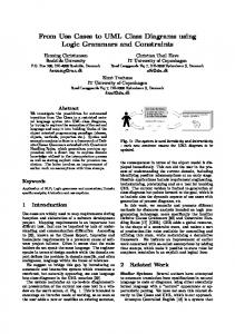
Constraints 1–4 account for the multiplicity of the association; they can be omitted if either m1 or m2 is 0, or n1 or n2 is ∞ (symbol ‘*’ in the class diagram). Constraint 5 sets an upper bound for the number of links of type A with respect to the number of objects. Constraint 6 encodes satisfiability of class C1 : we want at least one object in its extension. As an example, consider the Restaurant class diagram, shown in Figure 5: if A stands for served in, C1 stands for menu, and C2 stands for banquet, then m1 is 1, n1 is ∞, m2 is 1, and n2 is 1. Finally, to avoid the system returning an ineffectively large solution, an objective function that, e.g., minimizes the overall number of objects and links, may be added. 8
The use of variables standing for the number of links stems from the technique proposed in [5], which ensures soundness and completeness of reasoning. It remains to be investigated whether a simpler encoding avoiding the use of such variables is possible.
7
Fig. 5. The Restaurant UML class diagram.
It is possible to show that, from a solution of such a constraint system we can construct a finite model of the class diagram in which the cardinality of the extension of each class and association is equal to the value assigned to the corresponding variable9 [10]. When either C1 or C2 are involved in ISA hierarchies, the constraints are actually more complicated, because the meaning of the multiplicity constraints changes. As an example, the multiplicity 1..* of the order association in Figure 5 states that a client orders at least one banquet, but the client can be a person, a firm, both, or neither (assuming the generalization is neither disjoint nor complete). In general, for an ISA hierarchy involving n classes, 2n non-negative variables corresponding to all possible combinations must be considered. For the same reason, in our example, we must consider four distinct specializations of the order association, i.e., one for each possible combination. Summing up, we have the following non-negative variables: – – – –
person, order p, for clients who are persons and not firms; firm, order f, for clients who are firms and not persons; person firm, order pf, for clients who are both firms and persons; client, order c, for clients who are neither firms nor persons;
plus the non-negative banquet variable. The constraints which account for the order association are as follows: 9
In fact, if one is interested just in the existence of a finite model, the nonlinear constraints a ≤ c1 ∗ c2 can be dropped. Indeed, any solution of the resulting constraint system can be transformed into one that satisfies also the nonlinear constraint by multiplying it with a sufficiently large constant, cf. [5].
8
/* 1 /* 2 /* 3 /* 4 /* 5 /* 6 /* 7 /* 8 /* 9 /* 10
*/ */ */ */ */ */ */ */ */ */
client