Fuzzy based Sliding Mode Control for Vector Controlled Induction Motor Shoeb Hussain Dept. of Electrical Engineering NIT, Srinagar J&KINDIA
[email protected]
Mohammad Abid Bazaz Dept. of Electrical Engineering NIT, Srinagar J&KINDIA
[email protected]
Abstract-A vector controlled induction motor drive with fuzzy based sliding mode controller (SMC) is presented in this paper for improving the dynamic performance of the drive. The
followed by the proposed fuzzy based SMC in section IV. The simulation results are presented in section V followed by conclusions in section VI.
fuzzy based SMC employed for speed control compensates for the chattering effect otherwise present with SMC. MATLAB
simulation of the scheme for a 5HP, 460 V (50Hz) induction motor is presented to analyse the performance of fuzzy based SMC.
Keywords-Sliding control;
mode
I.
controller;
Fuzzy
logic;
Vector
INTRODUCTION
Vector control of induction motor has resulted in the development of high performance drive systems. With vector control, it is possible to control the flux and torque of a three phase induction motor independently and in a similar fashion to that of a separately excited DC motor. The control of flux and torque has been proposed in literature by the development of different methods [1]. Speed/torque control has been achieved through implementation of different controllers such as PI, fuzzy and neural networks. Sliding mode controller (SMC) has also been implemented for speed control in vector controlled drives [2].
II.
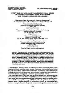
In order to understand the vector control of induction motor, first the development of a dynamic model of the induction motor is necessary. It involves transformation of the three phase stator currents into two orthogonal DC vectors id (direct current component) and iq (quadrature current component), derived from Park's transformation, in a rotor reference frame. The dynamic model of the induction motor is shown in Fig. 1. Iq,-
This paper is divided into 6 sections. Following the Introduction, vector control of induction motor is presented in section II. In section III, Sliding mode controller is described
978-1-4799-3080-7114/$31.00 ©20l4
IEEE
"'-iqr
Vq'
ids�
Sliding mode controller is highly effective and robust in nature for controlling the speed of induction motor drive system. The feedback, particularly with high gain is effective for the nonlinearities, parameter variations and disturbances in the system [3]. The dynamic performance and stability of the system is improved. However the main drawback of the SMC is 'chattering'. The chattering is because of the discontinuous control action of the SMC. Due to chattering, high torque pulsations are introduced in the system. This paper presents a fuzzy based sliding mode control for speed control of the drive. The use of fuzzy and neural with SMC has been presented in [4-6]. However, in this paper, fuzzy controller is used in feedback with SMC for speed control of the drive. In this method, the SMC is responsible for speed control and the fuzzy controller reduces the associated chattering problem.
VECTOR CONTROL OF INDUCTION MOTOR
-
idr
'0rRr
Vd,
1
Vdr
Fig. I Equivalent dynamic model of lnduction motor a) quadrature-axis circuit b) direct-axis circuit
The purpose of vector control is to control the induction motor drive in a similar fashion to that of a separately excited DC motor [1]. The independent control of torque and flux quantities can be exhibited in case of an induction motor through decoupling, possible only when the three line currents (ia' h, ic) are transformed to two orthogonal DC quantities (id and iq). Vector control allows the control of phase in addition to magnitude and frequency. The flux is independently controlled through direct current component id and the torque
811
is controlled by controlling the quadrature current component iq.
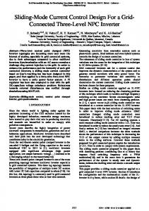
and (5) respectively. In this scheme, Hysteresis current controller is used to compare the reference stator current and
The Park's transformation equation necessary for decoupling in case of three phase induction motor is given as
27r
2
Id =TI b =qO ac 3
3-ph 50Hz Ac supply
•••
27r
cosB cos(B--) -sinB -sin(B--) -:i�;:+ i;! [�:l(1) 3
27r 3
2
Ie
1
2
2
VS[
The inverse transform is: Current
2
I b = TId 0 = ac q 3
Sensor
B
cosB -sin cos(B--) -sin(B--) cos(B + -) -sin(B + -) 27r
27r
3
3
27r
27r
3
3
Fig. 2 Block diagram of indirect vector controlled induction motor
In the vector controlled induction motor drive, the expression of rotor flux is given as (3) In the dq reference frame, the electromagnetic torque is given by (4) The d-q frame rotates along with the rotor flux (which is maintained at its rated value). The d-axis is aligned with the direction of the rotor flux which makes the q-axis component of rotor flux null and the expression of the electromagnetic torque simplifies as follows Te
=
(3 (2
x x
P
x
Lm)
2
x
Lr )
x
(If
dr
(5)
i qs )
(6) where,
The mechanical equation of the induction motor drive is represented as: (7) where, 'J' is the moment of inertia, l' is the damping coefficient and 'TL' is the external load. Substituting (6) in (7)
() t
=
-
f J
-
t ' ()
OJ.
+
K, .
The SMC is basically an adaptive controller designed for variable control structures [1]. The use of SMC is possible for both linear and non-linear systems. The controller results in robust performance of the drive for parameter variation and load changes. The SMC forces the system to track or slide along a reference trajectory defined in phase plane by the use of switching algorithm. The SMC can be applied to induction motor drive so as to draw high performance from the motor irrespective of parameter variations, including variations in moment of inertia 'J', damping coefficient l' and load torque 'TL '. The control system is dependent on the sliding surface. The response of the system is forced along the reference trajectory [7].
J
-
eel) where speed.
(Or
*
and
(Or
=
l1J; -l1Jr
(9)
are the reference and measured rotor
Taking derivative of (9), we have
e(t)
=
OJ,.
- OJ ,.
(lO)
The sliding surface is defined as:
1 [ -- T q
J
L
(8)
The schematics of the vector controlled drive are shown in Fig. 2. The controlled values of id and iq are obtained from (3)
812
SLIDING MODE CONTROL
as
=
OJ,.
III.
For a vector controlled induction motor, error is calculated
'f/dr 'f/r
.
the controlled current in order to generate the PWM pulses as the gating signal for the inverter.
S
=
.-1 ( e(t)) + e(t)
(11)
where, A is a constant dependent on the slope of the sliding line. The controller enforces the error and its derivative to
2014 International Conference on Advances in Computing, Communications and Informatics (ICACCI)
remain at zero along the trajectory, through a switching process which changes the controller action back and forth between the positive and negative controller gain. The control output of the SMC is given as (12) u\
=
Ksgn(S)
(13)
where, 'K' is controller gain. 'K' must be posItIVe constant. The mathematic form of this condition satisfies the Lyapunov stability criteria: .
sxs