Advances in Powertrains and Automotives, 2015, Vol. 1, No. 1, 34-41 Available online at http://pubs.sciepub.com/apa/1/1/4 © Science and Education Publishing DOI:10.12691/apa-1-1-4
Fuzzy Self Tuning of PID Controller for Active Suspension System A S. Emam* Department of Automotive and Tractors Engineering, Faculty of Engineering, Mataria, Helwan University, Cairo, Egypt *Corresponding author:
[email protected]
Received June 26, 2015; Revised July 07, 2015; Accepted July 09, 2015
Abstract Suspension system plays an imperative role in retaining the continuous road wheel contact for better road holding. In this paper, fuzzy self-tuning of PID controller is designed to control of active suspension system for quarter car model. A fuzzy self-tuning is used to develop the optimal control gain for PID controller (proportional, integral, and derivative gains) to minimize suspension working space of the sprung mass and its change rate to achieve the best comfort of the driver. The results of active suspension system with fuzzy self-tuning PID controller are presented graphically and comparisons with the PID and passive system. It is found that, the effectiveness of using fuzzy self-tuning appears in the ability to tune the gain parameters of PID controller
Keywords: activesuspension system, PID controller, fuzzy logic control, self-tuning controller Cite This Article: A S. Emam, “Fuzzy Self Tuning of PID Controller for Active Suspension System.” Advances in Powertrains and Automotives, vol. 1, no. 1 (2015): 34-41. doi: 10.12691/apa-1-1-4.
1. Introduction Ride comfort and vehicle handling have become two of the important criteria in a passenger vehicle which is directly related to driver fatigue, discomfort, and safety. The purpose of the suspension systems are attempted to isolate vehicle vibration excitations from being transmitted to the drivers and to improve passenger comfort [1,2]. Conventional suspension system has fix criteria of spring and damping. These two mechanical components have some limitation in isolating vibration especially in various types of road profiles [3]. Also, in order to improvement the passenger comfort, the passive elements (springs and dampers) must be selected in soft part, but in order to increase the qualification of driving the passive elements must be selected in harder part. This discrepancy in selection the type of passive elements indicates that, we cannot attain to both two objectives by using the passive suspension system [4,5]. Therefore, the suspension system needs to change the system specifications in a dynamic aspect according to the conditions of the road. So, several semi-active, active, and fully active suspension approach have been designed and built to address this problem. Nowadays, many researchers give more attention in proposed and implemented various semi-active and active vehicle suspension systems both theoretically as well experimentally into real-time application. Hac [6] derived the preview control problem of an active vehicle suspension with a quarter-car model and showed that the suspension performance could be improved by using preview information. Gordon [7] proposed the optimal control of a semi-active vehicle suspension system for quarter-vehicle model. Analysis is based on a simple fifth-
order mathematical model of the ride dynamics of an automotive suspension. The semi-active control of vehicle suspension system with magnetorheological damper was presented by Yao et al. [8]. Bouazara and Richard [9] analyzed the effects of vibrations on comfort and road holding capability of road vehicles as observed in the variation of different parameters such as suspension coefficients, road disturbances and the seat position. Du et al. [10] studied the application of MR dampers to semiactive of vehicle suspension. A multi-objective genetic algorithm for assessing the optimality of control algorithms for semi-active vehicle was developed by Crews et al. [11]. The evaluation of experimental performance for an LQ-based semi-active and controller concept was investigated by Unger et al. [12]. Li et al. [13] proposed a multi-objective control method for active vehicle suspension of four-degree-of-freedom half-car model. Recently, various control strategies have been proposed to control the activeand active suspension system. Linear Quadratic Gaussian (LQG) control, adaptive control, robust control, and non-linear control are developed and proposed to manage the occurring problems [14,15,16]. Multi-objective functional such as H2, H∞, GL2, GH2, GA, etc. control of vehicle suspensions attracts more attention many researchers [17,18,19,20]. Fuzzy logic control (FLC) and PID controller approach has been fruitful research area with semi-active and active suspension system [21,22,23,24]. The main objective of this paper, we present a multiobjective control for the active suspension system for quarter car model by using PID controller. Previous methods are used to determine the gains of PID do not guarantee the best performance of the system, which support the important of fuzzy self-tuning method to
Advances in Powertrains and Automotives
obtain the parameters of PID for the best Performance. A fuzzy self-tuning is used to develop the optimal control parameters for PID controller to minimize suspension working space of the sprung mass and its change rate to achieve the best comfort of the driver.
35
The proposed active suspension system can be represented in the state space notation:
x =Ax + BFa + Dxr Where, the matrices A ∈ R (4×4) , B ∈ R (4×1) , and
D ∈ R (4×1) as:
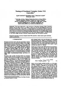
2. Mathematical Model Formulation 2.1. Active Suspension System This section is devoted to the mathematical modeling of proposed model. Figure 1 shows the two-degrees-offreedom system that represents the quarter-vehicle active suspension model. It consists of an upper mass M s , representing the body mass (sprung mass), as well as a lower mass M u , representing the wheel mass (un-sprung mass), and its associated parts. The vertical motion of the system is described by the displacements xs , and xu , while the excitation due to road disturbance is xr . The suspension spring constant is k s , damping coefficient is
bs , and the tyre spring constant is kt (the tyre damping is neglected) . The data employed here for the quartervehicle system are listed in Table 1 [25].
0 0 (k + k ) A = − s t Mu ks M s
0 0
1 0
ks Mu
b − s Mu
k − s Ms
bs Ms
0 0 1 − B = = and , D Mu 1 Ms
0 1 bs , Mu b − s M s
0 0 kt Mu 0
The output equation y can be calculated by using the matrices C ∈ R (4×1) to: y = Cz
1 0 0 0 Where, C = . 0 −1 0 0 For the active suspension, the actuator force Fa depends on the time histories of the relative displacement x across it: = x xs − xu Where, x is also referred to as the suspension working space (SWS). In this paper, it is assumed that only the suspension working space could be measured and used by the controllers.
2.2. Road Excitation Profile Figure 1. Quarter-vehicle suspension model
Road profile is considered by single bump, chosen to be very similar to the real-world road profiles. The road bump was described in reference [27] as:
Table 1. Quarter vehicle suspension parameters [25] Parameter Mass of vehicle body Mass of vehicle wheel Suspension stiffness Damping coefficient Tyre stiffness
Symbol 𝑀𝑀𝑠𝑠 𝑀𝑀𝑢𝑢 𝑘𝑘𝑠𝑠 𝑏𝑏𝑠𝑠 𝑘𝑘𝑡𝑡
Value (Unit) 240 (kg) 36 (kg) 16 (kN/m) 980 (Ns/m) 160 (kN/m)
d a{1 − cos cos ωr ( t − 0.5 ) )}, for 0.5 ≤ t ≤ 0.5 + xr = V 0, otherwise
By applying Newton’s second law the equations of motion for the sprung and unsprung masses of the quartercar suspension model are given by [26]:
M s xs + k s ( xs − xu ) + Fa = 0
(1)
M u xu + k s ( xs − xu ) + kt ( xu − xr ) − Fa = 0
(2)
Fa : is the control force from the hydraulic actuator. The equations of motion can be summarized by using the following notation: x = [ xs
xu
xs
xu ]
T
2πV , d is d the width of bump, and V is the vehicle velocity. In this study, a=0.035 m, d=0.8m, and V= 0.856 m/s, as in reference [28]. Where, a is the half the bump amplitude, ωr =
3. Fuzzy Self Tuning of PID Design Procedure Tuning of a PID controller is to tune or choose numerical values for the PID coefficients are proportional
36
Advances in Powertrains and Automotives
(Kp), integral (Ki) and derivative (Kd) to achieve an optimized value of the desired response. The proposed design procedure includes two steps: 1. Find the optimal gains of PID which are controlled the system. 2. Design Fuzzy logic control (FLC) part, which has self tuning capabilities for the obtained PID.
3.1. Optimal PID Controller Ziegler and Nichols method to tune the coefficients of a PID controller became the focus of research and become better understood, but cannot guarantee to be always
effective. For this reason, this paper investigates the design of self tuning for a PID controller. The transfers function of the PID controller given as [29]:
k k ( s ) = k p + i + kd s s
(3)
Where, K P is proportional gain, Ki is the integral gain, K d is the derivative gain. Figure 2 shows the block diagram of PID controller, and Figure 3 illustrates the matlab/simulink model of active suspension system with PID controller.
Figure 2. Block diagram of PID controller
Figure 3. Simulink of active suspension system with PID controller
The proportional, integral and derivative terms are summed to calculate the output of the PID controller. The final output defined by u(t) and it given by [29]:
t
u (t ) = K P e ( t ) + Ki ∫e ( x ) dx + K d 0
de(t ) dt
Advances in Powertrains and Automotives
Where, e is the error present in the controller, t is the time or instantaneous time, and x is the variable of integration, taken from zero to present one.
3.2. Designs Steps of Fuzzy Self Tuning for the PID Controller In this section the Fuzzy Self Tuning for the PID Controller is designed. The PID fuzzy controller can be decomposed into the equivalent proportional control, integral control and the derivative control components. The designs steps of fuzzy self tuning can be summarized as follows [30]: Write the PID controller by the following equation:
U= K P + K I ∫edt + K D
de(t ) dt
This equation can be written as:
U= K P 2 + K I 2 ∫edt + K D 2
de ( t ) dt
Where, = K P 2 K= P *K P1 , K I 2 K= I *K I 1 , K D 2 K D *K D1 , and Kp1, KI1 , KD1 are the gain outputs from fuzzy controller. • Put the input membership functions of e and ∆e as linguistic labels. The inputs are {Negative Big, , Negative medium, Negative small, Zero, Positive small, Positive medium, Positive Big}, and are referred to in the rules bases as {NB,NM,NS,ZE,PS,PM,PB}, and the linguistic labels of the outputs are {Negative Big, Negative medium, Negative small, Zero, Positive small, Positive medium, Positive Big} and referred to in the rules bases as {NB,NM,NS,ZE,PS,PM,PB }. There are 49 rules in the rule base used as presented in Table 2. • Calculate the values of normalizing gain by dividing the boundary values of the universe of discourse of the input member ship functions of e and ∆e and by the maximum of the original values of e and ∆e ,
37
respectively. This is to normalize them within the boundaries of the membership universe of discourse. • Apply the defuzzification process as final step to converts the fuzzy output to crisp value to be used as a non-fuzzy control action. • Choose the most popular defuzzification method that is the center of gravity or center of area which is formulated as follows:
∑ u (ui )ui u = i =1 r ∑ i =1u (ui ) r
where u(ui) is the membership grad (weight) of the element ui which is the output of the rule. This paper proposed two inputs-three outputs self tuning of a PID controller. The controller design used the error and rate of error as inputs to the fuzzy self tuning, and the gains as outputs. The FLC is adding to the PID controller to adjust the parameters of the PID controller on-line according to the change of the signals error and change of the error. The controller proposed also contain scaling gains inputs as shown in Figure 4. Figure 5 illustrates the matlab/simulink model of active suspension system with fuzzy self tuning controller. Figure 6 shows the input and output relations in the form of Cartesian rule surfaces.
Figure 4. Block diagram of fuzzy pid controller
Figure 5. Simulink of active suspension system with fuzzy self tuning PID controller
38
Advances in Powertrains and Automotives Table 2. Rules table for fuzzy inference system NB
NM
NS
ZE
PS
PM
PB
NB
NB
NB
NB
NB
NM
NS
ZE
NM
NB
NB
NB
NM
NS
ZE
PS
NS
NB
NB
NM
NS
ZE
PS
PM
ZE
NB
NM
NS
ZE
PS
PM
PB
PS
NM
NS
ZE
PS
PM
PB
PB
PM
NS
ZE
PS
PM
PB
PB
PB
PB
ZE
PS
PM
PB
PB
PB
PB
4. Results and Discussion Figure 7-Figure 10 present the selected results of active suspension system for self tuning fuzzy PID comparison
with the normal PID and passive suspension model. Figure 7 shows, the suspension working space for self tuning fuzzy PID controller with various times. The obtained results were compared with passive model and normal PID controller. It is clear that, the active suspension system with self tuning fuzzy PID gives lower value of suspension working space. Also, the suspension working space for self tuning fuzzy PID controller reaches steady state faster than normal PID controller, which faster than passive suspension. Figure 8 presents, the body acceleration for self tuning fuzzy PID controller compared with passive and normal PID controller. It is observed that, the active suspension system with self tuning fuzzy PID gives lower value of vertical peak as compared with passive suspension and normal PID controller. This result indicated to improve the driver comfort and better potential.
Figure 6. Input and output relations in the form of Cartesian rule surfaces for P, I, and D parameters. (a) P parameter; (b) I parameter; (c) D parameter
Figure 7. Suspension working space (SWS) for self tuning fuzzy PID controller compared with passive and normal PID controller
Advances in Powertrains and Automotives
39
Figure 8. Vehicle body acceleration (𝑧𝑧̈𝑏𝑏 ) for self tuning fuzzy PID controller compared with passive and normal PID controller
Figure 9 shows, the dynamic tyre load for self tuning fuzzy PID controller compared with passive and normal PID controller. It is clear that, the active suspension system with self tuning fuzzy PID gives lower value of
dynamic tyre load as compared with passive suspension and normal PID controller. This result indicated the self tuning fuzzy PID controller has lower values of maximum over shoots, which is directly related to driver safety.
Figure 9. Dynamic tyre load (DTL) for self tuning fuzzy PID controller compared with passive and normal PID controller
Figure 10 presents, the wheel displacement of self tuning fuzzy PID controller compared with passive and normal PID controller. The obtained result indicates that, the active suspension system with self tuning fuzzy PID
gives lower values of maximum over shoots and lower. Also, It is clear that wheel displacement with self tuning fuzzy PID controller reaches steady state faster than normal PID controller.
Figure 10. Wheel displacement for self tuning fuzzy PID controller compared with passive and normal PID controller
40
Advances in Powertrains and Automotives
Figure 11. The generated control force of fuzzy self tuning controller
Figure 11 shows the generated control force for fuzzy self tuning controller. The results obtained by self tuning fuzzy PID controller were compared to those passive and normal PID controller in terms of Roots Mean Square
(RMS) values are illustrates in Table 3. It can be observe that, the fuzzy self tuning pid controller gives better results as compared to pid controller and passive suspension.
Table 3. QUARTER VEHICLE RIDE COMFORT PARAMETERS Suspension Working Space (m) Body Acceleration (m/s2) Dynamic Tyre Load(N) 0.010680 0.9162 249 0.008829 0.7895 192 0.006130 0.6962 156.9 30.6 % 11.8 % 18.3 % World Congress on Engineering, 2010, vol. II, June 30 - July 2, 2010, London, U.K. [3] R. ROSLI, M. MAILAH, and G. PRIYANDOKO, “Active Suspension System for Passenger Vehicle using Active Force Control with Iterative Learning Algorithm,” WSEAS Trans. Syst. In this paper, a fuzzy self-tuning is designed to develop CONTROL, vol. 9, pp. 120-129., 2014. [4] W. Abbas, A. Emam, S. Badran, M. Shebl, and O. Abouelatta, the optimal control gain for PID controller for a quarter “Optimal Seat and Suspension Design for a Half-Car with Driver car model of a passenger car to improve the ride comfort Model Using Genetic Algorithm,” Intell. Control Autom., vol. 4, and road holding ability. The following points have been pp. 199, 2013. concluded: [5] H. Hashemipour, “Nonlinear Optimal Control of Vehicle Active Suspension Considering Actuator Dynamics.” International • The results and plot indicate that self tuning fuzzy Journal of Machine Learning and Computing, vol. 2, pp. 355-359, PID controller are less oscillatory, and have lower 2014. values of maximum over shoots, compared with [6] A. HAĆ, “Optimal linear preview control of active vehicle passive and normal PID controller. This is directly suspension,” Veh. Syst. Dyn., vol. 21, pp. 167-195, 1992. related to improve driver fatigue, discomfort, and [7] T. J. Gordon, “Non-linear optimal control of a semi-active vehicle suspension system,” Chaos Solitons Fractals, vol. 5, pp. 1603safety. 1617, 1995. • It is found that, self tuning fuzzy PID controller [8] G. Z. Yao, F. F. Yap, G. Chen, Wh. Li, and S. H. Yeo, “MR reaches steady state faster than normal PID controller, damper and its application for semi-active control of vehicle which faster than passive suspension for all the suspension system,” Mechatronics, vol. 12, pp. 963-973, 2002. dynamic performance. [9] M. Bouazara and M. J. Richard, “An optimal design method to control the vibrations of suspensions for passenger cars,” in • Also, it can be observed that, the value of suspension International Mechanical Engineering Congress and Exposition: working space has been reduced by sprung mass The Winter Annual Meeting of ASME, Atlanta, DSC, 1996, vol. 58, displacement has been reduced by 30.6 % which pp. 61-68. shows the improvement in ride comfort, sprung mass [10] H. Du, K. Yim Sze, and J. Lam, “Semi-active H∞ control of vehicle suspension with magneto-rheological dampers,” J. Sound acceleration reduced by 11.8 % and dynamic tire Vib., vol. 283, pp. 981-996, 2005. load reduced by 18.3 %. [11] J. H. Crews, M. G. Mattson, and G. D. Buckner, “Multi-objective control optimization for semi-active vehicle suspensions,” J. Sound Vib., vol. 330, pp. 5502-5516, 2011. [12] A. Unger, F. Schimmack, B. Lohmann, and R. Schwarz, “Application of LQ-based semi-active suspension control in a vehicle,” Control Eng. Pract., vol. 21, pp. 1841-1850, 2013. [1] W. Abbas, O. B. Abouelatta, M. El-Azab, M. Elsaidy, A. A. [13] P. Li, J. Lam, and K. C. Cheung, “Multi-objective control for Megahed, and others, “Optimization of biodynamic seated human active vehicle suspension with wheelbase preview,” J. Sound Vib., models using genetic algorithms,” Engineering, vol. 2, pp. 710vol. 333, pp. 5269-5282, 2014. 719, 2010. [14] T. E. Duncan, L. Guo, and B. Pasik-Duncan, “Adaptive [2] W. Abbas, O. B. Abouelatta, M. S. El-Azab, and A. A. Megahed, continuous-time linear quadratic Gaussian control,” Autom. “Application of Genetic Algorithms to the Optimal Design of Control IEEE Trans. On, vol. 44, pp. 1653-1662, 1999. Vehicle's Driver-Seat Suspension Model,” in Proceedings of the System Passive PID Fuzzy self Tuning Improvement
5. Conclusion
References
Advances in Powertrains and Automotives
41
[15] S. Chantranuwathana and H. Peng, “Adaptive robust force control
[23] D. Lee, J. Allan, H. A. Thompson, and S. Bennett, “PID control
for vehicle active suspensions,” Int. J. Adapt. Control Signal Process., vol. 18, pp. 83-102, 2004. H. Pan, W. Sun, H. Gao, T. Hayat, and F. Alsaadi, “Nonlinear tracking control based on extended state observer for vehicle active suspensions with performance constraints,” Mechatronics, vol. In Press, Corrected Proof, Available online 27 August 2014, 2014. J. Wang and D. A. Wilson, “Mixed GL2/H2/GH2 control with pole placement and its application to vehicle suspension systems,” Int. J. Control, vol. 74, pp. 1353-1369, 2001. W. Abbas, O. B. Abouelatta, M. El-Azab, M. El-Saidy, and A. A. Megahed, “Optimal Seat Suspension Design Using Genetic Algorithms,” J. Mech. Eng. Autom., vol. 1, pp. 44-52, 2011. L. Zuo and S. A. Nayfeh, “Structured H2 optimization of vehicle suspensions based on multi-wheel models,” Veh. Syst. Dyn., vol. 40, pp. 351-371, 2003. M. A. Eltantawie, “Decentralized neuro-fuzzy control for half car with semi-active suspension system,” Int. J. Automot. Technol., vol. 13, no. 3, pp. 423-431, 2012. M. M. M. Salem and A. A. Aly, “Fuzzy control of a quarter-car suspension system,” World Acad. Sci. Eng. Technol., vol. 53, pp. 258-263, 2009. J. Fengi, J. Li, F. Yui, “GA-based PID and fuzzy logic control for active vehicle suspension system,” International Journal of Automotive Technology, vol. 4, pp. 181-191, 2003.
for a distributed system with a smart actuator,” Control Eng. Pract., vol. 9, pp. 1235-1244, 2001. I. Eski and Ş. Yıldırım, “Vibration control of vehicle active suspension system using a new robust neural network control system,” Simul. Model. Pract. Theory, vol. 17, pp. 778-793, 2009. S. Türkay and H. Akçay, “A study of random vibration characteristics of the quarter-car model,” J. Sound Vib., vol. 282, pp. 111-124, 2005. J.-S. Chiou and M.-T. Liu, “Using fuzzy logic controller and evolutionary genetic algorithm for automotive active suspension system,” Int. J. Automot. Technol., vol. 10, pp. 703-710, 2009. S.-B. Choi and W.-K. Kim, “Vibration control of a semi-active suspension featuring electrorheological fluid dampers,” J. Sound Vib., vol. 234, pp. 537-546, 2000. H. Chen, Z.-Y. Liu, and P.-Y. Sun, “Application of constrained H∞ control to active suspension systems on half-car models,” J. Dyn. Syst. Meas. Control, vol. 127, pp. 345-354, 2005. Lin, Y-J., Lu, Y-Q., Padovan, J., Fuzzy logic control of vehicle suspension systems, International Journal of Vehicle Design, 14, 457- 470, 1993. M. M. Algreer and Y. R. Kuraz, “Design Fuzzy Self Tuning of PID Controller for Chopper-Fed DC Motor Drive,” Al-Rafidain Eng., vol. 16, pp. 54-66, 2008.
[16]
[17] [18] [19] [20] [21] [22]
[24] [25] [26] [27] [28] [29] [30]