from a Single Rolling Shutter Image with Automatic 2D-3D Matching. Ludovic Magerand1,2, Adrien Bartoli2, Omar Ait-Aider1, and Daniel Pizarro3. 1 Institut ...
Global Optimization of Object Pose and Motion from a Single Rolling Shutter Image with Automatic 2D-3D Matching Ludovic Magerand1,2 , Adrien Bartoli2 , Omar Ait-Aider1 , and Daniel Pizarro3 1
Institut Pascal – Université Blaise Pascal – Clermont-Ferrand 2 ISIT – Université d’Auvergne – Clermont-Ferrand 3 University of Alcala – Alcala de Henares
Abstract. Low cost CMOS cameras can have an acquisition mode called rolling shutter which sequentially exposes the scan-lines. When a single object moves with respect to the camera, this creates image distortions. Assuming 2D-3D correspondences known, previous work showed that the object pose and kinematics can be estimated from a single rolling shutter image. This was achieved using a suboptimal initialization followed by local iterative optimization. We propose a polynomial projection model for rolling shutter cameras and a constrained global optimization of its parameters. This is done by means of a semidefinite programming problem obtained from the generalized problem of moments method. Contrarily to previous work, our optimization does not require an initialization and ensures that the global minimum is achieved. This allows us to build automatically robust 2D-3D correspondences using a template to provide an initial set of correspondences. Experiments show that our method slightly improves previous work on both simulated and real data. This is due to local minima into which previous methods get trapped. We also successfully experimented building 2D-3D correspondences automatically with both simulated and real data. Key words: rolling shutter, motion estimation, matching
1
Introduction
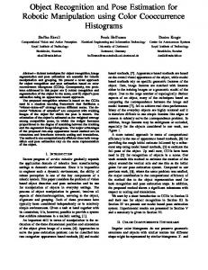
Unlike CCD sensors, CMOS sensors are well suited for embedded applications and have several acquisition modes. One of these modes makes them cheap as its electronics is simpler and allows for higher frame rate. This mode exposes the scan-lines of the sensor sequentially and is called rolling shutter. We call a camera using it a rolling shutter camera. These cameras create distortions in the image when an object or the camera moves during image acquisition. The object or scene may appear curved or leaned depending on the motion. An example is shown in figure 1. Most computer vision methods deal with global shutter cameras whereby all the sensor pixels are exposed at once. These methods do not model the distortions resulting from the rolling shutter acquisition mode. Methods exist to compensate for the rolling shutter effect [1–3]. Instead of compensation, it was shown recently that modelling the relationship between image distortions and object or camera motion allows one to estimate the motion from a single image of a calibrated rolling shutter camera [4–6]. This assumes the kinematics to be constant during image acquisition leading to the uniform rolling shutter camera model. The parameters’ estimation is done using local iterative optimization initialized by the global shutter model. This model has been successfully used in robotics to track a moving object [7]. Since it requires an initialization, the tracking has
2
L. Magerand, A. Bartoli, O. Ait-Aider, and D. Pizzaro
(a) Still fan.
(b) Rotating fan.
(c) Still box.
(d) Translating box.
Fig. 1. Examples of image distortions created by rolling shutter cameras.
to start from a known position and velocity. This model has also been extended to stereo rig [8] and non uniform models also exists [9], still based on local optimization. As an alternative to iterative approaches, we propose to use constrained global optimization of a polynomial objective function in the rotational parameters. We called this polynomial uniform rolling shutter. This is obtained using Taylor expansion of Rodrigues’ formula and elimination of the translational parameters. The optimization results from the Generalized Problem of Moments approach taken in GloptiPoly 3 [10]. The resulting Semi Definite Programming problem is solved using Csdp [11] for performance reason. Contrarily to previous work, our approach does not need an initialization, ensures that the global minimum is achieved and enforces the constraints exactly. This allows us to use this model to match automatically 2D projections with 3D object points and to estimate position and velocity without any prior knowledge. Manually and randomly generated simulations have been used to study our model behaviour and the matching. This allows us to define empirically a validity domain for Rodrigues’ formula approximation, which shows to be large enough to cope with practical motion. With or without automatic matching, increasing noise level makes the error to grow, especially on the dynamic parameters representing the motion. Knowing correspondences, the estimation error with respect to ground truth decreases when using more data points to estimate the parameters. This leads to a growth of the error when using automatic matching and a lot of outliers as there are less points available for the estimation. Our approach generally outperforms previous ones, is more robust to moderate noise and allows for automatic correspondences. Two real sequences were used to test the estimation method and two others to demonstrate the 2D-3D matching. Paper organisation. Section 2 gives background on both the global shutter and uniform rolling shutter camera models. Section 3 introduces our polynomial uniform rolling shutter camera model. Our estimation method is given in section 4 and experimental results are reported in section 5. Section 6 will give an example of application trough automatic and robust 2D-3D matching. Notation. Scalars and indices are in italics (e.g. c). Vectors are column matrices noted in bold (e.g. v). Other matrices are in sans-serif (e.g. M). The 3D rotation matrix group is denoted SO(3) and R is the set of real numbers. The homogeneous coordinates of a point w are written ˜ The symbol ∼ represents homogeneous equality. The skew symmetric matrix associated to w. v ∈ R3 is noted [v]× . The Moore-Penrose pseudo-inverse of matrix M is written M+ . The identity and null matrices or vector are respectively noted I and 0 or 0.
2
Background and Previous Work
The perspective projection model we use is the classical calibrated pin-hole projection [12, 13]. We suppose the geometry of the 3D object to be known and correspondences between its n 3D points and their 2D projections in the image to be given. They are indexed by i ∈ [1; n].
Global Optimization of Object Pose and Motion from a Single Rolling Shutter Image
2.1
3
Global Shutter
Global shutter cameras expose all scan-lines simultaneously. A 3D point pi is projected to the 2D image point mi = [ui , vi ]> as ˜ i ∼ K[ R | t ]p ˜ i, m (1) where R ∈ SO(3) and t ∈ R3 are the rotational and translational parts of the object pose. Assuming rectangular sensor elements then the internal calibration matrix is αu 0 u0 K = 0 αv v0 , (2) 0 0 1 where αu and αv are horizontal and vertical scale factors and [u0 , v0 ]> is the principal point. These parameters are typically estimated using static calibration algorithms [14–16]. In general, given K and at least four object points with their corresponding measured image projections, the object pose (R, t) can be uniquely estimated [12, 17, 13]. Using only three points gives up to four solutions.
Fig. 2. The uniform rolling shutter camera model.
2.2
Uniform Rolling Shutter
A uniform rolling shutter camera model can be obtained by extending the global shutter camera model [4]. Let (R1 , t1 ) be the unknown pose of the object when the first scan-line of the image is exposed. The kinematics of the moving object are the translation velocity vector v and the rotation speed ω around a unitary axis a. They are assumed constant during the image acquisition. The known time between exposition of two consecutive scan-lines is noted τ . Therefore the scan-line vi onto which point pi is projected is exposed at time τi = vi τ . The uniform rolling shutter projection model is illustrated in figure 2 and derived from equation (1) as ˜ i ∼ K [R1 δR(τi , a, ω) | t1 + δt(τi , v)] p ˜ i, m (3) where δt(τi , v) = τi v and δR(τi , a, ω) is given by Rodrigues’ formula [18] δR(τi , a, ω) = aa> (1 − cos(τi ω)) + I cos(τi ω) + [a]× sin(τi ω).
(4)
4
L. Magerand, A. Bartoli, O. Ait-Aider, and D. Pizzaro
In [4], the kinematics and initial pose are estimated by minimizing the reprojection error. This non-convex optimisation problem is solved using an iterative and local method, which is initialized using the global shutter model for (R1 , t1 ) and some constant arbitrary values for v, a and ω. Rotation R1 is parametrised with a quaternion. The resulting unitary constraint and the one on a are added to the objective function with an empirical normalization coefficient. The same model and method have been used in robotics to track a moving object [7], aiming at visual servoing. In order to get the 2D-3D correspondences during the tracking, the position of the projections in the next frame are predicted using the estimation of the kinematics from the current frame. This requires the correspondences to be known in the first image of the sequence, as well as the object initial position and velocity.
3
Polynomial Uniform Rolling Shutter
Using an approximation of Rodrigues’ formula, the non-linear uniform rolling shutter model used in [4] can be transformed into a polynomial model. Considering n correspondences, this gives a system of 2n degree two polynomial equations with 12 unknowns subject to six quadratic and one degree three constraints. 3.1
Rodrigues’ Formula Taylor Expansion
Assuming the products {τi ω}i∈[1;n] to be small and defining w = ωa, the first order Taylor expansion of sin and cos gives a polynomial approximation of Rodrigues’ formula δR(τi , w) = I + τi [w]× .
(5)
The domain of validity of this expression will be studied in section 5.1. The unknown vector w contains the rotational speed parameters ω and a which may be extracted from w using ω = kwk and a = w/ω. 3.2
(6)
Polynomial Reprojection Error
˜ i = K−1 m ˜ i = [fi , gi , 1]> be the coordinate of m ˜ i expressed in the camera frame. We rescale Let d the time-line so that τ1 = 0 and define (R0 , t0 ) to be the unknown object pose at this instant. We use the direct parametrisation of R0 as this lowers the degree of the reprojection error and thus is more efficient compared to others rotation parametrisations. Using Taylor expansion of Rodrigues’ formula, one obtains the polynomial uniform rolling shutter model as ˜ i ∼ N [ R0 + τi R0 [w] | t0 + τi v ] p ˜ i, Nd × {z } | {z } | =Ri
(7)
=ti
where N is a data normalizing transformation composed of a translation to make the origin √ being the centroid and an isotropic rescaling so that the average distance to the origin is 2. This matrix looks like γ 0 −γµu N = 0 γ −γµv . (8) 00 1
Global Optimization of Object Pose and Motion from a Single Rolling Shutter Image
5
One can obtain the algebraic reprojection error using the cross product to get rid of the homogeneous equality: � � 100 h ˜ i Ndi N[Ri |ti ]˜ pi = 0, (9) hi = 010 × | {z } =S
where S is used to remove the dependency between the third line and the two firsts. Considering n correspondences, the polynomial system of equations to satisfy is given by � > h1 = 0 R0 R0 = I .. s.t. (10) . |R0 | = 1. hn = 0
4
Solving the Polynomial System
Provided we have enough point correspondences, the polynomial system (10) can be solved using constrained global optimization. This is done after elimination of the translational parameters. The objective function is a degree four polynomial in twelve unknowns (the rotational parameters). 4.1
Translational Parameter Elimination
The nine entries of Ri are degree two polynomials in the rotational parameters (R0 and w). Let ρi be its vectorization and η i be the vectorization of ti . One can notice from the definition of ti that � � > > η i = Ci t> with Ci = [I|τi I]. (11) 0 |v Equation (9) can then be rewritten as � � > > hi = Ai Nd ρi + Bi Nη i = 0 ⇔ Bi NCi t> = −Ai Nd ρi , 0 |v
(12)
where Ai and Bi are respectively 2 × 9 and 2 × 3 matrices whose coefficients depend on di and pi , the later being used only in Ai . Matrix Nd is the block diagonal concatenation of N repeated three times. Using n ≥ 3 point correspondences, t0 and v are therefore solutions of the linear system � � > > D t> = −Aρ, 0 |v
(13)
where D is the vertical concatenation of {Bi NCi }i∈[1;n] , A is the block diagonal concatenation of {Ai Nd }i∈[1;n] , and ρ is the vertical concatenation of {ρi }i∈[1;n] . Assuming the scan-lines of all the 2D projections to be different, then D is full rank because of its structure and � > > �> t0 | v = −D+ Aρ. 4.2
(14)
Rotational Parameter Optimization
Substituting η i in equation (12) using equations (11) and (14) results in hi = Ai Nd ρi − Bi NCi D+ Aρ = 0.
(15)
6
L. Magerand, A. Bartoli, O. Ait-Aider, and D. Pizzaro
Only the rotational parameters R0 and w are involved in this equation. They can be estimated using the n point correspondences by constrained global polynomial optimisation � > R0 R0 = I + 2 min k (A − DD A) ρ k , s.t. (16) |R0 | = 1. {R0 ,w} There exists tools such as GloptiPoly 3 [10] that handle this type of optimisation. This is based on the resolution of the Generalized Problem of Moments. It results in a Semi Definite Programming problem easily solved using Csdp [11] for performance reason. This requires that there is only one global minimum and thus at least seven correspondences, as noticed experimentally in section 5.1. Once the rotational parameters have been estimated, ω and a may be extracted from w using (6) and the translational parameters may be retrieved from equation (14). 4.3
Practical Details
With really small values of {τi }i∈[1;n] , which is needed by the Taylor expansion of Rodrigues’ formula, the matrix D might become ill-conditioned. Scaling the time-line using λ = mean({τi }i∈[1;n] ) solve this numerical instability. This is equivalent to rescaling the motion parameters with 1/λ and can be easily undone after the optimisation.
5
Experimental Results
We evaluated our approach using simulated and real data. In this section PURS stands for our proposed model and URS denotes the model proposed in [4]. We note GS the global shutter model. 5.1
Simulated Data
The first data set simulates the projection of three faces of a cube with manually chosen camera and dynamic parameters. Translational and rotational motions with various velocities are simulated. The same camera and dynamic parameters were also used to project points randomly placed. There is a total of 34 simulations in this set. The second data set is made of 113 simulations with random camera and dynamic parameters. Each simulation is repeated with τ being 10−5 , 10−6 and 10−7 seconds. The simulations are done following the same idea as in [3]. For each line we project the object points with the pose of this line obtain from (3), and keep only those projected onto the line.
10
rel err (%)
8
data points fitted polynomial
6 4 2 0 0
0.01
0.02 0.03 τnω (rad)
0.04
0.05
Fig. 3. Relative error on the parameters with respect to τn ω. The approximation seems to hold well until τn ω < 0.05, which corresponds to error usually under 5%. Using correct camera parameters, this is large enough for any practical motion.
Approximation Validity The first set of experiment gives the domain into which the approximation of Rodrigues’ formula holds. From the complete simulated data set, we fitted a degree two
Global Optimization of Object Pose and Motion from a Single Rolling Shutter Image
7
polynomial over the root mean square relative error on the parameters with respect to the value of τn ω. This corresponds to the rotation angle of the last projected point, which is the maximum one. Degree two polynomial is used because this is the degree of the next leading terms in the Taylor expansion of Rodrigues’ formula. Figure 3 shows the result of this experiment. Generally vi < 2000, ∀i ∈ [1; n], and τ can be as low as 10−8 seconds on very high speed CMOS cameras. Empirically τn ω have to be less than 0.05 in order to keep the error under 5%, this allows rotation velocity up to ten thousand rotations per minute.
6
6
Static PURS Dyn. PURS Static URS Dyn. URS
5
4
||v|| = 12.4, ω = 2.0, max(|vi τ ω|) = 0.01808
Static PURS Dyn. PURS Static URS Dyn. URS
4 3 2
Static PURS Dyn. PURS Static URS Dyn. URS
7 6 relative error
relative error
8
||v|| = 47.2, ω = 3.1, max(|vi τ ω|) = 0.02954
||v|| = 302.0, ω = 36.0, max(|vi τ ω|) = 0.03627
relative error
10
5 4 3 2
2 0 6
1 7 8 9 10 12 15 20 25 30 number of points
40
50
(a) Cube quickly rotating and translating, average exposure time.
0 6
1 7 8 9 10 12 15 20 25 30 number of points
40
50
(b) Random points rotating slowly and translating quickly, long exposure time.
0 6
7 8 9 10 12 15 20 25 30 number of points
40
50
(c) Random points slowly rotating and translating, long exposure time.
Fig. 4. Examples of relative error curves with respect to the number of points used for the estimation. The error decreases with the number of points. Usually our PURS approach outperforms the URS method. The error with GS is generally at least an order of magnitude larger than those of PURS and URS.
Effect of the Number of Points Used Figure 4 shows the relative error on the parameters with respect to the number of points used in their estimation. Usually the relative error on the dynamic parameters are at least an order of magnitude higher than the one on the static parameters. This is due to the coefficients of the dynamic parameters in the objective function which are square values of the measured data. For this reason, the relative error is given as permille for the static parameters and as percent for the dynamic parameters. Using 6 or 6.5 points usually leads to incorrect results. This is expected as we need three points to estimate the dynamic parameters and the static parameters needs at least four points to be uniquely determined as seen in section 2.1. Between seven to twelve points the relative error is decreasing quickly With more than twelve correspondences, the error is slowly decreasing or nearly stable for both methods. With at least seven points, usually our method outperforms previous work.
Effect of Gaussian Noise Here we study the effect of a Gaussian centred noise added to the 2D projections in the image. The noise level is varied from 0.01 to 2 pixels. The curves of the relative error with respect to the noise level are given in figures 5(a) and 5(b). As already noticed in section 5.1, the dynamic parameters are more sensitive to noise than the static parameters. The error on these parameters quickly becomes very high with both approaches, although the PURS method is a bit more resistant generally. With noisy data, increasing the number of points decreases the error, as shown in figure 5(c).
8
L. Magerand, A. Bartoli, O. Ait-Aider, and D. Pizzaro ||v|| = 330.3, ω = 256.0, max(|vi τ ω|) = 0.00007
25 20 15 10
8 6 4
Static PURS Dyn. PURS Static URS Dyn. URS
10
5
2
5 0 0
σ = 0.50000, ||v|| = 330.3, ω = 256.0, max(|vi τ ω|) = 0.00007 15
Static PURS Dyn. PURS Static URS Dyn. URS
10 relative error
relative error
30
||v|| = 13.5, ω = 23.0, max(|vi τ ω|) = 0.00052 12
Static PURS Dyn. PURS Static URS Dyn. URS
relative error
35
0.5
1 noise level (pixel)
1.5
2
(a) Cube quickly translating and rotating with low exposure time.
0 0
0.5
1 noise level (pixel)
1.5
2
(b) Cube slowly translating and rotating at medium velocity, average exposure time.
0
10
15
20 25 30 35 40 45 50 58 number of points
(c) Random points quickly moving, low exposure time and noise level of 0.5 pixel.
Fig. 5. Examples of relative error curves with respect to noise level or number of points. The error on dynamic parameters grows quickly with the noise leve for all methods, although PURS is a bit more robust. Using more data points improves the estimation.
5.2
Real Data
Our method is compared with previous work using two sequences filmed using a PixeLINK PL-B771 rolling shutter camera. One shows an object undergoing a nearly pure fronto-parallel rotation and the other a nearly pure translation. These two simplest motion were used in order to evaluate the deviation to the real motion without having ground truth.
GS URS PURS data
(a) Rotating object.
GS URS PURS data
(b) Translating object.
Fig. 6. Reprojections obtained from GS, URS and PURS with real data.
First Sequence The object is undergoing a nearly pure fronto-parallel rotation. This sequence is made of 28 images featuring 17 points with known correspondences. One of these images and the corresponding reprojection are shown in figure 6(a). On figure 7(a), we fitted a circle through the estimated translations of seven consecutive images with high velocity. As the error between the estimation and the fitted circle is 21mm with the URS approach and 0.4mm with the PURS method, the later is more coherent with a rotational motion. The PURS approach also better fits the fronto-parallel placement of the camera as the standard deviation on the depth axis is only 2.8mm whereas it is 30mm with the URS method. Second Sequence A box undergoing a manual translation guided by a rail is filmed. There is 16 correspondences in this sequence of ten images. An example of reprojection for this sequence is
Global Optimization of Object Pose and Motion from a Single Rolling Shutter Image
0.8
9
PURS velocity URS velocity
PURS velocity PURS circle URS velocity URS cirle
z
0.7 0.6
5
0.5
0
0.4 −0.1
0.1 −0.05
0 0
0.05
0.1 −0.1
−0.5
−5 −1
0 0 1
y
x
(a) Rotation motion fitted on a circle.
2 0.5
(b) Translation motion fitted on a line.
Fig. 7. Motion parameters estimated on real data: this is consistent throughout the frames and represents closely the real motion.
given in figure 6(b). The estimated translation velocity are shown in figure 7(b). We fitted a line through the translations and table 1 shows that the PURS method outperforms the URS approach as it fits better to a nearly pure translational motion: quasi-static rotations and translations following a straight line. Table 1. Average distance of the translations to the fitted line, average angular velocity and mean standard deviation of the rotation Euler angles through the sequence with a nearly pure translation motion. The lower this values, the better the estimate is with respect to the real motion.
6 6.1
URS PURS distance (mm) 16 4.4 velocity (rad/s) 13 2.7 std dev. Eul (rad) 1.3 0.04
Automatic 2D-3D Correspondences Description of the Method
An initial correspondences set is obtained from a SIFT [19, 20] matching between a template of the object without motion and the current frame. In order to process real data, an accurate 3D model of the object is needed. We used global shutter stereo reconstruction from a calibrated stereo rig to obtain such a model, choosing one of the views as the template and keeping the SIFT descriptors used during the reconstruction for matching with the current frame. Particular care must be taken in choosing the various thresholds in RANSAC. The error used to select the inliers can’t be computed from equation (15) as the pseudo inversion used to eliminate the translational parameters might cause the rows to be exchanged. Using the initial reprojection error from equation (9) solves this issue. 6.2
Experimental Results
Simulated Data Using the same simulated data as in section 5.1, the response to noisy data has been verified again. On figure 8(a), the same effect as previously can be observed: error grows quickly with noise, especially on the dynamic parameters. There was 5 known outliers in the 40 points considered in these experiments, which were correctly filtered out by RANSAC every
10
L. Magerand, A. Bartoli, O. Ait-Aider, and D. Pizzaro
100
Static trans. Dyn. trans. Static rot. Dyn. rot.
30 25 relative error
80 relative error
35
Static trans. Dyn. trans. Static rot. Dyn. rot.
60 40
20 15 10
20 5 0 0
0.5
1 noise level (pixel)
1.5
0 0
2
(a) As when knowing the correspondences, error grows with the noise level. Dynamics parameters are less robust.
10
20 30 outliers percentage
40
50
(b) The error increases when the percentage of outliers grow. This is expected as there are less points left for estimation.
Fig. 8. Relative error on the parameters with respect to the number of outliers or the noise level.
time. The outliers were obtained by changing some of the correspondences to produce virtual outliers. About one half of them were mismatched points and the other part were set to random 2D projection. We also studied the behaviour with respect to the number of outliers and a small constant level of noise about a tenth of a pixel on all projections. The outliers percentage has been varied from 2% up to 50% on a total of 40 points. Results from this experiment is given in figure 8(b). As the percentage of outliers increases, the error on the parameters’ estimation with respect to the ground-truth also increases. This is expected as there are less points left to estimate the parameters once the outliers have been filtered and as shown previously, with noisy data the error increases when there is less points available. Despite a small number of iterations allowed (one thousand), the correct set of inliers has been found every time.
13
Static Reproj. Data Points Velocity13 23
23
22
57
5
11 18 9 10 12 2 6 14 816 15 21 4 119 3 17 20
7 11
18 9 6
1 19
2 14 816 15
34
10 12 21
17
22 20
(a) The template
(b) First image
(c) Second image
(d) Third image
Fig. 9. A box falling in front of a rolling shutter camera (b-d) and its template (a). The object and its estimated velocity has been reprojected on (c) with the static pose estimation. Despite there is still two outliers, the motion is really close to being the real one as it’s nearly vertical and the estimated velocity is about 2.1m/s after less than one third of a second of free fall. On the first and third image, there was not enough points detected to robustly rebuild correspondences and estimate the model parameters.
Global Optimization of Object Pose and Motion from a Single Rolling Shutter Image
11
Real Sequences We started by dropping a box in front of a rolling shutter camera as seen in figure 9. The 3D reconstruction of the box model used around eighty points which were available for matching. The resulting motion is a vertical translation shown in figure 9(c). Despite the frame rate being 48f ps, the motion was fast enough for the object to appear only on three consecutive frames and being seen entirely in only one. Figure 10 shows a sequence of four image exhibiting a rotating box which decelerate. Less than forty points were available in the 3D model of this object. The estimated velocity has been reprojected at the object centroid on each image. On image two and four, the results are really accurate and coherent with the motion. In the third image, the direction of the velocity is biased by an outlier not filtered out probably due to the various thresholds in RANSAC not being optimal. The estimation mostly failed on the first image due to the initial set of correspondences being too small and with a lot of outliers (more than 80%). Another longer sequence featuring a cup in a planar motion is presented as supplementary material. Many more feature points are observed in the frames, therefore the robust estimation failed less often. The planar motion has been recovered correctly in most of the frames. Velocity
(a) First (12.17rad/s)
Velocity
image (b) Second (8.96rad/s)
Velocity
image (c) Third (3.76rad/s)
Velocity
image (d) Fourth (1.34rad/s)
image
Fig. 10. A box rotating initially at 12.5rad/s and decelerating through a sequence of four images. The estimated rotational velocity given in each image caption and reprojected at the object centroid is coherent with this motion on image two to four. However, an outlier was not detected on the third image and therefore the estimation is not as good as the ones in the second and fourth image. The rotational velocity is still correctly estimated, but its direction has been biased by the outlier. The suboptimal thresholds and iteration limit in RANSAC might be responsible. In the first image the optimisation failed as there was not enough points in the initial matching and a lot of wrong correspondences.
7
Conclusion
The distortions created by rolling shutter cameras give more information in a single image than global shutter cameras, and usually with a lower cost. Knowing the geometry of the object and correspondences with its projection on a single template, they can be used as a motion sensor. All this gives to these cameras a very wide interest. Assuming the object motion to be uniform and using a polynomial approximation of Rodrigues’ formula, we proposed a method to estimate the uniform motion using constrained global optimization of a polynomial objective function. The optimization is done using the Generalized Problem of Moments method from GloptiPoly 3 and the resulting Semi Definite Programming problem is solved using Csdp. The estimation has been tested and compared to previous work. As our method ensures that the global minimum is found and the constraints perfectly satisfied, it usually outperforms previous methods and allowed us to build automatically robust 2D-3D correspondences. Knowing these correspondences, the behaviour with noisy data has been studied as well. Although the
12
L. Magerand, A. Bartoli, O. Ait-Aider, and D. Pizzaro
static parameters are quite robust to noise, the motion parameters are highly sensitivity for all approaches. This result was also confirmed when building the correspondences automatically. Furthermore, we showed results on real data that exhibit estimated parameters coherent with the real motion. Matching the 3D object points with the 2D projection using a template has been demonstrated on real data. The method does not behave as well with actual data as with simulated one but is still able to recover the motion correctly most of the time. There is still a lot of work to do that would allow to obtain greater results from this method on real data. Because the estimation is quite sensitive to noise, improving localisation of the features points in rolling shutter images would massively reduce the final estimation error. Obtaining larger inliers set free of any outliers with automatically enhanced thresholds would even improve a lot the results.
References 1. Bradley, D., Atcheson, B., Ihrke, I., Heidrich, W.: Synchronization and rolling shutter compensation for consumer video camera arrays. In: PROCAMS. (2009) 2. Liang, C., Chang, L., Chen, H.: Analysis and compensation of rolling shutter effect. IEEE Trans. on Image Processing (2008) 3. Forssén, P.E., Ringaby, E.: Rectifying rolling shutter video from hand-held devices. In: CVPR. (2010) 4. Ait-Aider, O., Andreff, N., Lavest, J.M., Martinet, P.: Simultaneous object pose and velocity computation using a single view from a rolling shutter camera. In: ECCV. (2006) 5. Ait-Aider, O., Bartoli, A., Andreff, N.: Kinematics from lines in a single rolling shutter image. In: CVPR. (2007) 6. Meingast, M., Geyer, C., Sastry, S.: Geometric models of rolling-shutter cameras. CoRR (2005) 7. Dahmouche, R., Ait-Aider, O., Andreff, N., Mezouar, Y.: High-speed pose and velocity measurement from vision. In: ICRA. (2008) 8. Ait-Aider, O., Berry, F.: Structure and kinematics triangulation with a rolling shutter stereo rig. In: ICCV. (2009) 9. Magerand, L., Bartoli, A.: A generic rolling shutter camera model and its application to dynamic pose estimation. In: 3DPVT. (2010) 10. Henrion, D., Lasserre, J., Loefberg, J.: Gloptipoly 3: moments, optimization and semidefinite programming. Optimization Methods and Software (2009) 11. Borchers, B., Young, J.G.: Implementation of a primal–dual method for sdp on a shared memory parallel architecture. Computational Optimization and Applications (2007) 12. Hartley, R., Zisserman, A.: Multiple View Geometry in Computer Vision. Cambridge Univ. Press (2004) 13. Paragios, N., Chen, Y., Faugeras, O.: Handbook of Mathematical Models in Computer Vision. Springer (2006) 14. Heikkila, J., Silvén, O.: A four-step camera calibration procedure with implicit image correction. In: CVPR. (1997) 15. Tsai, R.: An efficient and accurate camera calibration technique for 3D machine vision. In: CVPR. (1986) 16. Zhang, Z.: Flexible camera calibration by viewing a plane from unknown orientations. In: ICCV. (1999) 17. Lepetit, V., Moreno-Noguer, F., Fua, P.: Epnp: An accurate O(n) solution to the PnP problem. IJCV (2009) 18. Murray, R.M., Li, Z., Sastry, S.S.: A Mathematical Introduction to Robotic Manipulation. CRC Press Inc. (1994) 19. Lowe, D.G.: Distinctive image features from scale-invariant keypoints. IJCV (2004) 20. Vedaldi, A., Fulkerson, B.: VLFeat: An open and portable library of computer vision algorithms. http://www.vlfeat.org/ (2008)