World Academy of Science, Engineering and Technology 46 2008
Hot-Spot Blob Merging for Real-Time Image Segmentation K. Kraus, M. Uiberacker, O. Martikainen, and R. Reda watershed [4]. Despite introducing general purpose algorithms, no optimal solution for image segmentation has been found. The algorithms heavily depend on domain knowledge and problem-specific optimizations. A combination of methods seems promising to minimize the inherent disadvantages of each algorithm. On the one hand, region growth suffers from the tendency to cover multiple overlapping objects whereas model based algorithms tend to become unreliable when unwanted artifacts, like shadows and reflections, show up in the scene. Also the mean shift clustering algorithm [5], used to find the local maxima, is susceptible for covering multiple overlapping objects especially in crowded scenes [6]. Furthermore the mean shift results have been shown to be inconsistent in subsequent frames; this deteriorates post processing steps like object tracking. State-of-the-art automated video surveillance systems have increasing complexity to meet the high standards expected by today’s customers, with respect to true- and false-positive rates, while being robust against environment changes. With the rapid increase of processing power of modern computers image analysis algorithms, which have been too complex can now be implemented in real time. However when implementing the whole algorithmic pipeline needed for stateof-the-art automated video surveillance systems the resources for a single algorithm are still limited. Currently available CCTV systems are based on traditional per pixel analysis which limits either the image resolution or the count of operations per frame that can be performed. Recent publications on the topic on background modeling proposed pre-defined image regions (hence called blocks) to allow more complex analysis; the same methodology can be applied for image segmentation. Due to the reduction of resolution the algorithm presented in this work can be used in conjunction with a pixel based segmentation algorithm (e.g. mean shift).
Abstract—One of the major, difficult tasks in automated video surveillance is the segmentation of relevant objects in the scene. Current implementations often yield inconsistent results on average from frame to frame when trying to differentiate partly occluding objects. This paper presents an efficient block-based segmentation algorithm which is capable of separating partly occluding objects and detecting shadows. It has been proven to perform in real time with a maximum duration of 47.48 ms per frame (for 8x8 blocks on a 720x576 image) with a true positive rate of 89.2%. The flexible structure of the algorithm enables adaptations and improvements with little effort. Most of the parameters correspond to relative differences between quantities extracted from the image and should therefore not depend on scene and lighting conditions. Thus presenting a performance oriented segmentation algorithm which is applicable in all critical real time scenarios.
Keywords—Image segmentation, Model-based, Region growing, Blob Analysis, Occlusion, Shadow detection, Intelligent video surveillance.
I
I. INTRODUCTION
MAGE segmentation algorithms used to partition a digital image into multiple regions are essential in numerous applications including medical imaging, face recognition, fingerprint recognition and machine vision. Accordingly several general-purpose algorithms have been developed. These algorithms can be divided into categories depending on the technique used for segmentation. One category is based on density or colour histograms where peaks and valleys in the histogram distribution are used to locate clusters [1]. Another method called region growing starts by so called seeds and iteratively grows regions by comparing all unallocated neighbouring pixels to the seed value. Edge detection is used as well in this field as objects tend show strong differences in intensity at the region boundaries. Model based segmentation on the other hand works on the assumption that domain-relevant objects show within some minor variations - a unique form of geometry. Apart from these techniques other algorithms have been proposed including level-set [2], graph partitioning [3] and
II. HOTSPOT BLOB IMAGE SEGMENTATION This work presents an image segmentation algorithm which uses a block based to reduce the image resolution (with keeping all relevant information) and in turn down-scales problem complexity and processing performance. In this work the term “block” is used in a very general way and stands for a certain image area. It can range from a single pixel to a square or even rectangular image part containing multiple pixels. The block size should be chosen to be
Klemens Kraus is with Kiwi Security, Vienna, Austria (phone number: +43 - 650 – 4419172; e-mail:
[email protected]). Matthias Uiberacker is with Kiwi Security, Vienna, Austria (e-mail:
[email protected]). Olli Martikainen is with the University of Oulu, Department of Information Processing Sciences, Oulu, Finland (e-mail:
[email protected]). Reda Reda is with Innovation Communication Technologies, Austria / Germany (e-mail:
[email protected]).
430
World Academy of Science, Engineering and Technology 46 2008
significantly smaller than then the expected object size to have sufficient resolution for analysis and tracking. A block size of 8x8 pixels was found to be the optimal trade-off between loss of resolution and computing performance determined by empirical tests. Furthermore the block size is kept constant within the whole image and over time. This method can be integrated into background models (used to distinguish between fore- and background image areas) that also commonly use blocks to improve - in the same way - the performance of the foreground detection in complex scenes including lighting changes and/or moving objects in the background. Each block is represented by the following data: I: The index of the block. It holds the unique position within the image similar to an index in a one-dimensional array.
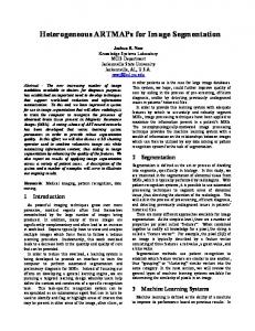
For the unprocessed image a block starts out with Sb = unassigned, Wb = 0, Ab = 1, Rb = ‘no reference’; this is called the pre-processing stage. Throughout the stages of the algorithm Sb can change to one of the following states: irrelevant, relevant, assigned, center, joined center and junction, where all states but relevant are possible final states (see Fig. 1). When the background model designates a block as background, this block is no longer relevant for the algorithm and thus labeled as irrelevant, on the other hand if the background model flags the block as foreground it is tagged as relevant. Only relevant blocks are considered for further calculations and can either become center blocks if a certain amount of neighboring blocks has the correct state, which is an indication that the location of the block may be part of a new blob within the image, or assigned if the block is in close proximity to another block that belongs to a center. Furthermore blocks that connect areas of different assignments will be labeled as junction. Finally the different parts connected by junctions can be bridged or separated due to certain rules derived from their characteristics forming a bigger blob or splitting blobs into smaller segments. A. The Algorithmic Stages The algorithm is performed in stages numbered from one to six. A pre-processing stage is also introduced which resets any information contained in the blocks used in a previous frame. This allows the minimization of allocations which improves the performance. Stage 1: The algorithm starts by calculating the integral sum of intensities of all blocks (SoI) deemed relevant by the background model, places the SoI into the Wb variable for each block and builds a list for these blocks. The list is sorted by Wb where the highest Wb is the first element the second the second highest and so on. If Wb is below a certain threshold tI a block is completely discarded and sets Sb = irrelevant, therefore the list only contains blocks with Sb = relevant. Stage 2: For each block in the list, starting by the first, Sb is checked. If Sb ≠ relevant it means that the block has already been assigned to a center and doesn’t need to be processed in this step. Otherwise the block is processed and all block states in the neighborhood are checked. The neighborhood is a possible design parameter of the algorithm and can include only the adjacent blocks (as implemented in this work) or also blocks farther away. Depending on the implementation the algorithm does an iterative check of how many neighbors are found with Sb = relevant. In the first iteration it checks if it finds a block within the image where all neighbors are in relevant state. If this holds true the block is labeled as center (Sb = center) and all neighboring block states are changed to Sb = associated. Furthermore Wb of every associated neighbor is added to the weight of the center block Wc.
Fig. 1 Stage diagram illustrating possible block states and state changes. Bold states designate end states
Sb: The state of the block. It influences the algorithmic behaviour and can change throughout the algorithm. Possible states can be seen in Fig. 1. Wb: The weight of the block corresponding to the integrated intensity within the block’s area. Ab: The covered image area in units of blocks. It starts with one and is incremented for blocks with certain states as the blob size increases. Rb: The reference to another block. It can link one block to another block.
431
World Academy of Science, Engineering and Technology 46 2008
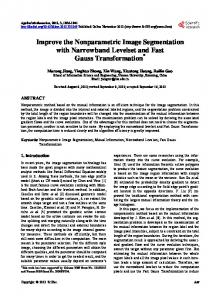
Fig. 1 Block states for the different algorithmic stages: a, original image; b, differential image calculated by the background model; c, classification of blocks into relevant (white) and irrelevant (black) blocks; d, labeling centers (green) and associated (red) blocks; e, labeling junctions (blue); f, conversion of centers to joined centers (yellow); g, cancellation of shadow blocks (gray); h, the final bounding boxes of the objects
If one or more blocks are found to already be associated the algorithm proceeds by finding all corresponding centers and associates the current block to the center with the highest Wc. This corresponds to setting Sb = associated, storing the center’s address in Rb and add Wb of the current block to Wc. Should the first iteration yield no centers at all (and therefore no associations as well) the number of neighbors needed to form a center decreases and the iterative search for centers and associations continues until all blocks are either a center or associated.
the final center of a blob can be found simply by traversing the center reference chain from any block until the reference doesn’t change anymore. Stage 5: A new object called “blob” is introduced, which essentially holds the relevant data of one segmented region within the image. A blob object consists of the following data: Lblob: A list of blocks belonging to it (and sharing the same center). Cblob: The final center of the blob. BBblob: The coordinates of the final bounding box (left, right, lower, upper border). Wblob: The total weight of the blob. Ablob: The total area of the blob. A last time the list of blocks is traversed to create one blob per center and store all associated blocks in the reference list.
Stage 3: After labeling and associating the blocks, possible borderlines (junctions) between the regions of different centers have to be found. The list containing the relevant blocks is traversed once more and all blocks that are in associated state and have one or more blocks with different center references in their neighborhood are marked as junction. To manage the weight of the junctions a junction object is introduced; it holds references Rj,1 , Rj,2 to two center blocks, a weight Wj and an area Aj. The junction objects are identified by the two references and stored in a list. If a block is part of a junction, the list of junctions is iterated to find the corresponding object. If no corresponding references are found in the list, a new junction is created with Wj = 0 and Aj = 0 and appended to the list. In either case, the weight and area of the current block is added to the values of the junction.
Stage 6: Due to static occlusions within the scene or object parts with very similar color to the background image, an object can be split into two or more blobs. To avoid this unwanted behavior we implemented a simple model-fitting algorithm based on the shape of a human approximated by a rectangle. The dimensions of the model are manually calibrated at three distinct positions in the image and interpolated in between for every other position (barycentric interpolation). As the head (or top) regions of the objects are the most stable areas (generally fixed with respect to the object’s center and mostly free from shadows) we sort the list of blobs according to their y-coordinate starting with the uppermost blobs (low y-coordinate). A rectangular shaped acceptance area is positioned with congruent upper border to the bounding box BBblob. Furthermore the acceptance area is placed horizontally with an offset to the center of BBblob. The offset depends on the perspective of the scene which yields shear/rotation of the objects and the size of the acceptance
Stage 4: After finishing the search for blocks being part of a junction the list of junctions is sorted according to Wj. If the junction is found to be of relevance (e.g. by comparing to a threshold tJ or by analyzing the balance of weights of the two centers with respect to the junction weight) the centers shall be joined. In this case the state of the center with less weight (the weak center) is changed to joined center and the reference is updated to point to the second center (the strong center) which effectively merges the two centers in an efficient way. Now
432
World Academy of Science, Engineering and Technology 46 2008
area. The offset value is calibrated by hand at the left and right border of the scene and linearly interpolated between these positions. If any other blob has ample overlap with the acceptance area, this blob is joined to the “accepting” blob and then deleted from the list of blobs. Ample overlap is given if kO percent of the blob’s bounding box is within the acceptance area (kO = 50% was chosen in the current implementation).
mechanism. It significantly reduces the perturbing amount of shadows while keeping objects with a generally low density in the difference image. After processing all blocks in this way, the bounding box is defined for this blob. This procedure offers the advantage of using the already computed values also needed for the main algorithm which results in an easy to implement and efficient way to detect shadows. Compared to the algorithm defined by Horprasert et al. using an YUV image which needs about 12 ms on the test system the performance impact of this implementation is on average much less with approximately 1.5 ms and maximum 6 ms. It should be stated, that the mechanism can lead to unwanted results when the intensity of the object is generally lower in the difference image than the intensity of the shadow.
Post-processing stage: Here a final filtering of the remaining blobs is performed. Currently two strategies are applied: Firstly the size of blobs being much smaller than the size of a human estimated by the model and secondly an approximated width:height ratio being larger than 1 can yield to the deletion of a blob. The more the computed ratio and size differs from the constraints the lower is the confidence rating; candidates with a confidence rating below a threshold tC are removed. After this stage the remaining blobs can be visualized with a rectangular outline. III. SHADOW CANCELLATION One of the well known problems common in the area of region growth techniques is the tendency to cover multiple independent objects. This characteristic is further enhanced in the case of inaccurate background images containing strong shadows. This behavior is also present in the proposed algorithm and became evident in the scenes tested; shadows were present in the computed difference image which resulted in the merging of multiple persons to a single object. To cancel the perturbing shadows standard shadow cancellation algorithms including Horprasert et al. [7] were considered and tested but proved to provide minimal success. In general either too many areas where eliminated which resulted in the deletion of complete, valid objects because of the different lighting conditions present in different parts of the view, or too few shadows were removed depending on the parameters of the algorithm. Following these considerations a new shadow detection based on the already existing block data was used. The block density: (1) d b = Wb / Ab
Fig. 3 Shadow detection and cancellation. a, original image. b, detected shadow (gray blocks) and blob bounding box (white)
IV. TEST SEQUENCE AND EVALUATION To validate the blob-merging approach the PETS 2006 [8] sequence was chosen, as it is known to show a lot of typical situations in video surveillance including problems like shadows, reflections and occlusions. It should be mentioned that there is currently no implementation of tracking, object association and occlusion handling. Thus the results cannot be directly compared to the officially available ground truth data. To provide a useful measure of the performance of the algorithm, each single frame was checked by hand for false positives. The checks were performed beginning with frame 349 (initialization of background model ended at this point) until frame 2224. After tuning the parameters 202 false positives were found in 1875 frames of the sequence. This corresponds to a true positive rate of 89.2% (see table 1 for details). Most parameters of the algorithm are not depending on absolute quantities and thus should be relatively independent on the chosen test sequence for achieving best results. The high number of ‘object not found’ errors is due to occlusions with static objects in the scene, which are in front of relevant objects and cover a large part of them. The ‘shadow interpreted as object’ errors come from the
where the area is measured in units of blocks, is compared to the density of the center (2) d c = Wc / Ac of every block within a blob. If
db > dc ⋅ kd
(3)
where kd is a constant factor (0.95 in this work), the block’s coordinates are used to update the bounding box to accommodate this block. The same applies, if the maximum intensity value within the block is higher than dc divided by the number of pixels of a block. This ensures that blocks which hold small but bright details are not labeled as shadows (e.g.: at object borders or within small objects). Fig. 3 shows the effect of this
433
World Academy of Science, Engineering and Technology 46 2008
constraint that low intensity objects are not removed from the scene, as this would lead to more ‘object not found’ errors. Therefore all shadows that get separated from their originator and are big enough in size are interpreted as objects.
and shape. Possible variations due to the block-based nature of the algorithm: The size of the blocks can be used to meet the required frame rate. In scenes with high degree of object size variations due to perspective the block size could be changed for certain areas of the image (e.g: upper third with half-size blocks) to increase the resolution. An adaptive block size changing in time or depending on the dimensions of the blobs is also conceivable. Moreover, completely different data might be stored within a block or center (e.g.: textons [9], HOGs [10] etc). The set of rules for merging of centers and their respective areas can be based on these other data or parameters.
TABLE I DETAILED DISTRIBUTION OF ERRORS IN THE PETS TEST SEQUENCE Count Object not found (too small) 89 Shadow interpreted as object 80 Split object 31 Object too large 2
The ‘split object’ errors arise from unwanted separations of junctions within an object (often due to low intensity areas in the difference image). On the contrary the ‘object too large’ errors originate from unwanted bridging to artifact objects. Generally it has to be mentioned the obvious next stage in the algorithmic pipeline – the object associator, which essentially takes the history of objects into account – would eliminate a lot of the errors that have been found in the evaluation. Often shadow objects or other artifacts were only present for one single frame for example. The algorithm needed a maximum computation time of 47.48 ms for about 1100 relevant blocks (8x8 pixels per block) present in the image with a resolution of 720x576. The computation time of the algorithm on whole sequence (3021 frames) was 5.063 s, which corresponds to 1.655 ms on average per frame. The tests were performed on a 2.13 GHz Intel Core 2 Duo machine with 1GB RAM.
VI. CONCLUSION An efficient block-based segmentation algorithm has been presented being capable of separating partly occluding objects and detecting shadows. It has been proven to perform in real time with a maximum duration of 47.48 ms per frame (for 8x8 blocks on a 720x576 image) with a true positive rate of 89.2%. The flexible structure of the algorithm enables adaptations and improvements with little effort. Most of the parameters correspond to relative differences between quantities extracted from the image and should therefore not depend on scene and lighting conditions. A minimal amount of parameter tuning is required, which makes the configuration simple. ACKNOWLEDGMENT This work was supported by Austria Economic Service „Austrian Wirtschaftsservice” www.aws.at, Austrian Research Promotion Agency “Österreichische Forschungsförderungsgesellschaft“ www.ffg.at and the Academic Business Incubator INiTS www.inits.at. This work will be partially included in a PhD thesis at the Oulu University.
V. PROPOSED ALGORITHM VARIATIONS AND OUTLOOK Although the current implementation of the proposed algorithm already achieves good results, there are a lot of possibilities to further improve the capabilities, performance and computing time (generally, the algorithm has not yet been optimized for speed). Besides code and performance optimization the following improvements are planned: To reduce the ‘object not found’ error count, a self-learning static occlusion detection algorithm is planned to be implemented, which should inform if an object is touching an image area that is in front of it. The ‘shadow interpreted as object’ error count might be diminished by looking at the intensity histogram of an object. Shadows tend to have very little structure and should have a very narrow distribution in the histogram. It is planned to substantially improve the model-fitting algorithm with a more complex shape, where different regions are weighted with different strength. In turn the shadow detection rules can be optimized; the block elimination threshold could be varied according to the chosen appearance model. Thus a much stricter threshold value could be chosen until unwanted elimination sets in. Furthermore it is planned to use some kind of appearance model for defining the shape of the ‘neighborhood’ which is responsible for the positioning of centers in the image. In this way centers should only be set within blobs with the right size
REFERENCES [1] [2] [3] [4]
[5] [6] [7] [8] [9]
434
L. Shapiro and G. Stockman: “Computer Vision”, pp 279-325, New Jersey, Prentice-Hall, ISBN 0-13-030796-3, 2001. S. Osher, N. Paragios: Geometric Level Set Methods in Imaging Vision and Graphics, Springer Verlag, ISBN 0387954880, 2003 J. Shi, J. Malik: "Normalized Cuts and Image Segmentation", IEEE Conference on Computer Vision and Pattern Recognition, pp 731-737, 1997 Beucher S, Meyer F. The morphological approach to segmentation:The watershed transformation. In: Dougherty ER, ed. Mathematical morphology in image processing.New York: Marcel Dekker, 1993: 433481. Y Cheng: Mean Shift, Mode Seeking, and Clustering, IEEE Transactions on Pattern Analysis and Machine, 1995. C. Beleznai, B. Fruhstuck, H. Bischof: Human detection in groups using a fast mean shift procedure, Image Processing, ICIP '04: International Conference, 2004. T. Horprasert, D. Harwood, L. Davis: A statistical approach for Realtime Robust Background Subtraction and Shadow Detection, EEE ICCV'99 Frame-Rate Workshop, 1999. PETS 2006, Ninth IEEE International Workshop on Performance Evaluation of Tracking and Surveillance: http://www.pets2006.net, 2006. T. Leung, J Malik: Representing and Recognizing the Visual Appearance of Materials using Three-dimensional Textons, International Journal of Computer Vision, 2001.
World Academy of Science, Engineering and Technology 46 2008
[10] N Dalai, B Triggs, I Rhone-Alps, F Montbonnot: Histograms of oriented gradients for human detection, Computer Vision and Pattern Recognition, 2005. Klemens Kraus graduated at the Vienna University of Technology in computer science (BSc and MSc). During his studies he co-founded the company KiwiSecurity (www.kiwi-security.com), which is developing an automatic, intelligent CCTV and sensor network system. The company is financed by the Austrian Federal Ministry for Transport, Innovation and Technology and the Austrian Research Promotion Agency; His current position is Head of Engineering and therefore responsible for the project management as well as the implementation process. Klemens also co-founded the European Security and Trust Experts Alliance “ESTE Alliance”, www.estealliance.com, which provides security expertise by some of the leading security experts of Europe. Furthermore he is currently writing his PhD thesis at the Oulu University in the area of security and heterogeneous networks in CCTV.
435