XXXV SIMPÓSIO BRASILEIRO DE TELECOMUNICAÇÕES E PROCESSSAMENTO DE SINAIS– SBrT2017, 3-6 DE SETEMBRO DE 2017, SÃO PEDRO, SP
IEEE 802.11ax: On Time Synchronization in Asynchronous OFDM Uplink Multi-User MIMO Physical Layer Roger Pierre Fabris Hoefel Abstract—The High Efficiency WLANs (HEW) Task Group (TG) has been developing since 2014 the IEEE 802.11ax amendment, the 6th generation of wireless local area networks (WLANs). One major novel feature of IEEE 802.11ax standard is the specification of uplink multi-user multiple-input multiple-output (UL MUMIMO) techniques to cope with the increase of UL data/video traffic from small-form devices in ultra-dense networks. In this paper, we first show that the UL MU-MIMO physical layer performance can be dramatically impaired due to the asynchronous reception over the uplink channel. Next, we propose and evaluate the performance of a time advance mechanism designed for IEEE 802.11ax WLANs that mitigates adequately the performance loss due to asynchronous UL MU-MIMO channels. Keywords—802.11ax; Uplink Multi-User MIMO; Synchronization.
I. INTRODUCTION A first draft elaborated by the IEEE Task Group (TG) 802.11ax was proposed in March 2016 [1]. The TG 802.11ax has included multi-user (MU) transmissions in the 11ax Specification Framework Document (SFD) [2]. The uplink multi-user multiple-input multiple-output (UL MU-MIMO) scheme is an essential joint medium access control (MAC) and physical layer (PHY) protocol to improve the network throughput in ultra-dense wireless local area networks (WLANs) in usage cases where the networks are loaded with small form devices that are only capable of transmitting 1-2 spatial streams (SS) [3]. A simulation study on the susceptibility of orthogonal frequency division multiplexing (OFDM) UL MU-MIMO PHY performance with relation to (w.r.t.) differences in power, timing and carrier frequency offset (CFO) between the uplink clients was presented in [4] during the standardization of the IEEE 802.11ac amendment. Although, the 2013 IEEE 802.11ac spec has only defined a downlink (DL) MU-MIMO scheme. We also have been analyzing the effects of hardware impairments on the performance of UL MU-MIMO 802.11ax WLANs. In [5] we show that a frequency domain CFO estimation scheme has a superior performance in relation to the time domain CFO estimation algorithm in the context of 802.11ax UL MU-MIMO PHY. The reference [5] aims at complementing the references [6] (where a three-stage CFO mitigation scheme was proposed) and [7] (where it was shown that the performance of the clients without CFO is not impaired due to the residual CFO that impinges the other clients). In [8] we show that, besides on-chip calibration, additional counterbalance algorithms should be implemented to reduce substantially the non-linear effects of in-phase and quadrature (IQ) imbalance on the IEEE 802.11ax UL MU-MIMO PHY when realistic channel estimation schemes are considered. ____________________________ Roger Pierre Fabris Hoefel, Department of Electrical Engineering, Federal University of Rio Grande do Sul (UFRGS), Porto Alegre, Rio Grande do Sul (RS), Brazil; E-mail:
[email protected].
The 802.11ax Project Authorization Request (PAR) aims at four times network throughput gain in relation to the 802.11ac spec. Simulation results presented by the industry in the 802.11ax TG meetings have indicated that four times throughput gain can be obtained by the UL MU-MIMO PHY [9]. Although, the effects of non- ideal aspects (e.g., CFO, time synchronization) on the system throughput were not investigated in [9]. Qualitatively remarks on the effects of time and frequency synchronization on UL MU-MIMO PHY performance were presented in [10] based on the simulation results shown in [4] during the specification of the IEEE 802.11ac amendment. Fundamentally, it was proposed in [10] that the TG 802.11ax align their time/frequency synchronization requirements with those ones specified by 3GPPP for Long Term Evolution (LTE) cellular systems. This paper is organized as follows: Section II succinctly describes an IEEE 802.11ax PHY simulator. To the best of our knowledge, this is the first peer-review paper that investigates thoroughly the performance of the asynchronous OFDM UL MU-MIMO 802.11ax PHY over different scenarios, as we have carried out in Section III. Section IV proposes and evaluates a simple protocol designed to mitigate the effects of asynchronous UL MU-MIMO channel on the performance of IEEE 802.11ax WLANs. Finally, we present our conclusions in Section V. II. IEEE 802.11AX SIMULATOR We shall evaluate in this paper the system performance of an asynchronous UL MU-MIMO PHY using an IEEE 802.11ax simulator that we have been developing, as summarized in Tab. I [5]. Results that allow a first order validation of our simulator can be found in [5,8]. A description of the MIMO Least Squares (LS) channel estimation scheme can be found in [11, pp. 98]. Table I– Parameters of IEEE 802.11ax simulator. Acronyms: GI (Guard Interval); MCS (Modulation and Code Scheme). Parameter Value Parameter Value Carrier Frequency Bandwidth GI Length Modulation
Binary Convolutional Code (BCC)
5.25 GHz 20 MHz, 40 MHz, 80 MHz 800 ns BPSK, QPSK, 16-QAM, 64QAM, 256-QAM Code rate: r=1/2, r=2/3, r=3/4, r=5/6
MCS Number of Spatial Streams Synchronization MIMO Channel Estimation Channel Decoder
0-9 1 to 8 Auto-Correlation Least Squares (LS) Hard and SoftDecision Viterbi Decoding
In this paper, we investigate the performance of UL MUMIMO 802.11ax PHY for the modulation and code schemes (MCS) shown in Tab. II. Observe that six clients, transmitting simultaneously one SS per client, produces a total PHY rate of 1.755 Gbps when the MCS7 is used in a system with a bandwidth (BW) of 80 MHz. In the present research, we implement an interference cancellation minimum mean squared error (IC-MMSE) MU-MIMO detector [5,8].
XXXV SIMPÓSIO BRASILEIRO DE TELECOMUNICAÇÕES E PROCESSSAMENTO DE SINAIS– SBrT2017, 3-6 DE SETEMBRO DE 2017, SÃO PEDRO, SP
Table II - MCS analyzed in this paper. The PHY data rates assume a guardinterval (GI) of 800 ns and BW of 80 MHz. MCS
Mod 16-QAM
BCC Code Rate ½
# SSs/ # STAs 1/6
Data Rate per STA/ Total Data Rate 117/702 Mbps
3 7
64-QAM
5/6
1/6
292.5/1755 Mbps
Hereafter, the UL MU-MIMO channel defined as [nt,nr,K,nss] have the following characteristics: (i) each station (STA) has an equal number of nt transmit antennas; (ii) the access point (AP) has nr receive antennas; (iii) the channel is loaded with K STAS; (iv) each STA transmits an equal number of nss SS. III. PERFORMANCE OF UL MU-MIMO 802.11AX PHY A. Asynchronous Uplink OFDM MU-MIMO Channel First, the PHY time synchronization scheme implemented in our IEEE 802.11ax simulator is described to ease a clear understanding of the interrelations between the asynchronous OFDM UL MU-MIMO channel and the system performance. Fig. 1 shows the legacy preamble specified in the IEEE 802.11a/g/n/ac/ax amendments [11-13]. The first field transmitted in the IEEE 802.11ax frame is the legacy short training field (L-STF), which is carefully designed to have a low peak-to-average power ratio (PAPR) to avoid the nonlinear effects in the analog-to-digital conversion (ADC), given that the L-STF is first used to implement automatic gain control (AGC). After implementing the AGC, the L-STF is utilized to implement temporal synchronization and coarse estimation of the CFO [5]. The L-STF transports 10 repetitions of a known short symbol with period of PL-STF (e.g., PL-STF is equal to 64 when the BW is set to 80 MHz). The legacy long training field (L-LTF) has 2 repetitions of a long symbol plus an extended cyclic prefix CPL-LTF. The extended CP implemented in the LLTF allows more robustness to the channel delay spread since the L-LTF is used to perform channel estimation and to refine the gross CFO estimated at the L-STF [5]. Assuming a BW of 80 MHz, then the length of each L-LTF PL-LTF has 256 samples and the extended cyclic prefix CPL-LTF has 128 samples [11-12]. The short and long CP used in control and data OFDM symbols of IEEE 802.11ac/ax frames have 32 (400 ns) and 64 samples (800 ns), respectively, when a BW 0f 80 MHz is used.
Figure 1. The legacy preamble used in IEEE 802.11a/g/n/ac/ax WLANs. For the IEEE 802.11ac/ax amendments using a BW of 80 MHz then A1-A10 are periodic pilots with period of 64 samples per symbol; CP is an extended cyclic prefix with 128 samples and C1-C2 are periodic pilots with 256 samples per symbol.
There is a lack of channel state information (CSI) during the time-frequency synchronization period. Therefore, the input symbols to the synchronization scheme are obtained using an equal gain combining (EGC) scheme, i.e., ∑
,
(1)
where nr is the number of receive antennas and is the nth sample of the symbol received at jth antenna. The synchronization time is estimated using the L-STF according with the following expression [14-15]: max
|
|
max
∗ ∑#!' ()
∑#!' () |
!"#!$%&
|
* , (2)
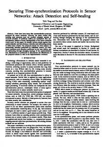
where the parameter L is equal to or multiple of PL-STF. In this paper, we have utilized L=576 since 9 short symbols of the LSTF are used, where each short symbol of the L-STF has 64 samples when the BW is set to 80 MHz. Notice that the numerator of (2) implements the autocorrelation of the received samples with the samples delayed by the L-STF length of each short L-STF symbol. The denominator of (2) estimates the received power to normalize the auto-correlation in order to diminish its dependence with the received power changes due to the multipath fading channel. The interrelations between the probability distribution function (PDF) of the estimated synchronization time and the range of discrete time transform (DFT) implemented in the receiver of a generic OFDM based PHY are depicted in Fig. 2.
Figure 2. Effects of synchronization inaccuracies in the DFT window range in OFDM based modems [13, pp. 61].
Figure 2a shows that the inaccuracies in the estimated synchronization time can cause both inter-carrier interference (ICI) and inter-symbol interference (ISI) since the DFT window range for mth OFDM symbol includes the CP of the next OFDM symbol. Although, Fig. 2b shows that both ICI and ISI can be avoided if a proper delay in the estimated synchronization time is implemented. Therefore, the synchronization time estimated using (2) is redefined as follows: + (3) ,Δ . The relation between the synchronization delay in samples Δ and the synchronization delay in seconds Δ/ is given by Δ
01 23
Δ/ ∙ 56,
(4)
where T9 is the sample interval used in the OFDM PHY. For instance, assuming the typical BW of 80 MHz used in IEEE 802.11ac/ax WLANs, then the sample period Ts is equal to 12.5 ns (1/BW) and, therefore, 20 samples correspond to a synchronization delay of 250 ns. The imperfect time synchronization introduces a phase offset when the DFT is applied to the received sequence, i.e., :;+?
@ A ∙B
CD
EF J I GH&%
@ A B CDK ,
(5)
where NDFT and Y[k] denote the DFT length and the symbol transmitted in the kth subcarrier (SC), respectively. However, if there is no ICI and ISI, as shown in Fig. 2b, then this phase offset L can be mitigated using the pilot symbols transported in the L-LTF [15]. B. Asynchronous Canonical UL MU-MIMO Channel In this paper, the asynchronous reception over UL MU-MIMO channels is modelled assuming that half of the clients have Δ