Implementation of an Image Based Focusing Algorithm for Non-Mydriatic Retinal Imaging Andrés G. Marrugo
María S. Millán and Héctor C. Abril
Facultad de Ingeniería Universidad Tecnológica de Bolívar Cartagena, Colombia
[email protected]
Departamento de Óptica y Optometría Universidad Politécnica de Cataluña Terrassa, Spain
Abstract— Retinal photography is important for the assessment of eye diseases. The task of fine focusing the image is demanding and lack of focus is often the cause of suboptimal photographs. The advent of digital cameras has provided the opportunity to automate the focusing process. In this work, we propose an auto-focus system for non-mydriatic retinal imaging. The core of the system is based on a robust image-based focus measure. The measure is basically a quantification of image anisotropy computed by means of the normalized discrete cosine transform. Additionally, we optimize the autofocusing method by evaluating different focus search strategies. Encouraging experimental results reveal that the method is able to identify the best focus reliably with optimal speed. Keywords—retinal imaging; autofocus; non-mydriatic; image processing.
I. INTRODUCTION A fundus imaging device or retinal camera is a specialized low-power microscope with an attached camera designed to photograph the retina in association with the optical system of the eye. Retinal imaging is an important tool for both detection and monitoring the progression of diseases affecting the eye [1]. Retinal cameras can be mydriatic or non-mydriatic. Mydriatic cameras require pharmacological dilation, while non-mydriatic cameras use a near infrared viewing system to exploit the patient's natural dilation in a dark room. Infrared light is used to preview the retina on a video monitor. Once the monitor's image is focused and aligned, a flash of visible light from a Xenon arc lamp is fired and the image is captured. Nonmydriatic retinal cameras are equipped with a focusing mechanism that consists in displacing a compensation lens. It is basically an aspheric objective lens design that, when combined with the optics of the eye, matches the image plane to the eye fundus. The focus control of the fundus camera is used to compensate for possible refractive errors in the subject's eye. Until recently [3], these cameras were entirely operated manually with the focusing mechanism assisted by a split line visual aid. Manual focusing is error prone especially in the presence of inexperienced photographers and may lead to images that require additional restoration or enhancement [4]. The autofocus feature offered in new retinal cameras is a significant advance that ultimately leads to a more robust imaging system, especially for medical screening purposes. On
978-1-4799-7932-5/14/$31.00 ©2014 IEEE
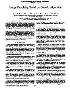
the other hand, the autofocus feature still relies on the split line mechanism, whereas in this work we propose to implement a passive auto-focus (AF) measure completely based on image analysis. For further details on fundus imaging the reader is referred to [1] and retinal image processing to [2]. This research covers the practical issues in implementing and optimizing an image-based AF algorithm for nonmydriatic retinal imaging. Each of the parameters used for focusing, such as the focus measure, the searching algorithm, or the focusing window, may be customized for optimal performance. In the following sections we present the imagebased focus measure along with several focus search algorithms. In Section 4 we discuss on the performance and practical issues in implementing the focus measure. And finally, we present the results and conclusions. II. METHODS A. Focus Measure The focus measure computes the sharpness or degree of focus on a region of an image, typically called the focusing window. The degree of focus changes as the lens is moved through different positions. Auto-focusing means automatically moving the lens such that the sharpness is maximized, i.e. the image is in the optimal focus. In [5] we proposed a new robust focus measure for non-mydriatic retinal imaging. A detailed description of the algorithm is given in [5] and is outlined below. A description of the algorithm is shown in Figure 1. The focus measure is based on the directional variance of the normalized discrete cosine transform (DCT). First, the focusing window is selected such that there are retinal structures within. Failing to provide this requirement leads to unreliable measurements. Second, the normalized DCT is computed from the focusing window. The normalized DCT is described in [5] and it guarantees invariance to contrast. The third stage consists in calculating a weighted directional sampling on the normalized DCT and finally the focus measure is the variance from all considered directions. This measure is basically an anisotropy measure with robustness given by the weighting scheme designed specifically to achieve invariance to illumination (low coefficients) and noise (high coefficients).
Fig. 1. Focus measure algorithm flowchart: A) the infra-red retinal image is acquired; B) a small focusing window is selected that includes retinal structures; C) the normalized DCT is computed; D) the DCT is sampled in predefined directions and these coefficient distributions are weighted accordingly; E) the focus measure is the variance from these directions.
asdasthe number of steps required by the search strategy. For this B. Search Algorithms study we consider the speeds of the motor and the focus The focus search strategies suggested in [6] were evaluated. measure as fixed parameters. Therefore, we evaluate the search In this section we describe the global search, Fibonacci search, strategies described in Section 3 to determine the best and hill-climbing search methods. The global search strategy performing strategy for the AF procedure. Because we are goes through every possible lens position in a unidirectional interested in determining the optimal search algorithm, we manner. The lens position with the maximum focus value is acquired images for all possible lens positions and evaluated identified as the optimal focus lens position. It guarantees to the search strategies offline. This was done by considering the find the optimal focus position, however it is the slowest following three metrics: 1) the number of AF iterations (or lens strategy because it has to calculate the focus value for all movements) required for the camera to reach the optimal focus possible lens positions. A two-step search is a fast version of position; 2) the number of motor steps the lens has traveled the global search strategy. During the first search, it performs a during the AF process; and 3) the difference (or error) between global search with a coarse step size. In the second search, the the final lens position at the end of the AF process and the real neighborhood around the optimal focus position found in the optimal focus position. From the three metrics, the first two first search is searched with a fine step size. Although it determine the speed of the AF procedure. Fewer AF iterations improves the search speed, it does not guarantee focus and fewer motor steps lead to a faster AF. Fewer motor steps accuracy. are also indication of a smaller chance of having back-andforth lens movements. As regards the last metric, a smaller The Fibonacci search strategy is based on continuously error leads to a sharper image. A good AF method should narrowing the search region by subdividing it according to the perform well against the three metrics. Fibonacci sequence. It is basically a divide and conquer process. The required number of iterations for this search is given by n = max{x : Sx < U }, where Sx is the xth number on the Fibonacci sequence and U is the number of lens positions. For 256 lens positions, the Fibonacci number just below is S13 = 233 therefore the search will require at most 13 steps to find the focused image. The Hill climbing search strategy determines the direction of the next lens movement by the gradient of the previous two consecutive focus values. The movement step is determined by a parameter L . When the direction of the lens movement is reversed, L is reduced to one half of its original value for a finer search. This can be done several times until the optimal focus position is obtained. Although the hill-climbing search strategy can start at any lens position, it it sensitive to image noise, and its performance depends on the chosen parameter values. C. Performance Issues and Experimental Details A proper AF procedure should be accurate and fast. The speed of the focusing procedure depends on the speed of the camera's focusing motor, the speed of the focus measure, and
The experimental set-up consisted mainly of an AF mechanism attached to a digital fundus camera system (TRCNW6S, Topcon, Tokyo Japan). The AF apparatus consisted of in-house assembled stepper motor mechanism for the displacement of the compensation lens controlled via RS232 with a PC. This mechanism was coupled to the fundus camera. The image acquisition and processing, along with the motor control, were carried out in MATLAB. The images were acquired from the video output of the infrared focusing system with a resolution of 640 ⇥ 480 . The focusing window was selected manually and was held fixed during the acquisition procedure. The fundus camera focusing system enables a compensation range of 13D : 12D in normal operation. For strong myopia or hyperopia two additional compensation lenses are available to compensate the ranges 12D : 33D and +9D : +40D, respectively. The image sequences analyzed here were acquired for the normal operation range. III. RESULTS In this section we show the results for the focus measure validation and the evaluated search strategies for the AF
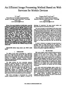
between the final lens position at the end of the AF process and the real opsition. From the three metrics, the first two determine the speed of the AF wer AF iterations and fewer motor steps lead to a faster AF. Fewer motor indication of a smaller chance of having back-and-forth lens movements. As procedure on real eye fundi. The curves shown in Figure 2 st metric,were a smaller a sharper A good AF method should computederror using aleads fixed to target located at image. infinity with respect to the fundus camera lens system. To validate the focus gainst the three metrics.
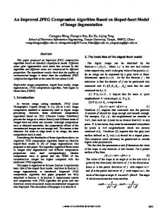
measure two lenses of +3D and 3D were placed in front of the fundus camera. This shifts the curves with respect to the mental set-up consisted mainly of an AF mechanism attached to a digital 0D curve in opposite direction. This means that the focus a system measure (TRC-NW6S, Japan). Thepower AF apparatus consisted of is able to Topcon, identify theTokyo corresponding optical compensation. In Figure 3 we show a focus curve obtained by mbled stepper motor mechanism for the displacement of the compensation focusing the right eye fundus of a 27-year-old subject for d via RS232 with a PC. This mechanism was coupled to the fundus camera. testing several focus search algorithm. The curve is monotonic quisition with andrespect processing, with the control, were carried out in to blur andalong has a unique globalmotor maximum. As described in Section 3, we tested four search algorithms. In he images were acquired from the video output of the infra-red focusing sysFigure 3(a)-(b) .we show the best performing algorithms: solution of fundus camera focusing system enables a compen640 ⇥ 480 The Fibonacci and Hill-climb, respectively. From our tests the Hill12Dmethod f 13D :climb in normal operation. strong myopia typically requires a For reduced number of AF or hyperopia two addiiterations with short motor step movements, and is accurate sation lenses are available to compensate the ranges 12D : 33D and enough for the considered application. The Fibonacci method respectively. The image sequences analyzed here were acquired for the noris sufficiently accurate but is generally slower because of long range. motor step movements.
1
0D −3D +3D
0.8
0.6
0.4 Fig. 3 Focus search algorithms: a) Fibonacci and b) Hill-climb. (Arrows) Lens movements, (red circles) lens positions.
0.2 0
10
20
30 40 lens position
50
60
Fig. 2 Focus measure validation with a test target. The red and black
REFERENCES
curves are shifted versions of the 0D curve. [1] are Bernardes, R., Serranho, P. & Lobo, C. Digital Ocular Fundus Imaging: s measure validation with a test target. The red and black curves almost equally A Review. Ophthalmologica 226, 161–181 (2011). ns of the 0D · curve, which indicates a successful identification[2]of the optical power Marrugo, A. G. & Millan, M. S. Retinal Image Analysis Oriented to the Clinical Task. Electronic Letters on Computer Vision and Image mpensation.
IV. CONCLUSION
Analysis 13, 54–55 (2014).
[3] Moscaritolo, M., Jampel, H., Knezevich, F. & Zeimer, R. An Image In this work we have presented the implementation of a Based Auto-Focusing Algorithm for Digital Fundus Photography. new image-based focus measure for non-mydriatic retinal Medical Imaging, IEEE Transactions on 28, 1703–1707 (2009). imaging. We have tested the focus measure for correct optical [4] Marrugo, A. G., Millan, M. S., Sorel, M. & Sroubek, F. Restoration of power compensation. The measure faithfully reproduces retinalthe images with space-variant blur. J. Biomed. Opt. 19, 016023 tion we show the results for the focus measure validation and evaluated defocus with the proper displacement of the curves maxima. In (2014). ies for the AF procedure on real eye fundi. The and curves in Figure 2 were addition, we tested several focus search strategies foundshown [5] Marrugo, A. G., Millan, M. S., Cristóbal, G., Gabarda, S. & Abril, H. C. Anisotropy-based thetarget Hill-climb method suitable for this with application. Not only ng a fixed located at infinity respect to isthe fundus camerarobust lensfocus measure for non-mydriatic retinal imaging. J. Biomed. Opt. 17, 076021 (2012). accurate enough, but also performs sufficiently fast, were placed idate theit focus measure twoit lenses of +3D and 3D in front of [6] Dong-Chen Tsai & Chen, H. Reciprocal Focus Profile. Image something truly required for an AF algorithm.
IEEE Transactions mera. The shifts with respect to the 0D · curve are nearlyProcessing, the same. This on 21, 459–468 (2012). he focus measure is ableACKNOWLEDGMENT to identify the optimal focus position for the correal power compensation. In Figure we show a focus This research has been partly3 funded by the Spanishcurve obtained by focus-
Ministerio de Economía y Competitividad (project DPI201343220-R). de"Óp1ca"""""""""""""""""""""""""""""""""""""""""""""""""""""""""""""""""""""""""""""""""""""""""""""""""""""""""""""""""""""""""""""""""""""""""""""""""""""""""""""""""""""""""""""""""""3