[4] Russell C. Hardie , Kenneth J. Barnard , Ernest E. Armstrong, Joint MAP registration and high-resolution image estimation using a sequence of undersampled ...
Improving SEM Image Quality Using Pixel-Super Resolution Technique Myungjun Lee*, Jason Cantone, Ji Xu, Lei Sun, Ryoung-han Kim GLOBALFOUNDRIES, 257 Fuller RD., Suite 280, Albany, NY, USA 12203 ABSTRACT The most decent scanning electron microscopy (SEM) can provide image magnification up to 500kX which seems to be suitable to image semiconductor devices for the advanced technology nodes. However, SEM images at such a high magnification often suffer from the drift and space related displacement errors, potentially causing image blur and distortion. To circumvent this, we apply the super-resolution (SR) technique to enhance the resolution of the CD-SEM metrology by using the advanced signal processing algorithms. The resolution enhancement can be realized by exploiting the multiple low resolution (LR) images that include unique information of an imaging target by looking at a slightly different position. We experimentally demonstrate image quality improvement gained by the SR technique after correcting the time-dependent drift/displacement and mapping estimated information onto the high resolution (HR) pixel grid with the non-linear pixel interpolation scheme. In addition, estimating the time-dependent drifts of the wafer position could be useful to investigate the drift properties of the CD-SEM tool. Keywords: CD-SEM, Metrology, Inspection, Interpolation, Super resolution, Shift estimation, Drift distortion
1. INTRODUCTION The semiconductor industry has been moving toward increasing the number of transistors on integrated circuits, therefore the size of structures such as fins, gates, contact holes, and etc. continues to shrink. For current advanced technology nodes, the size of several structures will be reaching to sub-10nm, resulting in the line-edge roughness (LER) and the contact-edge roughness (CER) smaller than few nanometers. For this reason, the ability to image such small structures becomes critical in both metrology and inspection. A scanning electron microscopy (SEM) is the most widely used inspection tool and the most state-of-the-art SEM tool can provide image magnification up to 500kX which translates to an effective pixel size of 0.53nm at the detection plane. In spite of such a high magnification, precise measurement of, for example, fins with 5nm critical dimension (CD) is still challenging. It is due to the fact that only 9 pixels with the maximum magnification of 500k can be utilized to measure across the fin width as well as less than 4 pixels will be available for LER and CER analysis. In addition to this limitation, current CD-SEM imaging method is often incapable of achieving the desired accuracy because the SEM images obtained with high magnification often suffer from the space- and drift-related distortions [1-3]. The drift effect is significant especially for high magnification and therefore the measured SEM images generally exhibit deformations or blur. The most direct solution to increase the spatial resolution for imaging smaller structures is to reduce the physical pixel size under the limited maximum magnification. As the pixel size decreases, however, the amount of light (i.e. reflected electrons) available for each pixel also decreases as well as the generated shot noise at each pixel degrades the image quality. At the same time, there exist technical limitations of the physical pixel size reduction. In addition, spatial aliasing together with existing noise and blurring can lead to an unreliable measurement for features described in the previously. An alternate solution is to use advanced signal processing algorithms to generate a high resolution (HR) image by using information from a sequence of low resolution (LR) images captured from the same target at slightly different locations, where these LR images represent a different “look” at the same target [4-7]. This method is known as the super-resolution (SR) technique, which has been actively investigated in a wide variety of imaging fields including (but not limited to); medical imaging, satellite imaging, video camera applications, remote sensing, and digital holographic imaging [4-9]. The main goal of our study is to improve CD-SEM image quality while minimizing the time-dependent drift distortion. The exact drift/displacement between multiple images can be estimated using both two dimensional cross-correlation Metrology, Inspection, and Process Control for Microlithography XXVIII, edited by Jason P. Cain, Martha I. Sanchez, Proc. of SPIE Vol. 9050, 90500U · © 2014 SPIE · CCC code: 0277-786X/14/$18 · doi: 10.1117/12.2046426
Proc. of SPIE Vol. 9050 90500U-1 Downloaded From: http://proceedings.spiedigitallibrary.org/ on 09/15/2015 Terms of Use: http://spiedigitallibrary.org/ss/TermsOfUse.aspx
and gradient-based shift estimation algorithms, and then the non-uniform pixel interpolation scheme is used to correct the estimated sub-pixel shifts between images. Here, we experimentally quantify the CD-SEM image quality enhancement gained by the proposed SR technique. Furthermore, this technique can provide useful information about the time-dependent drift of wafer position in the CD-SEM tool, thus it can be used to investigate drift properties of metrology tools without the need of additional instruments.
2. RESOLUTION IMPROVEMENT TECHNIQUE Currently, a variety of SR methods that enhance the resolution of an imaging system have been proposed. Some techniques termed optical or diffractive SR are being developed that the diffraction of systems is transcended, while others named geometrical or image processing SR are being developed that the resolution of digital imaging sensors and detectors is further enhanced [4-10]. The basic idea behind the principle of the image processing SR technique used in this paper will make the use of multiple LR images of the same scene in order to create a higher resolution image on the HR pixel grid [4-10]. This resolution enhancement is due to the fact that the created HR image is fusing information from all LR images those are sub-pixel shifted respect to each other by fractions of the LR grid constant. The difference among several image processing SR techniques are subject to which kind of methods are used to capture LR images, what type of reconstruction algorithm is employed, which observation model is assumed, and in which particular domain between spatial or frequency the algorithm is applied [5-10]. Figure 1 illustrates how the image processing SR method works. The physical pixel grid of imaging systems is represented in figure.1(a) and let us assume this is the low LR grid. If the multiple LR images have the different sub-pixel shifts (SPS) with respect to the first one, as shown in Fig. 1(b), each LR image can capture slightly different information of the same imaging target. Therefore, the new information contained in each LR image can be exploited to generate the HR image with the denser grid shown in figure. 1(c). In other words, for each vertical and horizontal shifts of the LR image, the output of the each physical LR pixel would be a linear combination of the high resolution pixel values (i.e. single LR pixel value would be the sum of 16 HR pixel values, as shown in the example of figure.1(c)).
Figure 1. Schematic of the super-resolution technique. (a) Discrete detector model in low resolution (LR) pixel grid. (b) Multiple sub-pixel shifted (SPS) low resolution pixel grid. (c) Example of higher resolution (HR) pixel grid.
For the better understanding of the SR technique, an observation model can be represented by the following matrix model [4,6],
y k Wk x nk for k = 1,…,p
(1)
, where yk is the matrix representing k’th LR image, Wk is the weighting coefficient matrix, and x denotes the matrix of the HR image. The noise matrix nk is assumed to be a zero-mean additive white Gaussian noise (AWGN). By assuming the HR image x has the size of LN1 × LN2, where L is an integer value, then the size of k’th LR image of yk will be N1
y
Proc. of SPIE Vol. 9050 90500U-2
Downloaded From: http://proceedings.spiedigitallibrary.org/ on 09/15/2015 Terms of Use: http://spiedigitallibrary.org/ss/TermsOfUse.aspx
× N2 with k = 1, 2, …, p. The weighting coefficient Wk includes information of blurring and sub-sampling effects, and therefore it represents the contribution of HR pixels to k’th LR pixels. This equation (1) explains that the HR image not only undergoes geometric transformation defined by the image location with respect to the reference image, but also experiences pixel blurring, spatial sampling and degradation by noise. In order to reconstruct a HR image of x from multiple sub-pixel shifted LR images of yk, following three computational steps including the shift estimation, interpolation, and restoration are required. Among these, the key to exploiting the SR technique is accurately estimating the sub-pixel shift for each frame respect to the reference image. One simple and fast method for the shift estimation is 2 dimensional cross correlation (2DCC) that measures similarity of two images, thus allows one to determine at which positions in measured two images there is a change in intensity. However, the 2DCC is only ideal when the image shift with respect to the reference image is an integer multiple of the pixel size [8]. On the other hand, the gradient based shift estimation (GBSE) algorithm is a proven method to estimate the motion shifts with sub-pixel accuracy and is important for the registration of the noisy images particularly obtained from the CD-SEM. [11]. It uses spatial and temporal filters to accurately estimate vertical and horizontal derivatives and therefore accurately estimate the image shifts [11]. In our study, we use the hybrid method by combining both 2D-cross correlation and gradient based algorithms to minimize computation time. It is important to note that the reason we rely on the shift estimation algorithm is due to the lack of precise control of a CD-SEM stage together with the existing stage drift. Once we estimate the exact information of sub-pixel shifts between images, the non-uniform interpolation scheme together with direct or iterative reconstruction procedure can create the HR image of uniformly spaced HR sampling points.
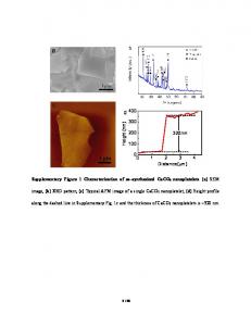
3. IMAGE DISTORTION CREATED BY A DRIFT IN CD-SEM TOOLS Accurate SEM metrology plays an important role since progress in nanotechnology has advanced rapidly by shrinking the dimensions of the semiconductor devices. However, current imaging methods using a CD-SEM suffer from the driftrelated distortion, especially with high magnifications, thus these tools are often incapable of achieving the desired accuracy because of blur and distortions in SEM images [1-3]. The following sources are known to be causing nanometer distortions or displacements on a CD-SEM tool including vibration, temperature changes, translational motion of the sample, tilt or deformation of the electron-optical column, or temperature expansion [1]. Such corruption commonly appears when conventional image-acquisition methods such as the slow scan and the fast scan are applied. The slow scan method is acquiring the image within a single scan with larger exposure time, whereas the fast scan method is generating the image composed of multiple frames with less exposure time. Due to the variation in image center position as a function of time, the phenomena described can significantly impair SEM image quality and its usability for nanometer target metrology [1-3, 7]. Cizmar et al. demonstrated image corruption caused by space and drift distortion from a slow scan image acquisition method as illustrated in figures 2 (a) and (b) for an ideal un-distorted and the typical corrupted cases, respectively [1, 2]. Figures 2 (c) and (d) show our experimental result imaging contact hole structures in a post-etch wafer and they describe how the stage drift can degrade image quality. A total of 8 CD-SEM images are sequentially collected every 15 seconds (i.e., 1 image per 15 seconds) on the fixed stage without any mechanical stage movement. One of them is shown in figure 2(c) which is a spatially discrete gray-scale image collected with 150k magnification. It has the 512×512 pixel density with the field of view (FOV) of 1µm2. The average of the collected 8 SEM images is shown in figure 2(d). In general, when the image is degraded by noise, averaging multiple images is commonly used method to increase the signal-to-noise ratio (SNR) by exchanging of one kind of information for another (i.e., extracting signal from noise) under the assumption of the target shape invariant. Unlike this expectation, what we observed from figure 2(d) is the severely distorted blurry image as a result of existing time-dependent stage drift between sequentially measured SEM images. Throughout the rest of the paper, images directly collected from the CD-SEM tool with 150k magnification will be assumed as the LR image and we will demonstrate how to create the new image with better resolution and higher SNR from the multiple LR images. Since the speed of computation is one of the critical aspects of the proposed SR technique especially in the semiconductor FAB use, we have used the hybrid shift estimation approach by sequentially using 2DCC and GBSE algorithms. First, the integer-pixel shift with respect to the first collected SEM image is calculated with the 2D crosscorrelation method, as shown in figure 3(a). The small region with the FOV ~ 150 nm × 150 nm including only 80 × 80
Proc. of SPIE Vol. 9050 90500U-3 Downloaded From: http://proceedings.spiedigitallibrary.org/ on 09/15/2015 Terms of Use: http://spiedigitallibrary.org/ss/TermsOfUse.aspx
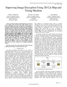
pixels is used for estimating the shifts for vertical and horizontal directions and this region should have unique features (for example, at least one contact holes in this case) for the precise shift estimation. The first collected one among 8 images is used as the reference image, where its center location is set to (0,0). Based on calculated pixel shift information, such integer shifts between images can be adjusted through the registering process. Next, the GBSE is used to figure out the sub-pixel shifts and the result is shown in figure 3(b). Figure 3(c) displays the actual displacement vector sequence, combined by both integer and sub-pixel shifts, associated with the stage drift in the SEM tool. The green line represents a linear trend of the stage drift with the slope of negative 0.75. A roughly 3 and 2.5 pixel drifts in negative horizontal and vertical directions, respectively, is observed within one minute using the magnification of 150K, which translates to approximately 5.8nm and 4.8 nm shifts, respectively, since the effective pixel size is 1.95 nm/pixel with 150K magnification in CD-SEM used for this study.
Figure 2. Illustration of SEM images corrupted by the drift-distortion. Gold-on-carbon sample: (a) Ideal undistorted image of [1,2]. (b) Typical corrupted image with slow scan image acquisition method [1, 2]. Contact holes on the wafer: (c) single SEM image with 150k magnification and (d) distorted image that is the average of 8 SEM images measured at the same location with ~15 sec time interval.
Proc. of SPIE Vol. 9050 90500U-4 Downloaded From: http://proceedings.spiedigitallibrary.org/ on 09/15/2015 Terms of Use: http://spiedigitallibrary.org/ss/TermsOfUse.aspx
.12C..11
_ __ -. __
.
__
-
ll. O. ,
-
in: ..
.
...
a
:.AI..... St image at (0,0) e::: 1
' 47.
..
e
4-0 3 -0
8St imag=
,
0
r
-0.1
----
o
- ._
0:ji:'.:iM:D .... .... ... ----
:::
- ---0:3- - --
Horizontal shift (pixel)
..
.. - :: :
---0:4-
'
-
--
-
_fl C
::.... rin:
..
Figure 3(A). Calculated integer shifts between 8 CD-SEM images using the 2D cross-correlation method. (b) Calculated sub-pixel shifts using the gradient based shift estimation algorithm after correcting integer shifts. (c) Actual drifts by adding both integer and sub-pixel shifts. Shift is estimated respect to the first collected image, where its center location is set to (0,0).
4. EXPERIMENTAL DEMONSTRATIONS In this section, we show the experimental result demonstrating the resolution improvement with the SR technique. As mentioned before, it requires the multiple sub-pixel shifted LR images those can be simply obtained through the sequential measurement without manually shifting the stage for each measurement. To quantify the performance of the SR, we first collected 8 images for an array of the contact holes in a post-etched wafer using a CD-SEM tool as shown in figure 2(c), and then successfully estimated the sub-pixel shifts between each LR image of the same target in figure 3(c). In order to make a clear comparison between LR and HR images, a digitally expanded version of them for the contact hole target are summarized in figure 4. One of LR images having the size of 200 × 200 pixels with the FOV = 0.16 µm2 is displayed in figure 4(a), and the digitally zoomed region specified with the red rectangle is shown in figure 4(d).
Proc. of SPIE Vol. 9050 90500U-5 Downloaded From: http://proceedings.spiedigitallibrary.org/ on 09/15/2015 Terms of Use: http://spiedigitallibrary.org/ss/TermsOfUse.aspx
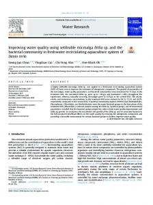
Figure 4(b) and (e) represent the average of 8 SEM images (collected at the same location) with ~ 15 seconds time interval. They experience a severe blurring as a result of the drift on the SEM stage and therefore the boundary of holes is widely spread out. Figure 4(c) shows the effectively reconstructed HR image that has 4 times larger pixel density of 800 × 800 compared to the LR image. The HR image generation is formed by averaging all processed images after correcting the time-dependent sub-pixel drifts with the non-linear pixel interpolation scheme and mapping pixel information onto the HR grid. Since all LR images are sub-pixel shifted from one another as calculated in figure 3(c), the 4× non-linear interpolation scheme can be used to produce an improved resolution image on uniformly spaced sampling points. We should note that the image pixel interpolation scheme itself is not able to recover the missing high-frequency information from the LR image, therefore the interpolation of the single image is not considered to be an SR technique. We have also looked at a different region, as shown in figure 5, to confirm image quality improvement. Once again, the visibility enhancement due to the SR is clearly observed in figure 5(c). It is evident from the generated HR images that the proposed SR technique is capable of resolving finer details due to the improved SNR and the minimized the distortion. We should note that 15 seconds time interval between each image collection is not a necessary condition for obtaining multiple sub-pixel shifted images. Under this experimental condition, 2~3 seconds of time interval would be good enough to obtain the images shifted by a sub-pixel amount because the speed of the stage drift is observed approximately 1 pixel shift per ~ 15 seconds in both horizontal and vertical directions.
Figure 4. Demonstration of the SR technique. (a) Single CD-SEM image for the array of contact holes. (b) Average of 8 SEM images without the shift correction. (c) Super resolution image with the shift correction. (d) – (e) show the expanded version of the red rectangle in figures (a)-(c), respectively.
One important assumption behind the SR technique is object invariance during multiple exposures, yielding two limitations of using the SR technique in the semiconductor industry. First, a post-etched wafer should be used in order to
Proc. of SPIE Vol. 9050 90500U-6 Downloaded From: http://proceedings.spiedigitallibrary.org/ on 09/15/2015 Terms of Use: http://spiedigitallibrary.org/ss/TermsOfUse.aspx
avoid structure shrinking due to the bleaching effect in the resist wafer. Second, such an assumption requires the LR image maintaining above a certain SNR level to avoid the substitution of one kind of uncertainty for another and the incorrect drift estimation. This paper has focused on showing the proof of concept for the image processing based SR technique on the CD-SEM tool. Further investigation will explore the optimal reconstruction methods for the practical use in advanced semiconductor nodes, primarily 7nm and 10 nm technologies. For instance, the utilization of more advanced reconstruction algorithms such as iterative back-projection, adaptive filtering, maximum a posteriori (MAP), and projection onto convex sets (POCS) would be helpful for continued image quality improvement [12, 13]. Applying additional de-convolution methods such as Winer or Richardson-Lucy filters could suppress blur and noise effects on the generated HR image. The visual quality of the estimated HR image can be further improved by increasing the number of LR images used [9]. However these advanced reconstruction approaches require more computational power, causing longer computation time.
Figure 5. Demonstration of the SR technique. (a) Single CD-SEM image. (b) Average of 8 SEM images without the shift correction. (c) Super resolution image with the shift correction. .
5. CONCLUSIONS We experimentally demonstrated a technique to improve CD-SEM image quality by applying the SR algorithm. The resolution enhancement can be realized by exploiting the multiple LR images that include unique information by looking at a slightly different position of an imaging target. Exploiting the SR technique requires accurate estimation of the subpixel shifts with fast computation, and therefore we used a hybrid approach to combine two different estimation algorithms. The HR image can be generated by correcting the time-dependent drifts and mapping estimated target information onto the HR pixel grid through a non-linear pixel interpolation scheme. We observed the visibility enhancement and resolved finer details of the sample by minimizing the drift distortion. In addition, estimating the timedependent drifts of the wafer position could be useful to investigate the drift properties of the CD-SEM tool.
REFERENCES [1] Petr Cizmar, Andras E. Vladar, and Michael T. Postek, “Real-Time Scanning Charged-Particle Microscope Image with Correction of Drift,” Microscopy and Microanalysis 17(2), pp. 302–308, (2011). [2] Petr Cizmar, Andras E. Vladar, B. Ming, and Michael. T. Postek, “Simulated SEM Images for Resolution Measurement,” Scanning 30, pp. 381–391, (2008).
Proc. of SPIE Vol. 9050 90500U-7 Downloaded From: http://proceedings.spiedigitallibrary.org/ on 09/15/2015 Terms of Use: http://spiedigitallibrary.org/ss/TermsOfUse.aspx
[3] Petr. Cizmar, Andras. E. Vladar, and Michael. T. Postek, “Advanced image composition with intra-frame drift correction,” Proc. SPIE 8036, 80360D-4, (2011) [4] Russell C. Hardie , Kenneth J. Barnard , Ernest E. Armstrong, Joint MAP registration and high-resolution image estimation using a sequence of undersampled images, IEEE Transactions on Image Processing 6 (12), 1621-1633 (1997). [5] SungCheol Park, MinKyu Park, MoonGi Kang, "Super-Resolution Image Reconstruction: A Technical Overview,” IEEE Signal Processing Magazine 30 (3), 21-36 (2003) [6] Serhan O Isikman, Alon Greenbaum, Myungjun Lee, Waheb Bishara, Onur Mudanyali, Ting-Wei Su, Aydogan Ozcan, ”Lensfree computational microscopy tools for cell and tissue imaging at the point-of-care and in lowresource settings,” Analytical Cellular Pathology 35 (4) 229-247 (2012) [7] Hengshu Liu and Xinwei Wang, ”A fast super resolution algorithm for SEM image”, Proc SPIE 6623, 66231Z (2008) [8] Premchandra M. Shankar, William C. Hasenplaugh, Rick L. Morrison, Ronald A. Stack, and Mark A. Neifeld., "Multiaperture imaging," Applied Optics, 45 (13) 2871-2883 (2006) [9] Vivek Bannore, [Iterative-Interpolation Super-Resolution Image Reconstruction], Springer (2009) [10] http://en.wikipedia.org/wiki/Super_resolution [11] Samson J. Timoner, Dennis M. Freeman “Multi-image gradient-based algorithms for motion estimation,” Optical Engineering 40(09), 2003-2016 (2001) [12] B. C. Tom and A. k. Katsaggelos, “Reconstruction of a high-resolution image by simultaneous registration, restoration, and interpolation of low-resolution images,” proc 1995 IEEE Int. Conf. Image processing 2, 539-542 (1995) [13] H. Stark and P. Oskoui, “ High resolution image recovery from image-plane arrays, using conver projections,” J. Opt. Soc. Am. A 6, 1715-1726 (1989)
Proc. of SPIE Vol. 9050 90500U-8 Downloaded From: http://proceedings.spiedigitallibrary.org/ on 09/15/2015 Terms of Use: http://spiedigitallibrary.org/ss/TermsOfUse.aspx