Bruce H. Thomas, G Stewart Von Itzstein,. Rudi Vernik, Shane Porter, Michael R. Marner,. Ross T. Smith, Markus Broecker and Ben Close. School of Computer ...
14 Apr 2011 - Makalah ini membahas pengembangan realitas tertambah (AR) ... untuk peningkatan informasi komputasi untuk setiap atribut data dan ..... This work is jointly supported by the UTMVicubeLab, FSKSM, Universiti Teknologi.
certain hobbies (videogames, walking, crafts, illustration/photography and travelling). ... Graphic Design Degree (from now on MGD) and 35 Videogames Design ...
Mehrasa Alizadeh, Osaka University, Japan. Erin Noxon, Sagano Gakuen, Japan. Asian Conference on Technology in the Classroom (ACTC). Kobe, May 2017 ...
An interior design application is used as an example to demonstrate the advantages of our .... In general, it can be a challenging task for the interface builder to.
the workspace of an industrial CNC (computer numerical control) machine. .... the power of the machine, such that the lifetime of the tool can be maximized and tool .... The interpreter would be relevant also for training purposes, allowing ...
results of spatial ability tests in high schools are presented. ... reality, computer supported collaborative work. ...... [25] C. A. Lawton, "Gender differences in way-.
May 17, 2018 - extending the current operational envelope while enhancing flight safety. Several flight ..... In cockpit applications, with helmet or head-mounted.
... of the Manipal Technologies Ltd, is a content service company that provides end-to-end services across the content v
... in terms of pre-media solutions, web and app development, gaming, anima- .... At Manipal Digital, we work with some
ated an early prototype of a mobile AR system (MARS) that registers 3D .... Limited. Limited. Power economy. +. â .... be prepared with a local base station that sends a differential ..... vironmental Detectives' where each educative game has an.
visualization of the 3D data and not on 3D data manipulation techniques. ..... reality software and technology, Baniff, Alberta, Canada, 2001. [13] J. Kehrer and H.
a Departments of Information and Computer Sciences b Department of Neurology, University of California, Irvine. Abstract. This paper ... motor function, in the following, we discuss the state-of-the-art research that has been ..... S. Dai, E. S. Ford
Augmented reality application assistant for spatial ability training. ... Development of spatial skills on the part of engineering students is .... Engineering Design.
Feb 8, 2018 - Then, one learns an individual SVM on each cell by solving for a regularization parameter λ > 0 the opti- mization problem. fDj ,λ = arg min fâHj.
Dec 1, 2014 - aspects of mathematics, especially with number writing and magnitude judgment. [2]. .... 10 third-year medical students participated in the study. .... designed 28 image targets by using Adobe Illustrator, and then, we rotated .... had
Abstract. This paper features a Spatial Augmented Reality system for rehabilitation of hand and arm movement. The table-top home-based system tracks.
ABSTRACT: This paper presents a new methodology for utilizing Augmented Reality (AR) fiducial markers on mobile devices (smart phone/tablet) for indoor ...
Dec 1, 2016 - circumvent this barrier (cf. [2] for an overview): Sequential Minimal Optimization [12] allows for caching. 1. arXiv:1612.00374v1 [stat.ML] 1 Dec ...
Apr 14, 2011 ... visualisasi yang mendukung identifikasi, lokalisasi, dan visualisasi ... menjadikan
proses eksplorasi dan visualisasi data sangat rumit dan ..... Input from the
sensors are normalised into a native Microsoft Excel format with each.
our interest. Thuse we do hope that someday AR will be integral part of our everyday life. 3. .... in CAD design. Maybe someday it will become an integral part of ...
alert to cognitive demands as they design or fund their AR .... digital gaming environment, the web page, the video stream, .... hire/train those who know about.
customized appearances using only projected light. Finally, we also discuss design parameters of building dedicated projection environments including room ...
Chapter 10
Large Scale Spatial Augmented Reality for Design and Prototyping Michael R. Marner, Ross T. Smith, Shane R. Porter, Markus M. Broecker, Benjamin Close, and Bruce H. Thomas
Abstract Spatial Augmented Reality allows the appearance of physical objects to be transformed using projected light. Computer controlled light projection systems have become readily available and cost effective for both commercial and personal use. This chapter explores how large Spatial Augmented Reality systems can be applied to enhanced design mock-ups. Unlike traditional appearance altering techniques such as paints and inks, computer controlled projected light can change the color of a prototype at the touch of a button allowing many different appearances to be evaluated. We present the customized physical-virtual tools we have developed such as our hand held virtual spray painting tool that allows designers to create many customized appearances using only projected light. Finally, we also discuss design parameters of building dedicated projection environments including room layout, hardware selection and interaction considerations.
1 Introduction Spatial Augmented Reality (SAR) projects perspectively correct computer generated images onto physical objects to enhance their appearance and functionality. Most forms of physical matter can have their appearance altered using projected light, allowing familiar looking objects to be instantly transformed to take on a completely new facade. Our research focuses on how this innovative technology can be applied to support industrial designers during prototype development by enhancing the tools available for mock-up creation. We envisage that SAR will revolutionize the industrial design process with two significant features that are not available using traditional mock-up creation techniques. Firstly SAR provides
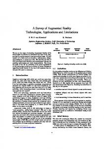
Fig. 10.1 Example of a SAR mock-up stages. (a) Simple mock-up prepared for SAR visualization. (b) Handwritten annotations projected onto mock-up. (c) Enhanced mock-up using SAR to provide appearance and functionality information
a rich fully featured appearance that can be instantly altered at the touch of a button. For example, the layout of a car dashboard can be instantly altered from right to left hand drive without any physical change to the mock-up. Secondly, full functionality of simulated controls, such as a climate control system, can be implemented without the need for physical buttons, lights, displays or electronics to be installed in the prototype. Instead the SAR technology can provide all the functionality using projected light, a tracking system, and customized software. An example of SAR technology in use is shown in Fig. 10.1. Figure 10.1a depicts a SAR prototype mock-up of a car dashboard using cheap, light weight materials for its construction. Figure 10.1b shows the same mock-up with simple annotations and Fig. 10.1c demonstrates a fully featured appearance that leverages SAR technology for its functionality and design visualization. In 1965 Ivan Sutherland stated that “The ultimate display would, of course, be a room within which the computer can control the existence of matter. A chair displayed in such a room would be good enough to sit in. Handcuffs displayed in such a room would be confining, and a bullet displayed in such a room would be fatal” [31]. While SAR cannot control the existence of matter, we believe the technology is the next step bringing us closer to making his vision a reality. In this chapter we discuss how the powerful new SAR technology can be applied to support industrial designers by expanding the current design methodology. The chapter begins by defining SAR and explains the differences between common display technologies used for Augmented Reality. Following this, a background presenting the state of the art of SAR systems, applications and the industrial design process is summarized in Sect. 2. A discussion on enhancing the current industrial design methodology by leveraging the features of the SAR technology is presented in Sect. 3. Section 4 demonstrates practical applications, we discuss five case studies that are made possible using a SAR environment. Current tools and applications are discussed in Sect. 5. Design considerations when constructing SAR environments are discussed in Sect. 6. Finally, we conclude with a discussion on future directions of SAR technology in Sect. 7.
10 Large Scale Spatial Augmented Reality for Design and Prototyping
233
1.1 Spatial Augmented Reality Spatial augmented reality enhances the physical world with computer generated graphics from digital projectors [21]. This is in contrast to other Augmented Reality (AR) display technologies, such as Head Mounted Displays (HMD) which place augmentations on an image plane in front of the user’s eyes, and hand-held devices which show augmentations on a hand-held display. SAR requires physical surfaces to project onto. These surfaces can consist of any objects in the environment that are of interest to the user; projections are not limited to walls or purpose built screens. Unlike CAD and other AR display technologies, SAR allows users to physically touch the virtual information. The surfaces provide passive haptic feedback and all stereoscopic depth cues are naturally provided. Previous virtual reality research has shown that the ability to touch virtual objects and information enhances user experience [9], and can improve users’ performance [36]. This physical nature of SAR makes it a compelling choice for industrial design applications since the designers can physically touch the mock-up prototypes and leverage the flexible computer controlled appearance. Hare et al. [8] describe the importance of physical prototypes in the design process. Using SAR, designers can naturally interact with design mock-ups, without having to hold or wear display equipment. As SAR places computer generated information directly onto objects in the real world, groups can view and interact with the system. This makes SAR an ideal choice for collaborative tasks. SAR also has similarities to the Cave Automatic Virtual Environment (CAVE) [6]. CAVEs are immersive virtual reality environments where perspectively correct graphics are projected onto the walls, floor, and sometimes the ceiling of a four sided room. The user stands in this room and experiences a virtual environment that appears correct from their point of view in the room. CAVEs use the same display equipment and techniques as SAR: calibrated digital projectors. However, for the most part, this is where the similarities end. SAR projections fall onto the physical objects of interest, such as design artifacts. The projection screens of a CAVE are planar surfaces on which to view the virtual images, acting as windows into a virtual world. This virtual window metaphor also affects the types of interaction possible in a CAVE. Interaction is inherently action-at-a-distance, since the objects of interest exist only in the virtual world beyond the projection screens. Physical handles and props can be used to aid interaction, but there is still some disconnection between actions a user performs and the virtual result of these actions. SAR applications are usually interested in the physical objects being projected onto. Therefore, interaction can be much more direct; the user can easily move whole objects around by hand, or manipulate the projections using their hands or physical tools. CAVEs must project view dependent graphics for the system to function. This requirement limits the number of users able to use a CAVE simultaneously, although some systems time-multiplex multiple views by dividing the frames from the projector and using active shutter glasses to ensure each user only sees their correct view. HMD and handheld based AR applications usually also require view-dependent
234
M.R. Marner et al.
graphics. In contrast, SAR must project scene dependent graphics to function. A SAR system works independently from the users, making collaboration with large groups more easily achievable. View dependent projections are only required when view specific effects are desired, such as specular highlights, accurate reflections, and transparency.
2 Background In this section we give an overview of related spatial augmented reality research, applications of SAR technology, and the industrial design process. Spatial augmented reality builds on research into digital workspaces, such as Augmented Surfaces [26], which provides a work environment where information is shared between computers, projection screens, and augmentations on desks. This idea is further explored in the Office of the Future [23], which proposes using computer vision techniques to create a model of an entire office, and then using the entire office for augmentations. Our focus on industrial design applications is inspired by Shader Lamps [24], which uses calibrated projectors to change the appearance of an object. This calibration requires finding the intrinsic parameters of the projector (focal length, field of view, etc.), and its position and orientation relative to objects of interest. This calibration can be automated through the use of structured light [11]. Given a textured 3D virtual model of an object, different materials and lighting conditions can be simulated. In addition, non-photorealistic shading models can be used, to provide effects such as cell-shading on objects in the real world [25]. Shader Lamps has also been extended, allowing users to digitally paint onto movable objects [2], and similar technology has been used to superimpose computer graphics on top of visual art pieces [3]. Shader Lamps style systems project directly onto objects in the environment, extending the size of the augmented environment requires adding more projectors. An alternative to this approach is the Everywhere Displays Projector [16], which uses a rapidly rotating mirror in front of the projector, to redirect projections to anywhere in the room. The main downside to this approach is the projector must be “shared” between areas receiving augmentations, limiting the number of areas that can receive augmentations simultaneously. Another type of SAR display is the Virtual Showcase [5]. Here, objects of interest are placed inside a case of half silvered mirrors. Projectors shine onto the surface of these mirrors, and give the appearance of information being projected onto and around the object. The main downside to the Virtual Showcase is that as objects are inside a case, it is not possible to directly touch and interact with them. This type of display is most suited to museum displays and other situations where the object should not be touched. SAR user interfaces have similarities to tangible and graspable user interfaces (TUI) [7], where physical objects act as handles to elements of the user interface. Ullmer and Ishii describe how physical counterparts to common user interface controls can be created [33]. Projector based TUI applications have been used for
10 Large Scale Spatial Augmented Reality for Design and Prototyping
235
tasks such as landscape analysis [18] and urban planning [34]. The physical nature of SAR makes TUI type user interfaces a compelling choice. Users can interact with the system in the same way they can physically touch and move objects around in the environment.
2.1 SAR Applications There are several types of applications where SAR has been used in an industrial context. These include training, maintenance, on the job assistance, and design. Providing training through SAR involves projecting instructions for the user to follow. An example of this is the billiard instruction system [30] which instructs the user on how to play billiards by projecting images onto the playing surface. CADcast [17] projects assembly instructions onto a workbench, instructing the user on how to assemble a complex object. SAR can also be used for providing assistance to a user while they are performing a task. Using SAR for assistance may reduce the completion time or amount of errors for the task. An example of this is RFIG Lamps [20] which use handheld mobile projectors to identify important objects that have been marked with radio frequency tags. This technology could be used to identify certain packages from a pile, which would save searching time for a worker in the package delivery business. Using SAR for maintenance involves projecting onto parts of a complex object that need to be checked or maintained by a user. The requirement for this application is that the projections are correctly registered with the corresponding part of the object. Laser projectors have been used to project onto welding points of a car door [28]. These projections highlight the parts of the car that need to be inspected by the workers. Laser projectors have also been used for programming the motion paths for industrial robots [37]. A tracked stylus is used to draw the motion paths, which are displayed using the projector. An additional use of SAR in the workplace is for design. The design for an object can be projected directly onto a physical prototype [1]. The projected images displayed on the prototype are changed in real-time to display different designs. WARP [35] allows designers to preview material properties for cars, by projecting onto 3D printed models. A standard desktop user interface is used to select materials and other visual features.
2.2 Industrial Design Process and Concept Mock-ups Designers select a design methodology according to the requirements of the task at hand. Pugh’s Total Design Model [19] and Pahl and Beitz’s model of design [15] are two examples of commonly applied methodologies. Whichever design methodology is chosen, concepts need to be generated that provide solutions to the
236
M.R. Marner et al.
design specification. This phase of design is called the concept stage. The typical process during the concept stage is to: (1) generate ideas, (2) create concepts that embody the ideas, (3) evaluate the concepts, and (4) select the most promising concepts. Using CAD and other design applications to express conceptual ideas is common place. Creating physical mock-ups to assess the viability of a concept is also common during the industrial design process. In practice, a combination of materials is needed to create mock-ups with diverse features. The designer explores different materials, colors, textures and dimensions repeatedly to find the best way to visualize a concept.
3 Industrial Design Process Using SAR One of our goals is to explore how phases of the modeling methodology used by industrial designers can be enriched by using SAR technologies. The purpose is to allow designers to visualize their concepts with higher detail and be provided with a more flexible modeling environment. The existing industrial design concept phase modeling process is depicted in Fig. 10.2a. This demonstrates how designers are required to rebuild and often restart their prototype designs during the concept development. For example, consider a mock-up of a car dashboard where the
Fig. 10.2 Concept modeling process: (a) traditional mock-up flow (b) updated mock-up flow using SAR for modeling
10 Large Scale Spatial Augmented Reality for Design and Prototyping
237
designer has constructed a basic right hand drive design. Assume the requirements suddenly change and a left hand drive car is required. This is a significant design change that requires a fundamental feature of the design to be re-developed. Significant changes to the initial mock-up or a new mock-up must be built. In comparison, when using SAR for development the goal is to allow both the physical model and appearance to be easily altered without requiring a new prototype to be constructed. The basic mock-ups used for projection are very simple and lightweight. Only a simple approximation of the final shape is required to allow the visualization of initial prototypes. The appearance of the mock-up is transformed to present all the fine grained details of the design. This can then be easily changed to move the location of significant features, such as a steering wheel, or change the entire surface color at the touch of a button. This functionality of SAR allows the design methodology shown in Fig. 10.2b to often remove the need to re-construct a prototype mock-up. We are primarily focused on two aspects of the concept visualization process: the procedures used to augment the visual appearance of the mock-up, and the techniques and materials used to create the physical prototypes.
3.1 Visualizing a Mock-up The surface appearance is an important aspect of the physical mock-up. Designers use paint and inks to color and annotate their mock-ups. A disadvantage with this approach is when changing a design, either a separate mock-up needs to be constructed or the initial mock-up must be re-painted. Although clay and polymer plasticine are able to have their shape changed continuously, this is not possible once painted, as the painted surfaces become less malleable. We consider these to be limitations of the current practices of mock-up creation in the industrial design process. An alternate approach we are investigating is to use SAR with Physical-Virtual Tools (PVT) to alter the surface appearance by projecting virtual textures directly onto a physical mock-up [12, 14]. This technology overcomes the second limitation by allowing multiple appearances to be projected in succession onto one mock-up. The designer may digitally paint directly onto the model by interactively modifying the projected texture to alter the appearance. The texture can be saved and recalled later for further evaluation (see Sect. 5.1 for a detailed description). Although features in the concept stage are created, the actual dimensions are often not well defined. Finding the correct dimensions, shape, and appearance to visualize a concept is therefore an iterative process, moving back and forth between visualizations until the result is satisfactory. A material that facilitates this process is considered a requirement. As previously mentioned, traditional mock-up materials and techniques require a new mock-up to be built after the shape is significantly changed or the visual appearance is changed, adding to the total time and material involved in the concept stage.
238
M.R. Marner et al.
SAR can also leverage any preliminary concept sketches, textures and design ideas that are created in the early concept stage. SAR provides the ability not only to generate a new appearance, but also present the initial ideas by projecting them directly onto the physical models. This functionality is inherently provided by the SAR system and intended to maximize the visual information and presentation to the designer.
3.2 Current Mock-up Materials Industrial designers can utilize several techniques for constructing a physical mockup and visualizing a concept. In this section we examine three major materials and techniques: rigid materials, 3D printing, and malleable materials. With the exception of very high end color enabled 3D printers, these techniques are used to construct the physical mock-up only, and do not focus on the appearance. Mock-ups need to be painted to provide a finely detailed surface appearance. Rigid materials such as urethane foam, cardboard, timber, and plastics allow for the quick creation of mock-ups. The level of detail is limited by the skill of the designer and the time spent on the creation of the mock-up. Although the level of detail of the mock-up may be quite high, the shape of the models is difficult to change once created. 3D printing technology is now available to industrial designers for use in mock-up construction. The mock-up design is expressed using CAD software. The design is then printed to create a physical object. 3D printers are a very powerful tool for creating high fidelity mock-ups, however there are a number of limitations. The rigid nature of the material limits physical reworking. Reprinting designs in order to correct mistakes is a common occurrence. Currently, a second limitation is the long printing time, which requires hours before the design can be assessed and further reworked. Finally, CAD modeling is typically limited to keyboard and mouse interaction. The designer is unable to feel the properties of the material during development. With the absence of tactile feedback, designers create their digital models based only on their familiarity with the physical materials. In particular modeling of organic shapes without tactile feedback is difficult, especially early in the product development cycle. Malleable materials such as clay and polymer plasticine are well suited for the creation of organic shapes by employing free-form modeling techniques. Designers manipulate these materials with their fingers to form the mock-up. The flexibility of the material allows the designer to change the shape of the model after its initial creation. Clay and polymer plasticine overcome the problems of remodeling a design. A drawback to using clay or polymer plasticine is that it is impossible to change the shape after colors have been applied. In addition, clay and polymer plasticine both suffer from a lack of structural strength, limiting their ability to
10 Large Scale Spatial Augmented Reality for Design and Prototyping
239
create large flat suspended sheets or large hollow objects. Large clay models are particularly heavy and not appropriate for many prototype mock-ups. To overcome this, a common practice is to use them in conjunction with cardboard or timber to create the underlying structure which the clay or polymer plasticine is applied. However, combining materials further limits the extent to which the shape can be changed afterwards making it difficult to iterate the design without constructing a new model. Combining materials may also cause problems with producing a finish on the prototype that is consistent across the different materials that are used.
4 Practical Considerations for SAR Visualizations SAR systems can be built to support augmentations onto objects ranging from small hand-held objects through to room, building, and Olympic swimming pool sized objects. There are several issues in implementing SAR systems. Some of these apply to any SAR system, where others depend on the scale of objects being projected onto. This section provides insights into the implementation and operational aspects of SAR systems at varying scales. We discuss technical and theoretical aspects such as the number of projectors required for each case and special requirements for software, hardware, and interaction techniques.
4.1 Tracking With the exception of extremely large objects, tracking the position and orientation of objects and users in the environment is an important aspect of interactive SAR applications. Tracking objects allows their projections to be updated as users interact with them, and also the user allows view-dependent rendering effects to be implemented. Tracking real-world objects is an active area of AR research. Many factors, such as jitter are important considerations in all applications tracking real world objects. A thorough review of tracking techniques is beyond the scope of this chapter. However, there are several constraints and issues that are unique to tracking in SAR systems. Latency, the time difference between when a user moves an object and the system registering this change, can be a major problem with tracking systems used with SAR. AR and VR researchers have always had to deal with this problem, which manifests itself in HMD based systems as virtual information appearing to “float” around the physical objects it is registered to. However, this problem is exacerbated in SAR applications, as the virtual information is projected directly onto the surface of the physical objects. High latency will cause projections to appear in the wrong location, or spill onto other objects in the environment. Another problem unique to SAR involves computer vision based tracking solutions. Many off-the-shelf tracking libraries use fiducial markers, which are detected in camera images in order to obtain the location of objects [10]. The
240
M.R. Marner et al.
cameras tracking these fiducial markers usually require good, predictable ambient light. However, SAR projections appear better with low ambient light. In addition, SAR projections change the appearance of the fiducial markers themselves. The combination of these two factors make fiducial marker tracking difficult in SAR environments. Ideally, tracking systems employed by SAR systems should avoid markers in the visible spectrum. Alternatives include magnetic tracking, such as systems from Polhemus,1 or marker based tracking that operates in the infra-red spectrum, such as commercial systems provided by Optitrack2 and other manufacturers. If visible-spectrum based tracking is to be used in a SAR system, much higher performance can be obtained by using active markers, such as LEDs [29].
4.2 Projector Placement The relationship between projectors and objects greatly affects the visual quality of the augmentations. For smaller systems, a single projector can be used. However, this limits the number of viewpoints that can view augmentations. Larger systems might allow users to walk around a large object, such as a car. Here, multiple projectors will be needed to project onto all the surfaces of the object. Multiple projectors are also required to compensate for self-shadowing that occurs with complex objects. However, using multiple projectors introduces the problem of projection overlapping. Multiple projections may overlap on the model’s surface creating a non-uniformly bright surface. Algorithms for blending overlapping projector volumes have been developed for static scenes [22], but remains an open research problem when objects can be moved, as the blending must be recalculated every frame. Projector placement is a trade-off between a larger distance from objects (and therefore a larger projection volume), and higher spatial resolution. By increasing the distance between projector and projected area, the size of projector pixels grow, while the light intensity declines. In addition, the incident angle of the projected light changes the physical shape of the pixels. If a projector illuminates a surface at an oblique angle, a large area on the physical object will be mapped to only a few projector pixels, severely reducing the visual quality. While the texture resolution of the model can be increased, the final output is limited by the projector resolution. This is an important consideration for hand-held objects, where the projection area available is already very small. Short throw projectors can alleviate this problem, providing a suitable sized projection volume, with the projector-object distance minimized, meaning projections appear bright. If multiple projectors are used, different projectors will create differently sized and shaped pixels on the surface of the object.
10 Large Scale Spatial Augmented Reality for Design and Prototyping
241
When projecting onto three dimensional objects or a flat surface at an angle, there is no clear focal distance. Therefore, some parts of the augmentations will appear sharp, and others will be out of focus.3 In practice, a focal distance should be chosen to maximize the area on the object with adequate focus. An alternative is to use several projectors at the same location, but focused at different distances. The rendering system can then choose the best projector for each part of the object [4]. Projector focus is most pronounced when projecting onto large objects, such as a car, or in a large, walk-around environment.
4.3 Interaction The choice of interaction techniques is a critical design decision for SAR applications. While interaction with desktop software is almost universally accomplished through keyboard and mouse, these are usually not the best choice for SAR applications. The types of interaction techniques possible in a SAR system will depend on the scale of objects projected onto. For smaller table-top systems, direction interaction is most suitable, as the augmented objects are also small, and can be picked up and moved directly by the suer. Passive haptic feedback is a fundamental benefit of SAR systems and small scale SAR systems are ideally suited to interaction involving physical tools and interaction with objects using the hands. The table itself is also a projection area, where information, menus, and other user interface elements can be presented in a non-intrusive way. As the scale of objects increases, users are no longer able to manually move them. The interaction will therefore focus on the details projected onto the object. For medium sized objects, such as a fridge mock-up or a car prototype, the interaction will focus on the augmentations on the object. For these objects, a combination of direct interaction on the object, and action at a distance techniques will be required. Physical tools could be used to support this. For very large objects, such as the side of a building, the interaction will become more focused on action-at-a-distance, as the user must stand back from the object in order to view and understand the projected information. Here, techniques such as laser pointer interaction may be useful.
5 Tools and Applications In this section we describe some of the tools and applications we have developed as part of our investigations into using SAR in the design process.
3 This
only applies to LCD or similar projectors that use a lens, but not LASER-based projectors as they do not have a focal distance.
242
M.R. Marner et al.
Fig. 10.3 Digital airbrushing with SAR. (a) The airbrush tool. (b) Using a virtual stencil to paint a model car. (c) Airbrushing result
5.1 Airbrushing Digital airbrushing [14] allows a designer to virtually spray paint onto a physical object. The application allows designers to experiment with different finishes for a design mock-up, and shows how SAR can be used in the design process to preview finished products. Digital airbrushing shows how industrial design applications can construct their user interfaces from Physical-Virtual Tools (PVT) [13]. PVT are physical tools the designer works with to interact with the system. The physical nature of these tools means they can be projected onto like any other object in the system. By changing the projections on the tool, a tool can be meaningfully overloaded with several functions. Three tools are used in this application: the airbrush, the stencil, and the stylus. Airbrushing, shown in Fig. 10.3, works in a similar way to a real airbrush. The amount of paint hitting the surface depends on both the distance and angle between the airbrush tool and the surface of the object. Adding the stencil tool allows a designer to mask out areas from receiving paint. The stencil is a physical board, but the mask shape is digital and projected onto the tool. Designers can select from a library of premade stencil shapes, or draw their own directly onto the board. The stencil also functions as a Personal Interaction Panel [32] for command entry. The stencil shows the benefit of PVT. The physical nature of the tools provide passive haptic feedback against the design artifacts and when drawing the stencil. Rather than using many different stencil tools for each shape, only a single tool is needed. Designers can draw their own stencil for specific needs. The stencil itself can be virtually inverted, either acting as a mask, or as a hole that allows paint to pass through. This functionality could not be replicated easily without PVT. A 3D virtual model that matches the physical object is required for painting onto movable objects. However, simple stand-in geometry can be used when no virtual model exists, such as early in the design process. In this scenario, a bounding box is used for the virtual geometry. The nature of the projection means that the paint will appear in the correct location on the object, as depicted in Fig. 10.4.
10 Large Scale Spatial Augmented Reality for Design and Prototyping
243
Fig. 10.4 Left: The virtual bounding box, drawn from the point of view of the projector. The location of the physical mock-up is shown inside the bounding box. Right: The projected textures map correctly onto the physical mock-up
5.2 Augmented Foam Sculpting The examples we have described so far require 3D virtual models for objects being projected onto. However, such models do not exist early in the design process, as design concepts and forms are still being developed. Augmented foam sculpting [12] bridges the gap between physically sculpting a design mock-up and creating a virtual model in CAD software. A hand-held, hot wire foam cutter is used to carve a block of foam stock into the desired shape. The foam and cutter are both tracked, allowing the system to record the motion of the hot wire through the foam. Recording the motion of the wire enables the system to replicate the cuts to create a 3D virtual model that matches the physical foam. This eases the transition into the CAD phase of design, since the mock-ups created early on are available for editing digitally. Most importantly, the system fits in with existing industrial design processes, and uses skills designers already have. Foam mock-up creation is already a common part of the design process. Virtual foam sculpting is implemented internally as a series of constructive solid geometry boolean operations. As each cut is made, representative geometry is constructed, and this is subtracted from a virtual foam blank. This process is illustrated in Fig. 10.5. The functionality of the system is greatly enhanced through the use of SAR. Since the position and orientation of the foam is tracked and its geometry updated in real time as it is sculpted, perspective correct graphics can be projected onto it. Our initial investigations have used SAR for material previews, and two visualizations for helping designers: cut animation and target.
244
M.R. Marner et al.
Fig. 10.5 The path the cutter takes through the foam is recorded, geometry is created, and a CSG boolean difference operation is performed
Different material properties are simulated on the foam through the use of 3D textures. 3D textures are ideal for this process as it eliminates the need for a 2D texture atlas, which is important given the geometry is constantly changing. The material appearance also remains consistent as cuts are made onto the foam. We have implemented a procedural 3D wood grain texture using a modified version of the algorithm presented by Rost [27]. Any material that can be represented as a 3D texture be projected onto the foam using this technique. We have also projected the wireframe generated from sculpting onto the foam for verification purposes. Cut Path (Fig. 10.6) allows designers to recreate a previously sculpted model. The visualization sequentially projects each cut necessary to create a mock-up onto the blank foam. This could be used for instructional purposes. In addition, industrial designers often use foam mock-ups as an inexpensive alternative to 3D printing. A lot of time is invested in deciding on the cuts needed to replicate a model. An algorithm could be developed to calculate the cuts needed to produce a CAD model using this visualization. Target Visualization (Fig. 10.7) shows the designer which areas of foam need to be removed to produce a target model. This is an alternative to Cut Animation. Here we do not display step-by-step instructions. Instead, the surface of the foam is color coded depending on the amount to be removed form the area. Red indicates a large section of foam should be removed, transitioning to green when the target depth has been reached.
5.3 Virtual Control Panel Design We envision SAR as being a useful tool for the design of control panels. By projecting components onto a physical mock-up of the control panel, it removes the need to install custom electronics to obtain a functioning control panel. Possible projected
10 Large Scale Spatial Augmented Reality for Design and Prototyping
245
Fig. 10.6 Cut Path projects the cuts to be made onto the foam
Fig. 10.7 Target Visualization colors the foam based on how much should be removed to produce a target model
components could include buttons, dials, or even simulated displays. Using SAR to assist with this step in the design process can save time and money for designers. Components that would normally be installed as physical components on a prototype can just be projected onto the prototype. This saves time since the components do not need to be installed. To project a component using SAR, all
246
M.R. Marner et al.
Fig. 10.8 A designer interactively modifies the position of projected buttons on a control panel prototype
that is needed is a 3D model of the component and a texture to apply to that 3D model. When these are projected, it gives the appearance that the component has been placed on the surface of the prototype. Since the projection is generated by a computer, it can be changed in real time. For example, the position of the projected component is not fixed and can be moved to a different position. Also, functionality could be added to the projected components, such as buttons being illuminated. This functionality is programmed into the SAR system and allows designers to define what the different components do when users interact with them. There are several controls that are ideal for designers to use when creating a virtual control panel. Basic manipulation operations such as moving, scaling and rotating the virtual components are very useful for designers that want to change the layout of a control panel. Additional features such as copying, cutting and pasting components could also reduce the time it takes to design the control panel. Lastly, another important feature is being able to take a snapshot of the current design and compare it with other snapshots. This gives the designer a method of quickly comparing two different control panel designs. Figure 10.8 shows a user interactively moving the position of projected buttons on a control panel prototype. This tool for creating virtual control panels is designed to be used early in the design process, where the specific positions of components is not finalized. To understand the basic layout of the components, they can be projected onto a lowfidelity model of the control panel. This low-fidelity model can be made out of wood, foam or even cardboard. The components can still be projected onto these surfaces, but if the physical shape of the control panel needs to be changed, then the materials are cheap to replace. This encourages designers to find an optimal physical
10 Large Scale Spatial Augmented Reality for Design and Prototyping
247
model for the control panel, since it is quicker and cheaper to replace a low-fidelity prototype than a fully functional prototype where additional time is spent installing the electronic components. There are two options for projecting components onto a control panel. Firstly, the component can just be projected directly onto the surface of the prototype and appear as a 2D representation of the component. The other option is to create a movable physical model of the component so that it appears in 3D to the user. One difference between these two methods is that the physical model of the component will provide natural haptic feedback to the user, whereas a 2D projection on a surface will not. This can change how some components are controlled, since a projected 2D dial can not be turned like a regular physical dial.
5.4 Control Room Layout One application of SAR is designing the layout of a room. If each component of the room is tracked, then the projected design for each component can be updated to appear on any moving objects. This allows users to dynamically change the arrangement of several tracked objects. An example application of this is for the design of a control room such as in a submarine or a ship. These rooms contain several work stations that are used to control various parts of the vessel. In the design of these rooms, an optimal layout for the work stations needs to be decided. Using SAR, we can project onto movable work stations that can be reconfigured into the desired layout (Fig. 10.9). This has similar benefits to virtual control panel design such as saving time and money during the design process. The advantage of this approach is that the physical models can be moved into a custom configuration during the design of the room. Another example application is designing the layout of a kitchen. Physical models of the appliances could be moved into a desired kitchen layout, with the designs for those appliances projected directly onto the models. The material used for each appliance could be changed, so that the user can see what the kitchen will look like with different textured finishes such as wood or metallic.
6 Requirements for a Large Scale SAR Environment A calibrated projector and computer system are the minimum hardware requirements for a SAR environment. However, to provide a more feature rich environment, additional projectors can be added to increase the volume of augmented space. In addition, object tracking can be used to increase immersive interactions, and customized hardware can be created to support interactions. A large scale SAR environment places further requirements on computer system management, cabling and signal routing, networking, as well as environmental considerations such as air conditioning, projector mounting systems, and lighting.
248
M.R. Marner et al.
Fig. 10.9 The SAR system simulating a controlroom, composed of three individual control panels. The user is able to modify the individual instruments on each of the control panels, as well as reposition the panels themselves
This section describes requirements we have found for the development of large scale SAR systems. We base these requirements on lessons learned from building our own forty-projector SAR environment in the Mawson Institute at the University of South Australia. This laboratory is used for investigating how SAR technologies can be leveraged to enhance design aspects of automotive, white goods, free-form modeling, and training devices. Supporting these varied applications has led us to develop a large scale SAR environment that can be easily re-configured.
6.1 Physical Environment The physical environment determines how many SAR applications can be supported simultaneously, how easily new applications can be deployed, and the maximum possible size available in the environment. Although it is possible to set up a SAR environment in non-dedicated rooms for small applications, we are interested in applications that allow large artifacts to fit in the environment and benefit from the technology. The size, layout and access to the physical environment are important aspects. The size of the environment should be large enough to cater for the largest object to be used. Additional space is required around projected objects to allow users to comfortably move around while interacting with the SAR visualizations.
10 Large Scale Spatial Augmented Reality for Design and Prototyping
249
The layout of the room, such as the projector positioning, is also important. Objects in-between the projectors and visualization objects cast shadows that interfere with the visualization. To avoid this problem, the projectors can be mounted directly above the objects rather than sitting on the ground or a table. The room design can also be optimized to allow large artefacts, such as a car, by providing large doors and suitable flooring. Other physical environment issues also need to be considered. To minimize noise and environmental heat build up, the computers used to drive the projectors can be installed in a dedicated room. Heat from the projectors should be considered; this may require changes to air conditioning, or additional cooling capabilities. Many computer systems and projectors also place significant power requirements on the laboratory. For example, assume a generic projector uses 400 W of electricity. In our SAR environment with forty projectors, we therefore require electrical outlets capable of providing 16 kW of electricity. To achieve this, dedicated electrical circuits or multiple circuits are required. Cabling between computers and projectors is a difficult problem, due to the large distances between hardware. Long cable runs can easily exceed the limits of VGA and DVI standards. In practice, repeaters to boost signal strength are required. For projectors to be easily moved and reconfigured, many data points and power outlets can be spread throughout the environment. Interacting with the SAR environment now needs to be considered. Access to keyboard, mouse, and other peripheral devices is more difficult. One solution to this problem is the use of wireless devices. However, in a large SAR environment, the wireless signals may not reach to the computer room. An alternate approach is a physical conduit, such as a hole in the wall or a trench in the floor, between the room containing the computers and the room containing the projectors.
6.2 Projectors Projectors in a SAR environment are a critical piece of equipment. Models should be chosen carefully to ensure the best possible visual appearance. The projector technology selected has a large impact on the overall visual performance. Several types of projectors are available, including LCD, DLP, LASER and LED. Each of these technologies have different advantages and disadvantages, which should be evaluated depending on the application. Issues to consider include the grid like effect where black lines are left in-between pixels, dead pixels from LCD projectors, the rainbow effect where the color of fast moving objects does not appear correctly on DLP projectors, and the range of focus of all but laser projectors is limited. Size and weight are also factors that may be important for the final design. When considering projectors for a SAR environment, the four most important features are the coverage area, brightness, resolution and the contrast. These features are all related to each other. For example, the brightness of a projector is reduced as the coverage area increases. Poor contrast affects projector blending and overall
250
M.R. Marner et al.
appearance, and low resolution causes poor display quality, due to the increased physical size of projected pixels. The brightness of projectors should be sufficient to illuminate the coverage area in the brightest ambient lighting expected. It is desirable to have the largest resolution available to optimized the sharpness of annotations. The further the projector is away from the display surfaces, the more important this becomes. Pixelation artefacts at long distances become visually noticeable and can partially be reduced using projectors with longer throw lenses at the expense of coverage area. The ability to display fine detail such as text is affected by not only the resolution of the projector, but also the orientation of the projector. Text can be more pixelated or out of focus if displayed across the lower resolution axis. The orientations supported by the projectors should also be considered. Only some models of projectors can be mounted on any angle. In a SAR environment, the likelihood of these limitations being exceeded needs to be considered, as exceeding the limits may void any warranties and potentially reduce the lifespan of the projector. In a large scale SAR environment, the ability to control individual projectors is also important. Accidentally leaving projectors that are not required to be turned on reduces their lifespan. Ideally, a management system that can be computer controlled should be used where possible.
6.3 Computers, Networking, and Management Selection of computing equipment for large scale SAR environments must consider graphical outputs, networking, electrical power, computing power, and also the management interface. From our experience, most performance limits have been caused by the graphics card. The type of SAR applications developed require OpenGL shader support, and enough VRAM to load material textures, off screen frame buffer objects and other visual effects. However, performance requirements will vary for different tasks. In general, good all round performance is required, with fast CPU, large amounts of RAM, and high performance graphics cards. Large scale SAR will often involve multiple projectors illuminating artifacts at the same time. Once the number of projectors used exceeds the graphical outputs on a single computer, network communication will be required between computers to synchronize data used by the SAR application. The network must be fast enough to sustain the required update rate of data between the computers to make the illumination seamless, which can be quite high if camera images are transferred. Multiple machines also introduce management overhead, and an Integrated Lights Out Management System (ILOM) can substantially reduce this. The software installed on the computers must also be considered from a management point of view; management overhead can be reduced by running a shared filesystem across all machines, so that a change in one machine’s configuration is instantly available on all the other machines. To further reduce software management overhead, the computers can be run as disk-less clients with the operating system and root
10 Large Scale Spatial Augmented Reality for Design and Prototyping
251
filesystem residing on a separate machine. An operating system upgrade then only involves an upgrade of one machine and a reboot of all others. The critical requirement for making disk-less clients work effectively is homogeneous hardware.
6.4 Calibration, Cameras, Interaction, and Tracking Calibrated projectors are required for SAR to project information and graphics that are registered to objects in the real world. Calibration involves calculating the intrinsic parameters of the projector, and its position and orientation in the environment. For small systems, this calibration can be performed manually by finding projector pixels that align with known points in the environment using a keyboard and mouse to position a crosshair. However, this process quickly becomes cumbersome as the number of projectors increases. Structured light techniques provide an automated calibration solution that more easily scales with the number of projectors. Cameras are required for automatic projector calibration, and can also be used for tracking objects in the environment. A high resolution is important for both tasks. However, for real-time tracking, a high frame rate is the most important feature. Thus, a balance between resolution and frame rate must be found. In a large scale system, cabling again becomes a factor. The distance between computer and camera may be greater than the maximum length Firewire or USB cable, so repeaters will be required. An alternative is to use IP cameras such as a Point Grey GigE,4 which transfer images over standard Ethernet. Another advantage of this approach is that through an Ethernet switch, any camera can be accessed by any computer, without the need to reroute cables. Interactions are an important aspect of SAR environments, at the simplest level this would involve starting the required SAR application, and at the more complex end using custom input devices. Regardless of the interaction techniques required for a specific application, some form of input device for controlling the software will be needed. Keyboards and mice can be used. However, these do not take advantage of the 3D nature of the SAR environment. Often, applications will require tracking objects in the scene, the user’s position or the position of their hands, or customized 3D input devices, such as the airbrush shown in Fig. 10.3a. Tracking objects can be accomplished using the same cameras used for projector calibration. The downside to cameras is that objects or the user may occlude the tracking markers. Depending on the required tracking volume, magnetic tracking systems such as those from Polhemus,5 can also be used. Finally, commercial optical tracking systems, such as those from Vicon6 can be used to provide robust tracking, but with a higher cost for the equipment. 4 http://www.ptgrey.com/products/grasshopper2. 5 http://www.polhemus.com. 6 http://www.vicon.com.
252
M.R. Marner et al.
7 Conclusion and Future Applications To date SAR has shown promising outcomes for supporting applications that require tactile feedback to support computer generated visualizations. This chapter has described current developments in applying large scale SAR visualizations to extend the designers’ toolkit when building mock-up prototypes. We believe the co-locating of virtual projected information and a physical object is particularly useful for the industrial designer. It allows the appearance of a mock-up to be instantly changed at the touch of a button. Providing both the designer and the client with the ability to evaluate and compare the different appearances. Additionally, by introducing interactive tools designed to operate with the SAR technology it is possible to provide fully functional prototypes without the need to install expensive electronics, displays, and physical buttons. The goal of these features is to increase flexibility and to reduce the cost involved with incorporating expensive prototype electronics that can be delayed until later stages of the development. Although the current state-of-the art does not allow matter to be transformed into an arbitrary shape as Sutherland has envisaged, SAR is addressing the visual component of this vision by providing a truly dynamic appearance with fixed haptic feedback. We are currently exploring how deformable materials can be incorporated to further support the dynamic nature of the physical objects. In the future we envisage developments to dynamically controllable physical matter will be possible and this will have a significant impact on how SAR environments are used. In an ideal SAR environment there would be no difference between the simulated design and the final product, however this is currently not possible. The current SAR technology can provide designers with the ability to visualize complex interactive designs to explore many potential concepts before the final development of a product.
References 1. Akaoka, E., Vertegaal, R.: DisplayObjects: prototyping functional physical interfaces on 3D styrofoam, paper or cardboard models. In: ACM Conference on Human Factors in Computing Systems. Boston, Massachusetts (2009) 2. Bandyopadhyay, D., Raskar, R., Fuchs, H.: Dynamic shader lamps: Painting on movable objects. In: IEEE and ACM International Symposium on Mixed and Augmented Reality, pp. 207–216 (2001) 3. Bimber, O., Coriand, F., Kleppe, A., Bruns, E., Zollmann, S., Langlotz, T.: Superimposing pictorial artwork with projected imagery. Multimedia, IEEE 12(1), 16–26 (2005) 4. Bimber, O., Emmerling, A.: Multifocal projection: a multiprojector technique for increasing focal depth. Visualization and Computer Graphics, IEEE Transactions on 12(4), 658–667 (2006) 5. Bimber, O., Frohlich, B., Schmalsteig, D., Encarnacao, L.M.: The virtual showcase. Computer Graphics and Applications, IEEE 21(6), 48–55 (2001) 6. Cruz-Neira, C., Sandin, D.J., DeFanti, T.A.: Surround-screen projection-based virtual reality: the design and implementation of the CAVE. In: Proceedings of the 20th annual conference on Computer graphics and interactive techniques, pp. 135–142. ACM, Anaheim, CA (1993)
10 Large Scale Spatial Augmented Reality for Design and Prototyping
253
7. Fitzmaurice, G.W., Ishii, H., Buxton, W.A.S.: Bricks: Laying the foundations for graspable user interfaces. In: Proceedings of the SIGCHI conference on Human factors in computing systems, pp. 442–449. ACM Press/Addison-Wesley Publishing Co., Denver, Colorado, United States (1995) 8. Hare, J., Gill, S., Loudon, G., Ramduny-Ellis, D., Dix, A.: Physical fidelity: Exploring the importance of physicality on Physical-Digital conceptual prototyping. In: Human-Computer Interaction INTERACT 2009, pp. 217–230 (2009) 9. Hoffman, H., Hollander, A., Schroder, K., Rousseau, S., Furness, T.: Physically touching and tasting virtual objects enhances the realism of virtual experiences. Virtual Reality 3(4), 226– 234 (1998). 10.1007/BF01408703 10. Kato, H., Billinghurst, M.: Marker tracking and HMD calibration for a Video-Based augmented reality conferencing system. In: Augmented Reality, International Workshop on, vol. 0, p. 85. IEEE Computer Society, Los Alamitos, CA, USA (1999) 11. Lee, J.C., Dietz, P.H., Maynes-Aminzade, D., Raskar, R., Hudson, S.E.: Automatic projector calibration with embedded light sensors. In: Proceedings of the 17th annual ACM symposium on User interface software and technology, pp. 123–126. ACM, Santa Fe, NM, USA (2004) 12. Marner, M.R., Thomas, B.H.: Augmented foam sculpting for capturing 3D models. In: IEEE Symposium on 3D User Interfaces. Waltham Massachusetts, USA (2010) 13. Marner, M.R., Thomas, B.H.: Tool virtualization and spatial augmented reality. In: Proceedings of the 20th International Conference on Artificial Reality and Telexistence. Adelaide, South Australia (2010) 14. Marner, M.R., Thomas, B.H., Sandor, C.: Physical-Virtual tools for spatial augmented reality user interfaces. In: International Symposium on Mixed and Augmented Reality. Orlando, Florida (2009) 15. Pahl, G., Beitz, W., Wallace, K.: Engineering design: A systematic approach. Springer (1984) 16. Pinhanez, C.: The everywhere displays projector: A device to create ubiquitous graphical interfaces. In: Ubicomp 2001: Ubiquitous Computing, pp. 315–331 (2001) 17. Piper, B., Ishii, H.: CADcast: a method for projecting spatially referenced procedural instructions. Tech. rep., MIT Media Lab (2001) 18. Piper, B., Ratti, C., Ishii, H.: Illuminating clay: a 3-D tangible interface for landscape analysis. In: Proceedings of the SIGCHI conference on Human factors in computing systems: Changing our world, changing ourselves, pp. 355–362. ACM, Minneapolis, Minnesota, USA (2002) 19. Pugh, S.: Total Design: integrated methods for successful product engineering. AddisonWesley (1991) 20. Raskar, R., Beardsley, P., van Baar, J., Wang, Y., Dietz, P., Lee, J., Leigh, D., Willwacher, T.: RFIG lamps: interacting with a self-describing world via photosensing wireless tags and projectors. ACM Trans. Graph. 23(3), 406–415 (2004) 21. Raskar, R., Low, K.: Interacting with spatially augmented reality. In: Proceedings of the 1st international conference on Computer graphics, virtual reality and visualisation, pp. 101–108. ACM, Camps Bay, Cape Town, South Africa (2001) 22. Raskar, R., Low, K.: Blending multiple views. In: Proceedings of the 10th Pacific Conference on Computer Graphics and Applications, p. 145. IEEE Computer Society (2002) 23. Raskar, R., Welch, G., Cutts, M., Lake, A., Stesin, L., Fuchs, H.: The office of the future: A unified approach to Image-Based modeling and spatially immersive displays. In: SIGGRAPH ’98 (1998) 24. Raskar, R., Welch, G., Low, K., Bandyopadhyay, D.: Shader lamps: Animating real objects with Image-Based illumination. In: Rendering Techniques 2001: Proceedings of the Eurographics, pp. 89–102 (2001) 25. Raskar, R., Ziegler, R., Willwacher, T.: Cartoon dioramas in motion. In: NPAR ’02: Proceedings of the 2nd international symposium on Non-photorealistic animation and rendering, p. 7ff. ACM, New York, NY, USA (2002). Inproceedings 26. Rekimoto, J., Saitoh, M.: Augmented surfaces: a spatially continuous work space for hybrid computing environments. In: Proceedings of the SIGCHI conference on Human factors in computing systems: the CHI is the limit, pp. 378–385. ACM, Pittsburgh, Pennsylvania, United States (1999)
254
M.R. Marner et al.
27. Rost, R.J., Licea-Kane, B., Ginsburg, D., Kessenich, J.M., Lichtenbelt, B., Malan, H., Weiblen, M.: OpenGL Shading Language, 3 edn. Addison-Wesley Professional (2009) 28. Schwerdtfeger, B., Pustka, D., Hofhauser, A., Klinker, G.: Using laser projectors for augmented reality. In: Proceedings of the 2008 ACM symposium on Virtual reality software and technology, pp. 134–137. ACM, Bordeaux, France (2008) 29. Smith, R.T., Marner, M.R., Thomas, B.: Adaptive color marker for SAR environments. In: Poster Sessions: Proceedings of the IEEE Symposium on 3D User Interfaces (to appear). Singapore (2011) 30. Suganuma, A., Ogata, Y., Shimada, A., Arita, D., ichiro Taniguchi, R.: Billiard instruction system for beginners with a projector-camera system. In: Proceedings of the 2008 International Conference on Advances in Computer Entertainment Technology, pp. 3–8. ACM, Yokohama, Japan (2008) 31. Sutherland, I.E.: The ultimate display. In: Proceedings of the IFIP Congress, pp. 506–508 (1965) 32. Szalavri, Z., Gervautz, M.: The personal interaction panel - a two handed interface for augmented reality. pp. 335–346. Budapest, Hungary (1997) 33. Ullmer, B., Ishii, H.: The metaDESK: models and prototypes for tangible user interfaces. In: Proceedings of the 10th annual ACM symposium on User interface software and technology, pp. 223–232. ACM, Banff, Alberta, Canada (1997) 34. Underkoffler, J., Ishii, H.: Urp: a luminous-tangible workbench for urban planning and design. In: Proceedings of the SIGCHI conference on Human factors in computing systems: the CHI is the limit, pp. 386–393. ACM, Pittsburgh, Pennsylvania, United States (1999) 35. Verlinden, J., de Smit, A., Peeters, A., van Gelderen, M.: Development of a flexible augmented prototyping system. Journal of WSCG (2003) 36. Ware, C., Rose, J.: Rotating virtual objects with real handles. ACM Trans. Comput.-Hum. Interact. 6(2), 162–180 (1999). 319102 37. Zaeh, M., Vogl, W.: Interactive laser-projection for programming industrial robots. In: Mixed and Augmented Reality, 2006. ISMAR 2006. IEEE/ACM International Symposium on, pp. 125–128 (2006). DOI 10.1109/ISMAR.2006.297803