Plot 2, Bayan Lepas Technoplex Industrial Park. Mukim 12, S.W.D., 11900 Penang, Malaysia. cttO45gmotorola.com, mfadzilgeng.usm.my, ssyedgeng.usm.my.
2006 INTERNATIONAL RF AND MICROWAVE CONFERENCE PROCEEDINGS, SEPTEMBER 12
-
14, 2006, PUTRAJAYA, MALAYSIA
Large Signal Design of Distributed Power Amplifier with Discrete RF MOSFET Devices Tan TeikSiew1 2, Mohd Fadzil Ain1 and Syed Idris Syed Hassan'
'School of Electrical and Electronic Engineering
Universiti Sains Malaysia Seri Ampangan, 14300 Nibong Tebal, Penang, Malaysia
2Motorola Technology Sdn Bhd Plot 2, Bayan Lepas Technoplex Industrial Park Mukim 12, S.W.D., 11900 Penang, Malaysia cttO45gmotorola.com, mfadzilgeng.usm.my, ssyedgeng.usm.my
Abstract - This paper will describe the analysis of distributed power amplifier using discrete RF MOSFET devices. Large signal design is discussed where non-uniform of drain line's characteristic impedance is employed to enhance the output power and efficiency performance. The amplifier demonstrates 1 Watt output power with 13dB associated gain and 26% of PAE over 100MHz to 600MHz frequency band. Keywords: Distributed amplifier; Characteristic impedance; Tapering; Kfactor
parasitic capacitances are given as: gate-source capacitance, Cgs=14pF and drain-source capacitance, Cds=8pF. Based on this information, conventional three stages of DA was first designed based on the uniform gate and drain line with characteristic impedance, Zo of 50Q as illustrated in Figure 1 [4]. The complete schematic for the uniform DA is shown in Figure 2. The m-derived half section with m=0.6 was added at both end of the gate and drain line for matching purposes [4]. The series gate capacitances, Cga were needed to overcome the differences of Cgs and Cds in order to have same Zo and cutoff frequency, Fc at both gate and drain line [5].
1. Introduction
L2
The principle of the distributed amplifier, DA is very attractive and well known for broadband amplifier configuration since their invention in 1935 by Percival [1]. DA offers a means of achieving gain at high frequencies by absorbing the parasitic capacitances of the FETs into synthetic input and output transmission lines, which are then coupled by transconductance of the FETs. The amplifier can be designed to give a flat, low pass response up to very high frequencies [2]. However, conventional distributed amplifiers based on small signal design are not suitable for maximum power operation. In this paper, we will present 1 Watt, 3 stages of distributed power amplifier using discrete RF MOSFET devices based on large signal approach. The methodology is based on tapering of drain line's characteristic impedance.
Ld2 Ld
+X1s Lgx LgI2
Ld
Lg/2
Ld
tSS
LgI
LcV2
Lg
1st LgI2
-~~~~-----0
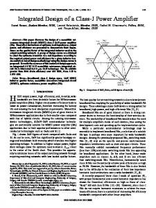
Figure 1: Uniform gate and drain line.
/wlhiN
lwog "t tW
.-A
twu
-
I.
Im
-i-lOdB. The amplifier was also unconditionally stable across the
The degradation of the output power and PAE was mainly due to the amount of current flow to the load. As illustrated in Figure 5, about equal amount of current flow both terminations (load and dummy) at operating frequency band. Also, each FET device was not operated at its optimum load impedance.
FREQ=1OOMHz
0. 15~ o.
operating frequency.
0.10-
0.05-
P- 0.00-....
-I ...... -0.05-...
,1
0-
-20-
S22
0.0
-60-
0.8
1.0
1.2
1.4
1.6
1.8
2.0
FREQ=600MHz
Load
0.05-
P
0.00-0. 05 -0.10
...........
Dummy
-0.15 0.0
6-
0.2
0.4
0.6
0.8
1.0
1.2
1.4
1.6
1.8
2.0
time, sec
4-
Figure 5: The behavior of current flow at dummy and load termination for uniform DA.
2-
2-
4-0.2
0.0
0.2
0.4
0
08
10 12
0.6
0.8
1.0
1.2
Figure 3: Small signal performance of conventional DA.
3. Large Signal Design The amplifier was then simulated with harmonic balance simulator. An input power of 17dBm was injected to the input gate line and the amplifier was biased in class AB operation. As pointed out in Figure 4, a uniform DA has demonstrated a critical degradation of the output power and power added efficiency (PAE) performance at the upper end of the operating band. 30
4-7_
X
=
30
_
328
L26
28-
24 -22 ~
26-
V~~~~~~~~~~
m -~~~~~~~~~20
24-
18
16
22
14
100
0.6
0.10-
10-
na.0
0.4
0. 15-T
-40
freq, GHz
E
!Load
time, sec
-80--50 0.1 0.2 0.3 0.4 0.5 0.6 0.7 0.8 0.9 1.0
-0.4
0.2
-30
s
my
-0.15--
-20
-40-
D
-0. 10-
--l0
200
300
400
500
600
700
800
In order to improve the efficiency and power output of a distributed power amplifier, a non-uniform distributed amplifier was designed, where the drain line impedance was tapered from section to section as illustrated in Figure 6 [6]. Impedance tapering forces the backward traveling current to zero theoretically at the dummy termination, thus forcing all of the developed current from each FET to propagate in the forward direction only. The tapered drain line impedance was designed such that each stage's cutoff frequency must be maintained similar. To do this, the line inductance should be tapered down whereby the capacitance should be tapered up as illustrated in Figure 6. Therefore, additional shunt capacitor must be added for second stage onwards to increase the total capacitances. The characteristic impedance of the first stage was 50Q as to achieve maximum cut-off frequency of the drain line. Hence, the load impedance for 3 stages DA has to be 16.67Q. Two stages LC broadband matching network was then added to transform the 16.67Q2 to standard 50QK load impedance. The complete schematic for nonuniform distributed power amplifier is shown in Figure 7. By tapering the drain line characteristic impedance, the optimum load impedance for output power and efficiency can be presented to each FET device.
FREQ, MHz
Figure 4: Large signal performance of conventional DA.
59
U/2
La
L d&
T1Aci
[L
L=
Z
L&
e
dt T2
4. Experimental Results
pt
The distributed power amplifier was then optimized using Motorola's proprietary non-linear models for lumped components, such as capacitors, inductors and resistors, and transmission line models from built-in ADS elements, microstrip line (MLIN) and microstrip TEE (MTEE). Optimization of component values and microstrip line geometries are necessary to achieve the required performance in a fabricated amplifier. Figure 10 shows a three-stage distributed power amplifier fabricated using FR4 printed circuit board (PCB).
Figure 6: Tapered drain line.
Figure
7: Schematic of non-uniform DA.
The simulation results for output power and PAB
amplifier
for this
given
are
drain line distributed power
improvement in power and operating frequency
in Figure 8. The tapered amplifier show significant PAB especially at high end
relative to that achievable with
uniform DA. 4U-
m
a1
01
-
-O
35-
30
30-
.25
20-
-15 800
0
100
200
300
400
500
600
700
Figure 10: Fabricated board for three-stage distributed power amplifier.
FREQ, MHz
Figure 8: Large signal performance of non-uniform DA.
The improvement of output power and PAE can be easily understood as most of the current were flow to the load termination with relative to the current flow to the dummy termination as depicted in Figure 9.
FREQ=100MHz
04
024
Figure 11 shows the simulated and measured large signal performance. With input power of l7dBm and supply voltage of 7.5V, approximately 1 Watt output power with PAE of about 26% was achieved over the 100-600MHz frequency band. 32-
E
m 0°2-
C)
Measured
31-
-1
O 0-
02
30-
e Simulated
2928-
...........
-0
27-
-06-
100
00
02
04
06
08
1.0
1.2
1.4
1.6
200
300
1.8 20
400
500
600
700
FREQ, MHz
time, sec
30 28-
u1 0-
Measured
2624-
Simulated
C-)
22-
-0.2-
Load -0.400
02
04
06
08
10
time,
1.2
1.4
1.6
1.8
100
20
200
300
400
500
600
700
FREQ, MHz
sec
Figure 11: Simulated and measured large signal performance.
Figure 9: The behavior of current flow at dummy and load termination for non-uniform DA.
60
The simulated and measured small signal performance is shown in Figure 12. The result shows that the measured input and output return loss were more than 10dB and 5dB respectively. Also, the amplifier was unconditionally stable with K factor more than 1 across the frequency band. Even though the small and large signal simulation results were not closed to actual performance, it made the simulation to predict the trend. Verification has been made that simulation trend was closed to actual measurement. 6Simulated
10
3'
Measured ,-V' 100
200
300
400
500
Simulated
600
700
Measured 800
0.0 0.1 0.2 0.3 0.4 0.5 0.6 0.7 0.8 0.9 1.0
freq, MHz
Simulated
freq, GHz -
Meas, uI W Masured
Simulated .
freq, GHz
+
Measured freq, GHz
Figure 12: Simulated and measured small signal performance.
5. Conclusion This paper successfully demonstrated the design of distributed power amplifier based on large signal
approach. By implementing the tapered drain line, the design has better performance in terms of output power and efficiency with relatively to uniform DA. 1 Watt output power with 13dB associated gain and 26% PAE over 100MHz to 600MHz frequency are well demonstrated.
References [1] W.S. Percival, "Thermonic valve circuits," British Patent No. 460562, Jan 25, 1937. [2] J.B. Beyer, S.N. Prasad, R.C. Becker, J.E. Nordman, and G.K. Hohenwarter, "MESFET distributed amplifier design guidelines," IEEE Trans. Microwave Theory Tech., vol. MTT-32, pp. 268-275, Mar. 1984. [3] Datasheet of RDO1MUS 1, Mitsubishi. [4] T.Y. Wong, Fundamentals of Distributed Amplification, Artech House, 1993. [5] Y. Ayasli, S.W. Miller, R. Mozzi, and L.K. Hanes, "Capacitively coupled traveling-wave power amplifier," IEEE Trans. Microwave Theory Tech., vol. MTT-32, pp. 1704-1709, Dec. 1984. [6] Lei Zhao, A. Pavio, B. Stengel, and B. Thompson, "A 6 watt LDMOS broadband high efficiency distributed power amplifier fabricated using LTCC technology," Microwave Symposium Digest, 2002 IEEE MTT-S, vol.2, pp. 897-900.
61