simple operation, management and installation, which ensured low costs of ownership. ... is a Layer 2 (or Layer 3) device controlled by SNMP and. HTTP. The device ... Free Space, Okumura, SUI and other) should be used for well defined signal ..... procedures and radio planning tools for the INEA WiMAX network. He also ...
Paper
Lessons Learned from WiMAX Deployment at INEA
Karol Kowalik1, Dawid Dudek1 , Michał Kołodziejski1 , Bartosz Musznicki1 , Eugeniusz Grzybek1 , and Jacek Jarzina2 1
2
INEA S.A., Poznań, Poland Tele-Com Sp. z o.o., Poznań, Poland
Abstract—Home broadband access is continuously demanding more bandwidth fueled by video streaming, entertainment and gaming applications. In 2010, a company INEA decided to roll-out new WiMAX-based services aimed to meet the needs of home users across the Wielkopolska region of western Poland. It was decided to follow the 802.16e standard and the Time Division Duplexing (TDD) mode that offer the ability to adjust the downlink/uplink ratio and thus are well suited for data transmission. After an extensive testing period of equipment from various vendors, engineers at INEA have chosen the Motorola (currently Cambium Networks) PMP320 solution because it is compact and its components are space- and energy-efficient. The company choice was also influenced by its simple operation, management and installation, which ensured low costs of ownership. So far, this deployment has provided fast and affordable connectivity for Internet and telephony services to around 5,500 households across the 30,000 sq. km region. After 3 years of experience, INEA would like to share the lessons learned from this roll-out. radio
capacity,
radio
planning,
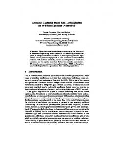
1. Introduction Currently mobile WiMAX, as defined by the IEEE Standard 802.16e-2005 [1], is a well-established wireless technology for providing both fixed and mobile access. In Poland, most of WiMAX deployments use 3.400–3.800 GHz band. This follows a decision to publish a public tender for 3.5 MHz channels from 3.600–3.800 GHz band issued by President of the Office of Electronic Communications (UKE in Polish) in 2007 [2]. The Marshal Office of the Wielkopolska Region decided to participate in this public procurement, and is currently sharing its channels with the local operators: INEA, Promax, and ASTA-NET. Despite the fact that the 802.16e standard supports mobile access, the Polish WiMAX networks provide only fixed or nomadic access. This is due to high cost of achieving coverage that would offer mobile access in 3.600–3.800 GHz band. Since 2010 INEA has started to roll-out its WiMAX 802.16e network. The network is based on the Motorola (currently Cambium Networks) PMP320 solution and supports mostly data and VoIP transmissions. An example of INEA’s base station is presented in Fig. 1. As it is shown in Table 1, the INEA WiMAX network currently supports 5,500 users. The network consists of 72 WiMAX stations and 252 access points (AP) being in34
Fig. 1. One of INEA’s WiMAX base station.
Table 1 INEA WiMAX network in numbers
Stations/Towers
In total
In Poznań
72
11
Access points/Sectors
252
32
CPEs
5500
1000
22
30
Average CPEs per AP
Number of active CPEs
Keywords—interference, WiMAX.
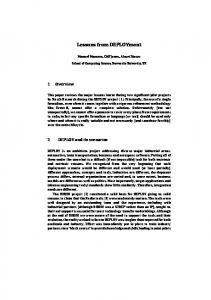
5550 5450 5350 5250 5150 5050 0
2
4
6
8
10 12 14 16 18 20 22 24
Fig. 2. Number of active CPEs (users) within 24 hours on 26 January 2014.
Lessons Learned from WiMAX Deployment at INEA
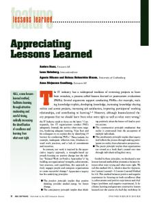
WiMAX receiver Radio link Wi-Fi router
WiMAX wireless connection
Fibre optic cable WiMAX transmitter
WiMAX receiver
WiMAX wireless connection
Fibre optic cable
PCs with Wi-Fi
Wi-Fi router
PCs with Wi-Fi
WiMAX transmitter
Fig. 3. General topology of INEA WiMAX network.
stalled across the region, which gives the average number of 22 clients per AP. In the city of Poznań it provides services to more than 1,000 clients, using 11 base stations with 32 AP. Figure 2 shows the changes in the number of active users within 24 hours. The connection between our core network and the WiMAX station is executed either using a microwave link or optical fiber connection. The latter option is most commonly used by INEA, since it is more stable and resilient. The base station realized using Cambium Networks PMP 320 products is composed of: Cluster Management Module 4 (CMM4), GPS antenna, and a number of access points with attached antennas. The CMM4 is a managed L2 (or L3) device that provides power and GPS synchronization for APs. Physically, it consists of two separate devices: EtherWan and Motorola CMM. EtherWan has 12 FE (Fast Ethernet) ports and 2 GE (Gigabit Ethernet) ports. PMP 320 AP is a Layer 2 (or Layer 3) device and it has a 90 degree antenna attached. The configuration of Transmit/Receive Transition Gap (TTG) and Receive/transmit Transition Gap (RTG) guarantees to achieve a maximum range of 15 km for 7 MHz channel. The definitions of INEA’s set of service flows are stored on each and every AP. Customers are provided with Cambium Networks 3630SM (or 3530SM). This CPE (Customer-Premises Equipment) is a Layer 2 (or Layer 3) device controlled by SNMP and HTTP. The device allows to achieve maximum throughput of 11/5 Mb/s. Customers also have the ability to use VoIP services using dedicated ertPS (Extended Real-Time Polling Service). This service is realized using Linksys SPA2102 VoIP gateways. A diagram of the network is shown in Fig. 3. In this paper the technical lessons learned from the roll-out are presented. The article does not intend to present any procedural or psychological challenges which the authors needed to overcome in order to allow INEA – cable operator to introduce wireless technology into its portfolio.
Despite quite extensive number of research papers [3]–[11] which evaluate theoretical performance or present system level analysis of WiMAX systems, authors of this paper are not aware of similar deployment analysis being published so far.
2. Radio Planning Radio planning is an essential aspect of maintaining optimal network coverage and capacity. In real WiMAX networks, especially in high density areas, radio planning is a major challenge for the operator. Before setting up each station, radio planning should at least consist of the following elements: – a determination of the total coverage of each base station and each of its sectors separately, – a preparation of the list of addresses in coverage area of each base station (BS), – channel allocation for (new or changed) sectors of each station, – a determination of (or a change in) the set of radio parameters for each coverage sector: azimuth, tilt and other constraints if applicable. The key task is to choose a proper method for a determination of areas to be served by each radio station (access point). This procedure is called a “coverage prediction”, but the term is rather meant to denote the use of one of commonly used propagation algorithms and models. Previous studies (e.g. [3], [6], [7], [9]) have show that commonly known algorithms cannot be simply used for WiMAX networks. Summarizing the conclusions of mentioned papers, for gigahertz bands and WiMAX standard some of the algorithms give results close to real performance in urban area while others in suburban or rural area. The key point is modeling the path loss in LOS and NLOS condition: 35
Karol Kowalik, Dawid Dudek, Michał Kołodziejski, Bartosz Musznicki, Eugeniusz Grzybek, and Jacek Jarzina
each of the models under studies (Ericsson 1999, COST, Free Space, Okumura, SUI and other) should be used for well defined signal path conditions – either LOS or NLOS. But in real life scenario both propagation conditions occur simultaneously for each access point sector. Over the last three years even the authors have been continuously working on improving the propagation models (starting from ITU-R P.1546 and ITU-R P.1812, SUI [4]). Despite the three-year effort, the real live conditions didn’t match with the theoretical results. Hence, INEA’s radio planning team was forced to create its own unique procedure of finding service areas round the station. The procedure nowadays uses as a basis a combined model composed of a modified free space model and a diffraction term in order to match real-live installation success and failure rates. Having taken into account signal levels measured by terminals (CPEs) installed in different locations, including different cities, towns and villages, the team were in position to construct a useful algorithm based on an algorithm previously constructed and a selected model parameter list. The basis for the model was provided by one of broadcast models used in Germany [12]. Because of various installation and propagation conditions, such a model obviously does not give accurate results, but thus prepared prediction is good enough to become a basis for acquiring new subscribers in a given area. To minimize the risk of launching a marketing action in a wrong part of the area, it was divided into two sub-areas: the zone near the station, where the probability of good reception (in both directions of transmission) is high, and the outer ring, where the risk of unsuccessful installation is higher, but still there are reasonable grounds for an attempt to acquire new subscribers. In Fig. 4 both areas are depicted in two shades of gray. The described method for a determination of the coverage around each station gives surprisingly good results.
Fig. 4. Example of results of coverage prediction.
36
Another set of radio planning issues is the channels allocation for each sector. This is relatively simple for rural sites, or generally for sites located far away from other stations using the same channels. In such cases the network may use the widest possible radio channels provided by the equipment (PMP320 AP and CPE), i.e. 10 MHz. A wide channel provides high throughput for subscribers but, at the same time, has some disadvantages as well. The basic quantum of spectrum given by the regulatory office is 3.5 MHz. Thus, for 10 MHz useful spectrum a four such basic neighboring elements were used, which means that 4 · 3.5 − 10 = 4 MHz (two sections of 2 MHz each) remains unused. In very dense areas the problem is not trivial, because the channel allocation layout may look like the one depicted in Fig. 5 where the same radio channels use the same hue.
Fig. 5. Poznań.
Example of a dense network in large urban area of
In such cases the 4 MHz of spectrum can not be wasted, as described above. Therefore, the authors had to decide to narrow the WiMAX radio channels down to 7 MHz. Fortunately, it still can provide the same throughput for a single subscriber as the 10 MHz channel, and the use twice as many channels as before is possible. Moreover, we have experienced that, thanks to good characteristics of the currently used WiMAX radio equipment, the use two neighboring “halves” of previous 14 MHz block for two sectors of the same station – even if their azimuths are relatively close to each other is still possible. The introduction of each new station to the network might force some relocation of existing radio channels. Such changes should be performed with care. The issue is not difficult if a new station is created in the area so far unsupported. In some cases, however, a rapidly growing number of subscribers forces us to built a new station (or a new sector on the same location, parallel to the existing one). Sometimes the expansion can be predicted, so particular channels were often reserved for it in advance. In some areas the services offered by INEA are so attractive that the number of subscribers grows much faster than it is expected. It is always good news, but it might necessitate
Lessons Learned from WiMAX Deployment at INEA
a total reconstruction of the radio channel network in the whole urban agglomeration. Interestingly enough, that such situations occur usually in large centers, such as Poznań and Konin, that already have good wire-line infrastructure in place and thus can hardly be regarded as having no existing access to the Internet (being thus a potential market for wireless services). Each new WiMAX station in dense population areas, with existing WiMAX stations and subscribers, causes changes of assignments to a service station for many of the CPEs. If a new station is located so that the direction from subscriber location toward the old and the new station is almost the same, such a reassignment is straightforward. However, if both directions differ significantly (for instance, the difference exceeds a change in signal levels of 2 dB, taking into account the antenna patterns and change in the distance between CPE and AP), we should try to rotate the subscriber terminal antenna in a new direction. In some cases it is not possible, or too expensive, so the subscriber must remain with the assignment unchanged. The above describes one of existing limitations of the network optimization. When a radio network grows, the possibility of co-channel interferences grows up as well. To avoid this as early as at the planning stage of the radio channels assignment, we have to take into account interference range prediction. For this purpose the ITU-R P.1546 algorithm that yields reasonable results is still used. Figure 6 shows an
The interference problem is particularly important in high density areas (Poznań, Konin, further expected), not only because of the density of deployed stations. Because of the method of changing CPEs assignment described earlier, after creating a new station the operator should reassign a significant part of subscribers to the new site. As stated earlier, it is possible only for a fraction of existing CPEs. As a result, there still exist terminals associated with a “far away” station using channel interfering with the same channel used in a “near” station. In high density areas neighboring stations are located only a few kilometers apart, so this situation is relatively frequent. For such areas the radio planning team prepares a special “good assignment” map that shows areas of service for each particular sector. The operator should try to force all the terminals located in particular area to use an appropriate sector. It helps the operator keep the interference risk as low as possible. Figure 7 shows an example of the described “good assignment” map.
Fig. 7. “Good sector assignment” chart of Poznań urban area.
Lessons learned:
Fig. 6. Predicted interference areas for non-synchronized (other than our own) networks and for the own network of the operator.
example of interference range prediction for a typical foursector WiMAX station compared with useful coverage of the same station (light gray areas in the center, for explanation see above comments). Light and dark gray regions distinguish between non-synchronized co-channel interference areas and the synchronized ones.
• although for the WiMAX network, where the propagation path looks very different for each CPE and there is no single algorithm for determining coverage, a reasonable method for a prediction of a serving area for each sector and radio station have been found; • in some areas saturation of a sector occurs faster than expected – we may support the sector with the parallel one, but a better solution is to predict such situation in the initial study phase; otherwise some problems with network optimization and radio channels resources may ensue; • WiMAX network expansion is favorable for the operator and the subscribers; in dense areas, interference during switching the CPEs into a new station are hard to avoid. The radio planning team should cooperate with network administrators in determining all the possible conflicts. 37
Karol Kowalik, Dawid Dudek, Michał Kołodziejski, Bartosz Musznicki, Eugeniusz Grzybek, and Jacek Jarzina
Interference is often identified as a key cause of performance degradation in wireless networks [5], [8]. In presented network the GPS synchronization to eliminate selfinterference between neighboring APs is used. Nevertheless, the network still requires a careful radio planning in order to minimize self-interference. At the time, this was a particularly pronounced problem when the number of base stations in Poznań is increased. In [13], the vendor of the PMP320 platform provides insights into what needs to be done in order to minimize interference. Among others, the following actions that help reduce interference, are listed [13]: 1. AP down-tilt, 2. Lower AP transmit power,
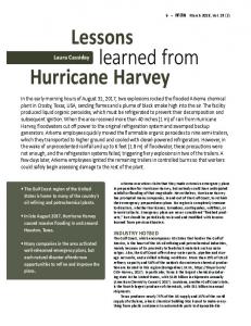
and each CPE is able to achieve about 1.8 Mb/s. This explains why spectrum is a valuable resource and needs to be properly managed. Because the three parameters: modulation, Forward Error Correction (FEC) coding and MIMO mode are changing quite frequently, hence the capacity of a WiMAX channel and its utilization also changes significantly. This can be observed in Fig. 8 that demonstrates the utilization of OFDMA symbols in the WiMAX frame. Bezier approximation
100
OFDMA frame utilization [%]
3. Interference
80 60 40 20 0 0
3. Re-orienting AP sectors, 4. CPE up-tilt to tower on especially short links as required, 5. CPEs registered to correct AP sector, 6. Lowering AP Recv target from –70 to –73 dBm. In day-to-day operation the first 5 actions is used. We also wanted to use the sixth method. So we were ready to trade uplink CINR and RSSI values for lower interference observed by other APs operating on the same channel. Therefore, after some extensive testing, the AP target receive level was decreased from –70 to –75 dBm. Despite the effort, however, we have never observed avg uplink CINR to increase on other APs. In summary, a proper radio planning is a key technique of interference mitigation.
4. Capacity Capacity in a WiMAX network is not fixed [10]. Each CPE operates with spectral efficiency that changes in time and is a product of three parameters: modulation, Forward Error Correction (FEC) coding and Multi Input Multi Output (MIMO) mode. Therefore, the radio capacity of a given AP is a function of the number of CPEs and their spectral efficiency. For example, if one CPE operates with modulation of 64 QAM, then its spectral efficiency is 6 b/s/Hz. If it is using 5/6 FEC, then the spectral efficiency is reduced to 5 b/s/Hz. If it is using MIMO-B, then its spectral efficiency is doubled and reaches about 10 b/s/Hz. The INEA WiMAX network uses 10 MHz channels. When all active CPEs use 64 QAM5/6, then the capacity is about 43.2 Mb/s. Thus, if we have 10 CPEs operating at 64 QAM5/6 and all are fully busy, then each of them is able to achieve 4.3 Mb/s resulting in the total capacity of about 43 Mb/s. However, when two new CPEs connect to give AP with modulation QPSK1/2, then the capacity drops to 21 Mb/s 38
100
200 300 400 500 600 700 Sample number [5 min interval]
800
Fig. 8. Example radio utilization of one AP.
In order to maintain high capacity, the network operator needs to control modulation, FEC and MIMO mode. Moreover, WiMAX 802.16e products do not implement load balancing functionalities. Soft handoff of CPE allows the connection to be re-established though does not offer load balancing functionality across APs covering the same area. Due to this limitation, INEA has implemented the following mechanisms that help maintain high capacity: – fixed assignment of CPEs to AP by fixing frequency or BSID, – assignment of CPEs to AP, which allows for the highest modulation, FEC and MIMO mode, – monitoring of radio capacity (utilization of OFDMA symbols). It is only when the operator uses mechanisms similar to those developed by INEA that it is possible to maintain a high capacity WiMAX network. Moreover, only properly planned and restricted installation conditions allow the operator to fully exploit MIMO multi antenna technology and OFDMA technologies for providing maximum throughput in multi-path environment. Chaotic roll-outs result in networks with unpredictable capacity level.
5. Signal Strength In the INEA WiMAX network each AP is transmitting at maximum power, but CPEs transmit power is not fixed and it is controlled by Auto Transmit Power Control (ATPC). ATPC is a mechanism implemented by vendor (Cambium Networks) in order to allow each AP to control the output power of all connected CPEs. AP tells each CPE to transmit with such an output power so it can receive it at the
Lessons Learned from WiMAX Deployment at INEA
-70 dBm N-k CPEs transmit at reduced power (ATPC)
40 30
DL RSSI - UL RSSI
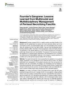
target receive level of –70 dBm. It was expected that out of N active CPEs, the k-furthest CPEs (or those that were operating in non-line-of-sight (non LOS) environment) would transmit at the maximum power (+27 dBm), whereas the other remaining N − k CPEs would operate with reduced power, as shown in Fig. 9.
k CPEs transmit at maximum power
CPE(1) CPE(2) CPE(3) CPE(4)
20 10 0 -10 -20 -30 -40 -100
-90
-80
-70
-60 -50 DL RSSI
-40
-30
-20
Fig. 10. DL RSSI vs. DL RSSI – UL RSSI.
CPE(N-1) CPE(N)
Distance [km] 100
40
Fig. 9. ATPC – Auto Transmit Power Control.
Received Signal Strength Indication (RSSI) is the measurement of the received power present in a radio signal. These measurements were collected from all CPEs in order to evaluate their performance. Both downlink RSSI measurement (DL RSSI) and uplink RSSI measurement (UL RSSI) can be expressed by the following simple formulas:
DL RSSI - UL RSSI
30
10
-20 20
RSSIUL = TXCPE + AntennaGCPE − Pathloss + AntennaGAP (1)
-40 -30
(2)
When the AP transmits at its maximum power (+25 dBm) and the CPE is transmitting at its maximum power (+27 dBm), we obtain: RSSIDL − RSSIUL = 25 dBm − 27 dBm = −2 dB .
(3)
However, since the CPE TX power is controlled by ATPC, then its TX power is ≤ +25 dBm, therefore: RSSIDL − RSSIUL