Wavefront coding (WFC) is a powerful hybrid optical-numerical technique for ..... coding (up) and denoised image using the measured noise PSD (down); c) Two ...
Low-cost Wavefront Coding Using Coma and a Denoising-based Deconvolution Carlos Dorronsoro1, Jose A. Guerrero-Colon1,2 , Marta C. de la Fuente3, Jose M. Infante3, Javier Portilla1,4 1
2
Imatrics Image Technologies, Madrid, Spain Department of Computer Science and Artificial Intelligence, Universidad de Granada, Spain 3 Indra Sistemas, Aranjuez, Madrid, Spain 4 Instituto de Óptica, Consejo Superior de Investigaciones Científicas, Madrid, Spain ABSTRACT
Wavefront coding (WFC) is a powerful hybrid optical-numerical technique for increasing the depth of focus of imaging systems. It is based on two components: (1) an optical phase element that codifies the wavefront, and (2) a numerical deconvolution algorithm that reconstructs the image. Traditionally, some sophisticated optical WFC designs have been used to obtain approximate focus-invariant point spread functions (PSFs). Instead, we present a simple and low cost solution, implemented on infrared (IR) cameras, which uses a decentred lens inducing coma as an adjustable and removable phase element. We have used an advanced deconvolution algorithm for the image reconstruction, which is very robust against high noise levels. These features allow its application to low cost imaging systems. We show encouraging preliminary results based on realistic simulations using optical PSFs and noise power spectral density (PSD) laboratory models of two IR imaging systems. Without induced optical phase, the reconstruction algorithm improves the image quality in all cases, but it performs poorly when there are both in and out-of-focus objects in the scene. When using our coding/decoding scheme with low-noise detectors, the proposed solution provides high quality and robust recovery even for severe defocus. As sensor noise increases, the image suffers a graceful degradation, its quality being still acceptable even when using highly noisy sensors, such as microbolometers. We have experienced that the amount of induced coma is a key design parameter: while it only slightly affects the in-focus image quality, it is determinant for the final depth of focus. Keywords: Wavefront Coding, IR Cameras, Coma, Image deconvolution, Image denoising, Image deblurring.
1. INTRODUCTION In standard cameras, the optical system forms an image on the sensor plane, which directly provides the final image. Slight defocus produces a substantial drop of the image quality, especially with high numerical apertures. In infrared (IR) cameras, defocus may be produced not only by not being the target within the in-focus distance range, but also by a change of the external temperature and a subsequent dilation/contraction of the lenses or the mechanical elements supporting them. Low cost IR systems are incompatible with sophisticated (and expensive) athermalization mechanisms, thus avoiding precise focusing rings is desirable. Wavefront coding (WFC) is a powerful hybrid optical-numerical technique for increasing the depth of focus of imaging systems1,2. WFC is based on two key components: (1) An optical element that introduces a controlled amount of phase in the wavefront and (2) a digital procedure based on a numerical deconvolution algorithm that reconstructs the optical image. The phase element produces an intermediate image at the detector plane which is optically coded, i.e. degraded in a controlled manner by a known Point Spread Function (PSF). Numerical procedures (image processing algorithms) are then needed to restore the intermediate image and provide the final image. The optical phase element is designed in such a way that its associated PSF at the detector plane does not appreciably change when defocus is introduced3. Although the intermediate image at the detector has lower quality than the corresponding focussed image of a standard system, it can be restored by deconvolution, as the PSF is known. Therefore, the great advantage of WFC is that for adequate combinations of phase masks and restoration algorithms the intermediate images are insensitive to defocus and so they Electro-Optical and Infrared Systems: Technology and Applications IV, edited by David A. Huckridge, Reinhard R. Ebert, Proc. of SPIE Vol. 6737, 67370E, (2007) · 0277-786X/07/$18 · doi: 10.1117/12.738279
Proc. of SPIE Vol. 6737 67370E-1
are the final restored images. While some in-focus quality may be lost (especially for high noise regimes4,5), this loss is made up for, since a much better out-of-focus quality is obtained. WFC has been successfully demonstrated in visible light, for example in microscopy, or in low cost imaging cameras affected by chromatic aberrations2,6. Recently, some studies2,7,8 propose the use of WFC imaging techniques with IR radiation. Some characteristics of IR image cameras that make them good candidates for being enhanced using WFC are: (1) IR systems are, due to their nature, unstable in terms of focus: variations in temperature, and IR cameras including athermalization mechanisms (sophisticated optomechanical hardware to avoid defocus of the system as external temperature changes) are expensive. (2) The optical system represents a high percentage of the final cost of IR cameras. (3) IR cameras already have computational capacity, as they typically have embedded processors for running image processing algorithms to enhance the image. WFC is, thus, a promising technique to reduce the complexity of the optics, not only by avoiding costly optomechanical athermalization or refocusing mechanisms, but also by simplifying the optical design and even relaxing the manufacturing tolerances of the lenses. The goal is to loose some of the effort traditionally devoted to achieve a high image quality at the detector and shift it from image formation towards postprocessing (image restoration), which can be embedded in already existing electronic hardware. That is, WFC can be applied not only to improve the performance out of focus, but also to dramatically reduce the complexity (and, thus, the cost) of the optics while only introducing slight modifications in the embedded hardware. The application of WFC in the infrared region is inherently more complex than visible and raises some important issues, both in the optical and in the postprocessing stages. Traditionally, both in visible light and IR, focus-invariant point spread functions (PSFs) are obtained with sophisticated phase plate designs3. In IR, manufacturing plates to induce such asymmetric phase maps entail important complications regarding new materials and methods for surface shaping. On the other hand, IR cameras have both lower spatial resolution and higher noise than visible cameras. Thus, imposing and assessing certain PSF designs, in which relies the image deconvolution, cannot be as precise in IR as in visible light. There is an extensive scientific literature regarding postprocessing algorithms. The most used for WFC are variations of the Wiener deconvolution, as it represents a good trade-off between image quality and complexity. Recently, some studies4,5 have tackled the issue of wavefront coding in presence of high detector noise. Although these studies are limited to Gaussian (white) noise, they have highlighted the impact of noise in the process of image restoration. IR imaging systems are usually characterized by high relative noise levels and a noise power spectral density far from flat (i.e., non-white), which makes the process of image restoration more demanding. In this work we present a simple and low cost solution to implement wavefront coding in IR cameras, which uses 1) a decentred lens inducing coma as an adjustable and removable phase element (Section 2.1) and 2) a two-step denoisingbased deconvolution algorithm for the image reconstruction9,10,11,12 (Section 2.2). This approach has two potential advantages: (1) Although the PSF of an optical system affected by coma is, from a theoretical point of view, less efficient for WFC than other PSFs already proposed, it also has a relatively low sensitivity to focus and it has no zeros in the spatial frequency domain, which favors the deconvolution quality13 . Especially for low cost applications, where the images are affected by low resolution detectors, noise and uncontrolled blur, the approximation of using coma instead of other sophisticated designs may be practically interesting. However, the most important advantage of this solution is the practical simplicity of generating a comatic PSF. The optical phase element proposed in this study induces the optical coding with tilted or decentred conventional lenses, with spherical surfaces. Thus, the issue of manufacturing expensive asymmetric phase plates in the IR is avoided. Furthermore, as no extra element is added to the system, transmission is not degraded. Controlling the tilt or decentring results in a removable and adjustable WFC mechanism. (2) Using an advanced deconvolution algorithm9,10,11,12, which is very robust against high noise levels and can deal with non-white noise distributions, extend the range of WFC applicability with respect to using conventional Wiener-like deconvolution techniques, especially when using noisy detectors.
Proc. of SPIE Vol. 6737 67370E-2
In this paper we wxplore the feasibility of the solution for certain combinations of optical coding and detector parameters. The optical phase element and the reconstruction algorithms are described in section 2. Section 3.1 describes an experimental proof of concept with visible images captured in controlled conditions. Section 3.2 addresses the problem in the IR, with the simulation of intermediate images using the measured parameters of the detector and the design parameters of the optics. Section 3.3 tests the image reconstruction algorithm on these images. Sections 3.4 shows the WFC results for realistic noise of a low-cost detector. The procedure is also applied to a high quality IR detector (Section 3.5). The resulting thru-focus final images of these experiments are compared with the corresponding simulated images of a conventional IR camera. Section 4 discusses these results, and explores the importance of the amount of coma as a key design parameter of the system.
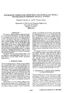
2. METHODS Figure 1 shows a schematic diagram of the low cost IR imaging system proposed in this study, incorporating WFC. It is based on a conventional low cost IR camera (solid rectangles) with some additional elements (dashed rectangles) that incorporate WFC. LOW COST PHASE ELEMENT (OFF-CENTER LENS) 1
LOW COST OPTICS
LOW COST IR SENSOR (HIGH NOISE)
INTERMEDIATE IMAGE 2
RESTORATION ALGORITHM debluring by denoising
´ ´
Blur pre-compensation Image De-noising
FINAL IMAGE
3
Figure 1. Schematic diagram of the low cost IR imaging system proposed, incorporating wavefront coding.
The first element (box number 1) is the low cost optical phase element (see section 2.1 for details). In a WFC scheme, the image at the detector (box 2) needs to be reconstructed by a restoration algorithm (box 3, see section 2.2) to obtain the final image.
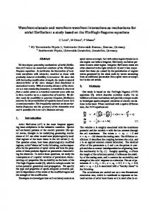
Figure 2. On-axis-coma generator plus conventional thermal camera.
2.1 Low Cost Optical Coding This work proposes to use decentred or tilted internal elements within the optical path inducing coma, as low cost optical phase elements13. If enough coma is introduced, then the PSF is made robust against aberrations and defocusing, while image processing algorithms can restore the coma-degraded image at the detector. In order to evaluate this approach, a simple and versatile system has been designed. Two elements, one plano-concave and one convex-plano lens with the same radius of curvature, are decentred one to each other by the same magnitude but opposite sign. A property of this configuration is that, being afocal, it can be placed in front of any conventional camera without affecting the camera focus adjustment. But, more importantly, the phase modulation can be adjusted by means of a variation of the lateral displacement between the two optical elements, as can be seen in figure 2. This system is a variation of that proposed by Hellmut et al.14. It can be demonstrated15 that phase change in the (X,Y) plane (i.e., at the exit pupil) is given by:
Ph _ coma _ plate( x, y ) =
⎫ ⎛ 2d d 3 ⎞ 2π ⎧⎪ d − 3 ⎟ y + ( n − 1) 3 ( x 2 + y 2 ) y ⎬ ⎨ −( n − 1) ⎜ λ ⎪⎩ R ⎝ R R ⎠ ⎭
where R is the common curvature radius and d the displacement of each plate from the optical axis. R and d, are then, through coma aberration coefficient, the main design parameters in the PSF of the system. This work describes the
Proc. of SPIE Vol. 6737 67370E-3
procedure to establish the amount of coma that optimizes the performance of the system. For that, the optical part has to be taken into account in combination with the detector characteristics, the deconvolution algorithm, the camera application, and the optical quality required. 2.2 Image Restoration Image restoration is typically formulated as the estimation of an image given a linearly filtered version of the original corrupted by additive noise. This process is usually modelled in the frequency domain as follows:
Yo(u, v) = H(u, v)X(u, v) + Wo(u, v), being H(u,v), X(u,v) and Wo(u,v) the Fourier transforms of the PSF, signal and noise respectively. For simplicity, indexes (u, v) are drop hereinafter. Due to the low-cost sensor and the strong PSF of the system, the restoration algorithm must be able to deal with heavy blur in presence of high noise levels. In this work we have used a two-step restoration method proposed by Guerrero-Colon and Portilla10,11,12: Step 1 - Global blur compensation: Performed by applying a generalized (global) Wiener filter:
where Pw0 and Px are the power spectral densities of noise and signal, respectively. The balance between noise and blur suppression is controlled by the regularization parameter alpha. Step 2 - Local denoising: After step-1 the observation yields: Because G has been optimized in the first step, no further attempt to correct the remaining linear distortion Hr = GH is made, and what is left is to denoise the prefiltered image using a non-linear algorithm9. The method assumes known both degradation parameters (PSF and Pw0), hence only two parameters (α and Px) must be estimated. α is estimated off-line by training with a set of standard images, which yields a very robust value for a wide range of degradation (both blur and noise). We use for Px the simple (and well known) k/f2 model, where f represents absolute spatial frequency and k is a constant that ensures consistency with the original estimated variance. Summarizing, the chosen method is very effective, and it has shown robustness against a wide variety of noise levels and PSF’s. It is also efficient and non-iterative, so it has a strong potential to be used as a real-time restoration algorithm, when combined with efficient denoising algorithms. Furthermore, to the best of our knowledge, it provides state-of-theart performance for the common simulation experiments in the literature10,11. 2.3 Experiments 2.3.1 Visible camera The goal of these initial studies in visible light was to test if the algorithms selected for deconvolution10,11,12 were able to restore a real image severely affected by coma, its robustness against noise, sampling, or bit depth reduction. For this purpose, a tilted singlet (f=50mm) was placed in front of a high quality digital CCD camera (Hamamatsu ORCA 100). The PSD of the noise was calculated, following standard procedures, from images of uniform scenes. This was made for single frames, and also for averages of images resulting in highly reduced noise. The PSF of the system was experimentally obtained from images of pinholes with variable diameters and luminance. Different objects, generated by a high brightnerss minidisplay (LiteEye), were placed in the object plane of the system (3 meters away from the lens). This procedure allows a precise control of the objects to be imaged, and an immediate reference for algorithm evaluation: the ideal non-degraded version of the object. With this distance configuration, each
Proc. of SPIE Vol. 6737 67370E-4
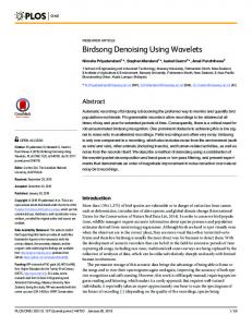
pixel of the camera subtended more than 10 pixels of the minidisplay, so sampling effects can be neglected. 30 images were taken for each object. Different combinations of coma and defocus where tested, by changing the tilt and the object position, respectively, to demonstrate the capability of the algorithm to manage the resulting PSFs. To study blur compensation in ideal conditions the full resolution of the image was used, and 30 frames were averaged to reduce noise. The noise effect was then assessed by processing single frames. Sampling influence was studied by reducing the image resolution to a half, and also the effect of a bit depth reduction from 12 to 8 bits (see results in section 3) 2.3.2 Simulation of IR images Realistic simulated IR images were obtained considering the coma subsystem described in section 2.1, in combination with a conventional IR objective (f/1, EFL 75mm and FOV 11º x 8º), and a 320 x 240 microbolometer sensor (45µm pitch), which provides 8 bit visible images, affected by non-white noise. Some of the PSFs used in the simulations are shown in figure 3. They were obtained from the optical design of the system, including the low cost adjustable/removable phase element with variable R and d for the coma subsystem. Polychromatic IR radiation was used to obtain the PSFs, that where then scaled to the pitch size of the detector and normalized. The PSD of the noise was calculated from laboratory images of uniform backgrounds. A different random noise pattern was computer-generated for each frame, and added to the simulated intermediate (optically degraded) image. Both PSF and noise PSD were applied to a set of high resolution and low noise IR Images (from Merlin InSb 9705 and Phoenix LF InSb 9803).
Figure 3. Some of the PSFs used for the simulation, with variable amounts of coma and defocus
2.3.3 Simulation of the Wavefront Coding process Several experiments where performed to assess the limits of the restoration process. Different amounts of optical coma were simulated, by applying different spatial scale factors (8x, 4x, 2x, 1x and ½ x) to the realistic PSF. 8x corresponds to the high resolution PSF provided by the optical design program (Code V). This simulates different spatial extents of the PSF relative to the detector grid. Several noise factors were applied (2x, 1x, 0.5x, 0.25x, 0.10x) to the realistic simulated noise obtained with the measured PSD. The two-step deconvolution algorithm was compared to conventional Wiener filtering. Two cases were studied in detail: a realistic low-cost camera and a low-noise sensor with the same optics. To study the first case, the images were simulated using the measured noise characteristics of the existing microbolometer-based MVT IR Camera (INDRA, Aranjuez, Spain), and the design parameters of the optics (modified with the addition of the comatic phase element). Thru-focus PSFs were used, to explore the image quality out of focus. The second case (high quality sensor) was simulated with the same parameters, except the amount of noise, which was diminished by a factor of 10. In the restoration/deconvolution process was either assumed that the amount of defocus was known (which doesn't really reflect the real conditions) or a blind approach (as in wavefront coding typical scenario) where the defocus is unknown and, thus, the same PSF (tipically the in-focus-PSF) is used for the deconvolution of all the intermediate images. The resulting images were compared to the conventional IR camera approach, that doesn’t use any phase element.
Proc. of SPIE Vol. 6737 67370E-5
3. RESULTS 3.1 Image Reconstruction: Visible Figure 4.a shows the intermediate image captured with the 12-bits visible CCD detector (one frame). The lens tilt was adjusted to get an intermediate image severely affected by coma. The measured PSF subtended more than 50 pixels on the image. The resulting images after the two step denoising based deconvolution are shown: 4.b) low noise (the intermediate is obtained after averaging 30 frames), 4.c) high noise (one single frame), 4.d) High noise and subsampling to half the initial image resolution in both spatial dimensions. A bit depth reduction from 12 to 8 bits has no appreciable effect on the final images. As an example, Figure 4.d shows the result of restoring a high noise and reduced resolution image, from a 12 bit (up) or 8 bit (down) intermediate image. a) Intermediate Image
b) Low noise restoration
c) High Noise restoration
d) Sampling
Figure 4: Image restoration of real images affected by coma: See text for details.
In low-noise conditions (4.b), the reconstruction method produces a very important visual improvement in the image, as it is able to recover much detail that was lost by optical blur in the intermediate image (4.a). When high noise is present (4.c), some wavelet-type artifacts appear, but the improvement is still important. The method is robust against subsampling of the intermediate image to half resolution (4.d up) and quantization to 8 bits (4.d down). 3.2 IR simulated images Figure 5.a shows a high contrast image of an homogeneous object, taken with the MVT IR Camera (up), and simulated from the noise PSD of its detector (down). Both images, real and simulated, are different because correspond to different noise samples, but share the same statistics. a) Noise observation and simulation
b) Noise reduction (PSD Test)
c) Simulated images
Figure 5: Noise simulation. a) laboratory observed (up) and simulated (down) detector noise; b) real laboratory image without optical coding (up) and denoised image using the measured noise PSD (down); c) Two simulated noisy IR images with realistic noise.
Proc. of SPIE Vol. 6737 67370E-6
In order to validate the noise description, the PSD was used to denoise a real image (Figure 5.b). The two-step deblurring by denoising method was applied to the real image (up), with a Dirac delta as PSF, to inactivate the deblurring process. The resulting image (down) represents a good estimation of the scene, with noise dramatically reduced. This result represents a simultaneous validation of the PSD used, and the second step of the restoration algorithm for IR images. Figure 5.c shows two examples of simulated images with realistic noise. These simulated images have similar appearance to the real image shown in 5.b up. No optical blur has been simulated in figure 5. To simulate blur, image is convolved with the simulated PSF prior to the addition of the noise. Different combinations of noise and blur can be obtained by scaling the PSF (spatial support) and applying a multiplicative factor to the simulated noise. Figure 6 shows three examples. From left to right: low degradation (PSF ½ x -7x7 pixels- and noise ¼ x); realistic degradation (PSF 1x -16x16 pixels- PSD 1x); and severe degradation (PSF 2x -32x32 pixels- PSD 2x).
— T, — Figure 6: Examples of simulated degradation, including detector noise and optical blur: low degradation (left), realistic simulation (center), and severe degradation (right).
3.3 Image reconstruction: IR The two-step deblurring-by-denoising was applied to the simulated degraded images, and compared to Wiener filtering. In all cases, Wiener filtering introduces severe artifacts in the image. Figure 7 shows the results for two images with different levels of degradation. In the rest of this manuscript, the results of the Wiener filtering are not shown, as this method is worse adapted to these image degradations. a) Wiener
b) Guerrero-Colon & Portilla
.c) Wiener
d) Guerrero-Colon & Portilla
Figure 7: Comparison of restoring algorithms (see text for details).
3.4 Wavefront Coding process with realistic noise Figure 8 shows the results of the image restoration of the intermediate images simulated with realistic parameters for the MVT Camera with the low cost phase element. Even when there is no need for blur compensation, in focus and without optical coding, the algorithm improves the quality of the images by reducing the noise, as already seen in figure 5.b. Two out-of-focus positions are shown in figure 8. “High defocus” corresponds to the full defocus shift expected for thermal dilation/constriction of the optomechanical elements, and “moderated defocus” to half of that. Without optical coding and out of focus, the intermediate (degraded) image at the detector suffers a substantial drop in optical quality. As
Proc. of SPIE Vol. 6737 67370E-7
expected, the defocus blur cannot be correctly compensated and many artifacts are introduced in the reconstruction process, even if the defocus PSF is precisely known. The reason is that the defocus PSF has zeros in the frequency domain which make the deblurring step difficult. With optical coding, the quality of the intermediate image is much more stable thru-focus. Thus, the final image quality out of focus is much better, after reconstruction, than that of a standard system. This is due to the characteristics of the comatic PSF, better suited for image deblurring than the defocus PSF of a corrected system. As a consequence of the PSF stability thru focus induced by coma, the guided reconstruction (in which the amount of defocus is known, and therefore there is a precise knowledge of the PSF) and the blind reconstruction (in which there is no a priori knowledge of the defocus state) end up with similar image quality. This result is decisive for the viability of a low cost design based on the solution proposed in this work. The in focus PSF can then be used in a broad range of focus positions, and neither correction nor control of the focus state is needed. Images with asterisk in figure 8 illustrate the main advantages and drawbacks of using WFC with low cost detectors. The in-focus image quality of a conventional system usually has the maximum resolution allowed by the detector, but is affected by noise. When WFC is used, the process of optical blurring and digital deconvolution in presence of noise yields an image with slight resolution loss, but also with reduced noise. With high defocus, the conventional system produces a completely blurred image, while the WFC system retains most of the image quality in focus. The artifacts appearing in all the reconstructed images, are related to the presence of high noise in the deblurring process. The following section explores how a better detector with lower noise figures could improve the reconstruction process. 3.5 Wavefront Coding process with low noise As expected and shown in figure 9, WFC provides much better results when detector noise decreased. In these simulations, the same PSFs were used, but the noise factor used was 0.1. Comparing the images of a standard system (first row) with the final images in a WFC scheme (last row), the conclusions are different now than those of previous section. With low noise, the image quality in focus with WFC has the same quality as that of a conventional system. Out of focus, the differences are dramatic. While in a conventional system high spatial frequencies are lost, with WFC the effective resolution of the image is almost unaltered, and only minor artifacts are introduced in the image.
4. DISCUSSION The performance of the proposed WFC system strongly relies both on the correct optical coding induced by the low-cost phase element and on the restoration process by the deconvolution algorithm. Despite the latter had been carefully verified for simulated experiments involving natural images in the visible spectrum11, it was crucial to test it under real conditions of IR images. Experiments in section 3.1 show that the method can correctly deal with real degradations in visible detectors, and that it is also robust against other kind of degradations such as sampling, and bit-rate reduction, usually found in IR. Nevertheless it must be noted that the final performance is conditioned by the quality of the estimation of the degradation parameters (PSD and PSF). As shown in Figure 5.b, the algorithm is also suitable for restoring real IR images under heavy noise, which in turn means that the algorithm is appropriate for low-cost IR detectors. Note that in this case no blur compensation has been applied to the image, as the noise widely dominates the image degradation. Finally, Figure 7 includes a full restoration example in IR with our method (with simulated images including different combinations of noise and optical blur), which clearly surpasses other well known method. Regarding the image quality, we have shown that the algorithm is able to successfully compensate heavy noise and optical blur separately. A denoising example with a real IR image can be seen in figure 5.b, and Figure 8 -in focus, with no optical coding- shows the result on a realistic simulated IR image. Blur compensation results (in low noise) can be seen in figure 2.b for real visible images and figure 9 -last row- shows three results on simulated IR images. But the combination of both, blur and noise, may be harmful. In general, the quality of the blur compensation relies heavily on the noise level and the little the noise, the better the performance. In all the restored images of Figure 8, we can detect wavelet-like artifacts, which are due to the deconvolution in presence of high noise levels. Figure 9, in contrast, has no artifacts, except for the high defocus case.
Proc. of SPIE Vol. 6737 67370E-8
Moderated defocus
High defocus
* ! ':
*
—. I,.
'— 1
I
Blind reconstruction
WFC Guided Reconstruction
Intermediate image
Conventional System - Wihout optical coding Guided reconstruction Intermediate image
In focus
*
* Figura 8: Restoration results. See text for explanation.
Proc. of SPIE Vol. 6737 67370E-9
Moderated defocus
High defocus
WFC Final Image
WFC- Intermediate Image
Conventional System
In focus
Figure 9. Low Noise restoration
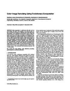
As already pointed out, the key design parameter in this WFC scheme is the amount of coma. High coma yields in large PSF’s. This has a double effect; on the one hand, the intermediate images become less sensitive to defocus; on the other hand, the in-focus image quality decreases. Figure 10 illustrates this fact. Different amounts of coma (4x, 2x, 1x, ½ x) produce, for the same amount of realistic noise, a progressive decrease of in-focus image quality. We point out that this effect strongly depends on the noise level, and in the case of very high quality detectors, this counter-effect is negligible (as shown in Figure 9, botton left panel). When dealing with low-cost detectors for WFC, is critical to find a good compromise between the detector noise (PSD) and the amount of blur (PSF). In that way, the scheme presented here is very flexible. The use of tilted or decentred optical elements, besides being a simple and inexpensive solution, allows us to adjust the amount of optical coding, and to explore the trade-off between depth of field and in focus image quality. Furthermore, the optical blur, and thus the WFC effect can be reduced to zero. As all the denoising capabilities of the electronics are maintained, the maximum image quality can be recovered at any time. Then, the coma-based optical coding proposed here represents an appealing alternative to other solutions like phaseplates, which although could produce a better WFC effect, are neither removable nor adjustable, and they may be difficult to manufacture in IR. In the example presented here both detector and optomechanical layout were defined in advance, and the optimal performance is obtained with an amount of coma whose PSF subtends around 15 pixels on the detector, depending on the image content. As future work, this key design parameter will be used to process real IR noisy intermediate images. There are some issues, not appearing in simulated images, that
Proc. of SPIE Vol. 6737 67370E-10
could arise in a real implementation. Among them: variations of the PSF along the field of view, changes in the noise PSD with the electronic gain or the non-uniformity correction applied to the image, sampling/aliasing problems, or artifacts due to bad pixels. These are important practical issues for further research. Coma 4 x
Coma 2 x
Coma 1 x
Coma ½ x
Restored image
Detector image
Coma 8x
Figure 10: In-focus image quality versus the amount of coma, for realistic noise
5. CONCLUSIONS We have presented a simple and low cost wavefront coding (WFC) solution, implemented on infrared (IR) cameras, which uses a decentred lens inducing coma as an adjustable and removable phase element. We have used an advanced deconvolution algorithm for the image reconstruction, which is very robust against high noise levels. We have demonstrated through realistic simulations that the proposed scheme significantly reduces the final image quality degradation caused by defocus. We have tested, with different amounts of defocus, two situations: heavy noise and moderate-low noise. In both scenarios the added optics combined with the numerical deconvolution result into a strong image quality improvement. Severe defocus and/or noise produce a graceful image degradation. For highly noisy IR simulated images, even in the absence of defocus, the proposed scheme dramatically improves the image quality, because of the powerful denoising applied. We have experienced that the amount of induced coma is a key parameter design. Although it only moderately affects the in-focus image quality, it is determinant for the final depth of field. It also has a direct influence on other design parameters, as the amount of computation per frame, or the sensor size. Summarizing, the proposed solution is robust, flexible, inexpensive and very effective, and we believe it may become an alternative to more sophisticated WFC schemes in many practical cases. Future development and spread of this kind of hybrid capture-processing techniques will depend on the availability of highly efficient implementations of advanced numerical deconvolution / denoising algorithms, especially when aiming to design real-time response cameras.
Proc. of SPIE Vol. 6737 67370E-11
6. ACKNOWLEDGEMENTS Work described in this paper was supported by the Spanish MoD COINCIDENTE program DN8644. JAGC is funded by AP2005-2969 FPU fellowship (M.E.C.). JP is funded by the “Ramón y Cajal” Program (M.E.C.). JAGC and JP are also funded by TEC2006/13845/TCM (M.E.C.) grant. Thanks are due J. M. Lazaro (INDRA) and to F. Márquez (Testing Laboratory, CIDA) for previous collaborations and technical support.
7. REFERENCES 1. E. R. Dowski and W. T. Cathey “Extended depth of field through wave-front coding” Applied Optics Vol. 34, Nº 11, pp. 1859-1866 (1995) 2. W. T. Cathey and E. R. Dowski “New paradigm for imaging systems” Applied Optics Vol. 41, Nº29, pp. 6080-6092 (2002) 3. S. S. Sherif, W. T. Cathey, and E. R. Dowski, "Phase Plate to Extend the Depth of Field of Incoherent Hybrid Imaging Systems," Appl. Opt. 43, 2709-2721 (2004) 4. S. Bosch, R. Tudela, M. C. de la Fuente, J. Ferré-Borrull, “Impact of the 2D structured noise in the post-processing of hybrid optical-digital imaging systems”, Proceedings of SPIE, Vol 6342 (2006) 5. S. S. Sherif, E. R. Dowski, and W. T. Cathey, "Effect of detector noise in incoherent hybrid imaging systems," Opt. Lett. 30, 2566-2568 (2005) 6. S. Tucker, W. T. Cathey, and E. Dowski, Jr., "Extended depth of field and aberration control for inexpensive digital microscope systems," Opt. Express 4, 467-474 (1999) 7. K. Kubala and E. Dowski, “Reducing size, weight, and cost in a LWIR imaging system with Wavefront Coding” Proceedings of SPIE Vol. 5407 (2004) 8. G. Muyo, A. Singh, M. Andersson, D. Huckridge, A. Harvey “Optimized thermal imaging with a singlet and pupil plane encoding: experimental realization” Proceedings of SPIE, Vol 6395, (2006) 9. J A Guerrero-Colon and J Portilla, “Two-level adaptive denoising using Gaussian scale mixtures in overcomplete oriented pyramids,” in IEEE Int’l Conf. on Image Proc. (2005) 10. J A Guerrero-Colon and J Portilla, “Deblurring-by-denoising using spatially adaptive gaussian scale mixtures in overcomplete pyramids,” in IEEE Int’l Conf. on Image Proc. (2006) 11. J.A. Guerrero-Colon, J. Portillla "Image Restoration Using Space-Variant Gaussian Scale Mixtures in Overcomplete Pyramids". IEEE Trans, on Image Processing, in press, (2007) 12. J. Portilla, J. A. Guerrero-Colon and C. Dorronsoro "Method for the restoration of images affected by imperfections and its applications". OEPM Patent application P200602116 (2006) 13. M. C. de la Fuente, “GASIR 1: a promising material for dual waveband systems” Proceedings of SPIE, Vol 6342 (2006) 14. T. Hellmut, A. Bich, R. Borret, A. Holschbach, A. Kelm, ”Variable phaseplates for focus invariant optical systems” Proceedings of SPIE, Vol 5962 (2005) 15. S. Bosch, J. Ferré-Borrull, R. Tudela, Internal Progress Report for INDRA, (2006)
Proc. of SPIE Vol. 6737 67370E-12