Mapping algorithms for MPSoC synthesis V. Zadrija and V. Sruk Faculty of Electrical Engineering and Computing University of Zagreb Unska 3, Zagreb, 10000, Croatia Phone: (003851) 6129-554 Fax: (003851) 6129-653 E mail:
[email protected]
Abstract - With ever increasing complexity of modern embedded systems, Multiprocessor Systems on Chip have emerged as a tradeoff solution between traditional general purpose processor or DSP design, and implementation in custom hardware. Such systems are usually comprised out of various processing elements and their synthesis includes various partitioning, mapping and scheduling strategies with goal to optimize multiple constraints. Moreover, shortened time to market and rising software complexity calls for synthesis automation. Transaction Level Model (TLM) has evolved as the next level of abstraction for MPSoC synthesis because it enables high-speed synthesis and adequate accuracy. In this paper, we implemented a group of mapping algorithms for MPSoC synthesis in order to automate the overall design flow. As a case study, we evaluated described algorithms on a MPSoC platform using JPEG encoder application. Design is optimized for performance and results are discussed accordingly.
I. INTRODUCTION In recent years, Multi Processor Systems On Chip have emerged as a solution in modeling embedded systems because they provide acceptable tradeoff between the cost and performance of the system under design. With raising complexity of modern embedded systems, the goal is to produce a design of high performance with time to market acceptable for consumer's electronics. Shortened time to market imposes shorten design time and consequently design automation. There are several practices that enable and facilitate the design automation. First, design process requires well defined and unambiguous specification model [1]. Specification provides a high level description of desired functionality and target design constraints. Well defined specification facilitates the system synthesis and design space exploration. Furthermore, MPSoC are comprised out of various processing elements and enable multiple HW/SW partitioning, mapping and scheduling options. Optimization and automation of the system synthesis is a complex problem [2] that goes beyond the boundaries of the research presented in this paper. Therefore, in this paper the authors focus on the automation of a task mapping problem for Multi-Processor Systems on Chip. Mapping of the SW application onto the heterogeneous MPSoC platform is NP-complete [3]. There have been several attempts to solve this problem, including the greedy deterministic and evolutionary non-deterministic approaches [4, 5]. Moreover, considering platform complexity inherent for heterogeneous MPSoC systems, as
well as the SW complexity, evaluation of the obtained mapping schemes on a RTL level is no longer practical. Transaction Level Model (TLM) has emerged as a new modeling standard that provides acceptable tradeoff between accuracy and speed of the design process. TLM offers high level of interoperability between different layers in MPSoC design by encapsulating the communication within well defined API calls that represent transactions. MPSoC design automation requires the automated TLM generation, where TLM is typically implemented in SystemC system level design language. In order to enable the TLM-based design space exploration, specific estimation algorithm is employed to generate Model of Performance. Such algorithm provides estimates for both computation and communication at certain level, e.g. at task or instruction level. Design space exploration results can be further refined for board implementation. In this paper, we provide an implementation of a group of greedy deterministic algorithms for the SW application onto the MPSoC platform. Algorithms are evaluated using JPEG encoder application. Obtained mapping results are implemented on a MPSoC platform using TLM within the Embedded Systems Environment toolset [7]. According to the high speed TLM simulation results, designs and mapping schemes are evaluated in a very short time. The remainder of the paper is organized as follows. An overview of the MPSoC design process as well as the system synthesis process is given in Section II. Section III provides an overview of the MPSoC task mapping problem in general and gives a more detailed description of a group of greedy deterministic mapping algorithms. Section IV provides experimental results of described mapping algorithms on a JPEG encoder benchmark. Finally, Section V concludes the paper.
II. MPSoC DESIGN APPROACH The overall MPSoC design approach employed in this paper follows the Specify-Explore-Refine methodology [8]. It is comprised out of following steps, i.e. (i) application modeling, (ii) platform specification, (iii) HW/SW partitioning, (iv) application to platform mapping, (v) automated Transaction Level Model synthesis and (vi) TLM-based design space exploration, Fig. 1. Steps (v) and (vi) are part of Embedded System Environment flow [9]. Design flow starts with the specification model given in the form of a sequential C/ C++ code. First step towards MPSoC system synthesis includes application profiling in order to identify computationally intensive parts and group them into run-time tasks. As a result of profiling, application dependency graph is obtained, Fig 1.
Automatically generated Transaction Level Model enables the high speed simulation and consequently the design space exploration. According to the simulation results, both application and platform can be easily refined through ESE graphical user interface concluding our design flow.
III. MAPPING ENGINE
Fig. 1. ESE design flow
Platform specification is typically defined using components available in the IP component library, e.g. processing elements, buses, storage cores and communication interfaces. Furthermore, for each processing element, computation and communication costs are specified. Overview of the application profiling and platform specification process is given in Section III A. Application and platform graph are used as inputs for the HW/SW partitioning described as follows. According the available IP component library, computationally intensive parts of the application can be implemented using special purpose HW accelerators, e.g. DCT32 accelerator available in ESE component library. In this way, we eliminate possible systems bottlenecks and further refine the platform specification for the following mapping process. The main contribution of this paper is automated application to platform mapping, implemented within the Mapping engine, comprised out of two task mapping algorithms, i.e. Load Balancing and Longest Processing time, Fig 1. Overview of the Mapping engine is given in Section III. Obtained mapping scheme, application C/C++ code and platform model are used as inputs to ESE design flow. ESE is toolset, developed at the Center for Embedded Computer Systems at the University of California at Irvine [2]. ESE enables efficient MPSoC design by automated synthesis of a high speed Transaction Level Model. TLM synthesis itself is comprised out of two steps, i.e. (i) Timing estimation and (ii) SystemC generation. Timing estimation algorithm is employed in order to provide estimates of the computation and communication for the system under design, Fig. 1. Obtained timed model along with the bus and communication interface models is used in SystemC generation. Generated Transaction Level Model represents the processing elements as SystemC modules and corresponding application processes as SystemC threads. Communication architecture is comprised out of bus channels and SystemC buffer modules.
Task mapping for MPSoC systems problem has gained a lot of attention in recent years. Finding a good mapping of the SW application onto target MPSoC platform is extremely difficult because heterogeneous MPSoC platform imposes various mapping possibilities. For example, given a HW platform comprised out of M processing elements and SW application consisting out of N processes, there are N!/((N-M)!M!) possible mappings to explore. Moreover, task mapping is NP complete problem. Therefore, algorithms with exact formulations, like Integer Linear Programming [10], can efficiently address this problem only for small instances. Many algorithms have been proposed to solve this problem. Generally, they can be classified as either deterministic or non-deterministic. Deterministic algorithms are in general greedy and often lead to suboptimal solutions in reasonable amount of time. On the other hand, non-deterministic algorithms are often based on the evolutionary methods that search the design space by exploiting feedback from previous iterations. Evolutionary algorithms are particularly suitable for multi-objective optimization common in MPSoC design domain [4, 6]. In this paper, we focus on the group of greedy deterministic algorithms, i.e. we examine properties and give the comparison of the Load Balancing (LB) and Longest Processing Time (LPT) algorithm, [2]. Algorithms were implemented in Java as an extension to the jgrapht graph processing library, [11]. Each algorithm takes as input application graph obtained by profiling and platform graph comprised out of components from the component library. Detailed overview of the application and platform specification, as well as the mapping engine algorithms is given in following sections. A. Application and platform specification In order to obtain the application graph from the design specification given in C/C++ code, profiling is performed on a single MicroBlaze processor within the ESE toolset. ESE provides graphical representation of the profiling results for both computation and communication and is therefore chosen for profiling instead of other profiling tools [12]. Application graph nodes correspond to tasks, where each node is assigned a weight that corresponds to computational intensity of the task. More specifically, we report number of operations obtained from the profiler. Edges of the application graphs are also assigned weights that correspond to the amount of data in bytes transacted between tasks, Fig 4. On the other hand, platform graph is defined according to the available IP library. Such approach, where platform is predetermined according to the components available in the IP library, follows the platform based design [13].
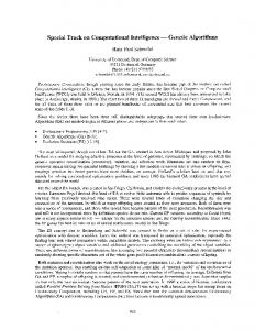
Start
Select unmapped p with max #ops
Add all PEs to feasible(p) No
No
Select least loaded PE from feasible(p)
Remove PE from feasible(p)
Is feasible(p) empty?
No
Mapping p to PE feasible?
Yes
Map p to PE; update PE load
Are all tasks mapped?
Yes Mapping failed
Yes Done
Fig. 2. Load Balancing algorithm [2]
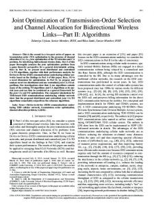
Fig. 3. Longest Processing Time algorithm [2]
For each process element, platform graph reports the speed obtained from PE data models in the IP library. Furthermore, communication costs between process elements are depicted as edge weights in the platform graph. Examples of the application and platform graphs are given in Section IV. With well defined application and platform graph, we can proceed towards the mapping automation with Load Balancing and Longest Processing Time algorithms.
Algorithm itself is quite simple, based upon the Load(PE) function assigned to process elements:
B. Load balancing Load balancing issues have been addressed for many years in general purpose distributed and parallel systems [5], [6]. Since MPSoC exploit parallelism by default, it can also be employed in design of such systems. The basic idea of the algorithm is that all the processing elements in the system are equally loaded, i.e. none of the processing elements are neither overloaded nor underloaded. In this way, number of bottlenecks is reduced and more well balanced system is achieved. As a consequence, overall MPSoC system performance is increased. Algorithm flow [2] is described as follows, Fig 2. Given a profiled application graph and target platform graph, algorithm considers considers following parameters: (i) computational intensity of application tasks given in millions of operations (Mops), (ii) computational speed of processing elements and (iii) feasibility of mapping of a certain task onto platform element. Computational intensity of tasks and speed of processing elements are expressed as node weights in application and platform graph, respectively. Mapping feasibility function feasible(p) of a specific task p computes all processing elements for which mapping of task p is possible. More formally, given a task p and some task q that communicates with p in the application graph, where q is mapped onto processing element PEQ, feasible(p) contains all processing elements that are able to communicate with PEQ.
Load(PE) = Mops(p) / Speed(PE)
(1)
As depicted in Fig. 2, unmapped processes are sorted in descending order according to the number of operations and first task in the list is selected for mapping. For such task, we initialize the feasible(p) list by adding all the processing elements to the list. Consequently, we select the least loaded process in the feasible(p) list, PE and if mapping of p onto PE is feasible, we perform the mapping and update the PE load according to (1). On the other hand, if the mapping is not feasible, given PE is removed from the feasible(p) list. The algorithm ends successfully if all the tasks are mapped or unsuccessfully if the list feasible(p) list is empty for certain unmapped task p. The main drawback of the Load balancing algorithm is that it neglects to consider communication overhead between processing elements, which is important in communication intensive applications. Moreover, algorithm is sensitive to the order in which processes are selected form mapping. Considering that, Load Balancing algorithm does not always yield a valid mapping solution, i.e. according to the given platform model, Load function driven mapping can cause specific processes to remain unmapped. C. Longest Processing Time Longest Processing Time (LPT) algorithm [2] is a highly adopted algorithm in scheduling MPSoC systems [6], [7] however it can also be effectively adapted for task mapping. In comparison to Load Balancing algorithm, LPT considers communication cost between processing elements expressed through edge weights in the platform graph, Fig 5. Moreover, inter-task communication cost in the application graph is also taken into account, Fig 4. LPT is driven by a quality measure C(p,PE) that represents the
cost of mapping a task p onto processing element PE with respect to the PE with currently longest processing time in the system called SystemEndTime. The cost of mapping function C(p,PE) is based upon following factors: (i) current execution end time of a specific process element T(PE), which includes execution times of all processes mapped onto PE and (ii) specific process execution time on a process element E(p, PE):
C(p, PE) = T(PE) + E(p, PE) − SystemEndTime (2) In this way, cost of mapping is scaled according to the process element that represents the system bottleneck at certain point in mapping process. Algorithm is described as follows, Fig 3. Processes are selected for mapping in decreasing order according to the number of operations obtained from profiling, i.e. process computational intensity. In the first step, computationally most consuming task is mapped onto the fastest processing element in the system. That is because in the beginning there is no initial mapping and cost cannot be computed. After the mapping in the first step, cost function can be calculated for the next process in the list of remaining unmapped processes according to (2). In each step, when mapping is saved, current execution times of all process elements are updated and consequently SystemEndTime is chosen. The process is repeated until the list of the unmapped processes is empty. LPT uses simple greedy heuristic and finds a mapping scheme in polynomial amount of time. More specifically, given a multi-processor platform comprised out of M processing elements and application graph with N processes, algorithm is executed in N steps. In each step, cost function is computed and current execution times are updated for M processing elements in the platform graph. This gives O(NM) complexity, however LPT takes sorted list of processes, giving the O(N2logN) complexity. To summarize, complexity of the LPT algorithm is O(N2M). In comparison to Load Balancing algorithm, LPT is more suitable when designing the MPSoC systems with intensive communication requirements. Further comparison of the two algorithms is given in Section IV, where we evaluate the performance of several MPSoC designs obtained using these algorithms.
IV. CASE STUDY In order to evaluate described mapping algorithms, we implemented JPEG encoder [18] benchmark application on a MPSoC platform. The case study implements lossy, baseline JPEG encoding compression method. According to the design flow described in Section II, sequential JPEG C code was first profiled on a MicroBlaze platform within the ESE toolset. As a result, we obtained the application dependency graph comprised out of three tasks, namely JPEG input, DCT and VLC, Fig. 4 a). Application graph shows that DCT is computationally the most intensive task, giving the 1648 Mops, as reported by the profiler. In order to cope with this problem, single DCT task can be further partitioned into two tasks, DCT 1 and DCT 2, each taking the 824 Mops. In this way, 2-way interleaved JPEG application graph is obtained, Fig. 4 b).
Fig. 4. JPEG application graphs
Such fine grained application graph is more suitable for mapping on a MPSoC platform because computationally intensive task may be partitioned over multiple processing elements. With further DCT task partitioning, 3-way interleaved application graph is obtained, Fig. 4 c). In addition to computation profiling, ESE profiling provides information about communication costs between the application tasks. As shown in Fig. 4, communication costs between the DCT and VLC task are two times higher than between the JPEG input and DCT tasks. With well-defined application graph, corresponding platform graph is defined according to the ESE component library, comprised out of MicroBlaze soft processor, Open Peripheral Bus (OPB) and ESE transducer communication interface. For evaluation of the mapping procedures, two homogeneous platform graphs are employed, i.e. 3xMB and 4xMB comprised out of three and four MicroBlaze process elements, receptively, Fig 5 a) and b). For both platform graphs, processing elements are connected using single OPB bus. Communication costs between any two nodes in both graphs are, therefore, equal and correspond to the speed at which single byte of data is transacted over the OPB bus. Mapping engine results of the proposed application and platform graphs, as well as the overall MPSoC synthesis results are discussed in the following section.
Fig. 5. Platform graphs
TABLE I JPEG MAPPING EVALUATION RESULTS Design Application
Platform
Sequential
1xMB 3xMB
2-way 4xMB 3xMB 3-way 4xMB
Alg.
Mapping scheme
ET
vs. LB
vs. LPT
VAR
2,305
-
-
1
1,090
-
0.90
0.47
1,215
1.11
-
0.53
850 1,215
1.43
0.70 -
0.37 0.53
852 852
1
1 -
0.37 0.37
V
955
-
1
0.41
V,D
955
1
-
0.41
MB1
MB2
MB3
MB4
(106cycles)
-
J,D,V
-
-
-
LB
J,D
D
V
LPT
J
D
V,D
LB LPT
J J
D D
D -
LB LPT
J,D J,D
D D
V,D V,D
LB
J,D
D
D
LPT
J
D
D
A. Experimental results In the mapping evaluation process, we synthesized and simulated defined application and platform graphs in ESE toolset. As a quality measure, overall system performance is used. Table I presents the performance evaluation results for mapping schemes obtained using Load Balancing (LB) and Longest Processing Time (LPT) algorithms. For each design (on the rows) obtained using either LB or LPT algorithms, we report mapping schemes over process elements, MB1 - MB4 (columns). Letters J, D and V represent the application tasks JPEG input, DCT and VLC. For such mapping schemes, we further report the execution time (ET) for a specific algorithm, ratio according to the solution obtained by the other algorithm (vs LB, vs LPT), and variance with respect to the single processor implementation (VAR). Lower VAR values represent better results, i.e. achieved execution time is lower in comparison to the execution time of a single-processor system shown in the first row of the Table I. Experiments show performance evaluation for two 2way and 3-way interleaved JPEG encoder mapped over 3xMB and 4xMB platforms, respectively. For 2-way interleaved JPEG application (Fig. 4. b)), experiments show that Load Balancing (LB) algorithm obtains better results for both platforms. More specifically, for 2-way interleaved JPEG and 3xMB platform obtained designs are 1.11 times faster, while for the 4xMB platform 1.43 times. Load Balancing (LB) algorithm distributes the task loads over the platform processors, giving a J, D; D; V mapping scheme and a variance of VAR = 0.47 for 3xMB platform, and J; D; D; V with variance of VAR=0.37 for 4xMB platform, where semicolons are used as delimiters between process elements. MB1 process element executing the JPEG input task is less loaded than MB3 executing the VLC task. Consequently, the remaining DCT task is mapped onto the MB1 process element. On the other hand, Longest Processing Time (LPT) strives to minimize the communication costs. Since communication cost between the DCT and VLC is higher than the one between the DCT and JPEG input, remaining DCT task is mapped on to the MB4, giving the J; D; D,V and J; D; -; D, V schemes. As shown in Table I, for 4xMB platform, LPT does not utilize all process elements and as a consequence LB generated design is 1.43 times faster,
V V,D -
where variance with respect to the single processor system remains the same as for the 3xMB platform, i.e. VAR = 0.53. In the second experiment, 3-way interleaved JPEG application (Fig. 4. c)) is mapped onto 3xMB and 4xMB platforms. For 3xMB platform, both algorithms obtain the same mapping scheme and consequently execution results with a variance of 0.37. Obtained results are equal to the results obtained by the LB algorithm, but for 4xMB platform and 2-way interleaved application, which classifies this solution as a better one with respect of the chip area. Furthermore, results of the 3-way JPEG for the 4xMB platform yield different mapping schemes, J, D; D; D; V for Load Balancing and J; D; D; D, V for Longest Processing Time. However, these mapping schemes produce the same performance results. Overall experimental results show that for smaller platforms more balanced systems obtain the better performance results, i.e. Load Balancing producer better results, while for larger platform communication costs grow higher, yielding to the approximately equal performance for mapping schemes obtained by the both algorithms.
V. CONCLUSION In this paper, we implemented and compared two mapping algorithms for the synthesis of Multi-Processor System on Chip. Load Balancing (LB) and Longest Processing Time (LPT) algorithms were implemented in order to further automate the MPSoC design flow employed within the Embedded System Environment (ESE) toolset. ESE is a toolset that enables high speed MPSoC design from the C/C++ specification by generating the high speed Transaction Level Model (TLM). Highspeed TLM simulation enables us to rapidly evaluate mapping schemes generated automatically by LB and LPT algorithms and detect possible errors in early stages of design. The effectiveness of our approach is illustrated by experimental results obtained from the JPEG encoder MPSoC design, where automated mapping process enables us to prune the overall design space from infeasible solutions. Experimental results show that for homogeneous MPSoC design, the Load Balancing algorithm obtains better results than Longest Processing Time. That is
because Longest Processing Time is more suited for applications with higher communication costs, e.g. H263 used in internet telephony. In comparison to evolutionary methods which are often employed to solve the MPSoC mapping problem, both algorithms offer a sub-optimal solution, but in a reasonable amount of time. The proposed tradeoff is acceptable because we want to speed up and automate the system synthesis and consequently shorten the time to market. For further work we propose additional research on HW/SW partitioning and scheduling techniques in order to automate the MPSoC synthesis and overall MPSoC design flow. ACKNOWLEDGEMENT The work presented in this paper is developed within the Application-oriented Embedded System Technology project supported by the Unity through Knowledge Fund. Authors wish to thank Danko Ivosevic for support. Finally, special thanks to the Center for Embedded Computer Systems (CECS) for allowing download of the ESE tool-set and Samar Abdi for support.
REFERENCES [1] Zadrija V., Sruk V., “Component-based Specification for Multi-Processor System-on-Chip Design” in IEEE MELECON, 25 - 28 April, 2010, Valletta, Malta, (to be published) [2] Gajski, D., Abdi, S., Gerstlauer, A., Schirner, G. “Embedded System Design. Modeling, Synthesis and Verification”, 2009, 358 p.,ISBN: 978-1-4419-0503-1 [3] Vivekanandarajah, K. and Pilakkat, S. K. 2008. “Task Mapping in Heterogeneous MPSoCs for System Level Design”. In Proceedings of the 13th IEEE international Conference on on Engineering of Complex Computer Systems (March 31 - April 03, 2008). ICECCS. IEEE Computer Society, Washington, DC, 56-65 [4] Dick, R. P. and Jha, N. K. 1997. “MOGAC: a multiobjective genetic algorithm for the co-synthesis of hardware-software embedded systems”. In Proceedings of the 1997 IEEE/ACM international Conference on Computer-Aided Design ,pp. 522-529. [5] E. S. H. Hou, N. Ansari, and H. Ren, “A Genetic Algorithm for Multiprocessor Scheduling,” IEEE Transactions on Parallel and Distributed Systems, vol. 5, no.2, pp.113-120, Feb. 1994. [6] Hoeseok Yang and Soonhoi Ha, "Pipelined Data Parallel Task Mapping/Scheduling Technique for MPSoC", Design Automation and Test in Europe, pp. 69-74, April 2009
[7] D. Gajski, S. Abdi, Y. Hwang, L. Yu, H. Cho and I. Viskic, “ESE Front End 2.0,” University of California, Irvine, Tech. Rep., Sep. 2008. [Online]. Available: http://www.cecs.uci.edu/ ese/publications.html [8] Gerstlauer, A., Peng, J., Shin, D., Gajski, D., Nakamura, A., Araki, D., and Nishihara, Y. 2008. Specify-explorerefine (SER): from specification to implementation. In Proceedings of the 45th Annual Design Automation Conference (Anaheim, California, June 08 - 13, 2008). DAC '08. ACM, New York, NY, 586-591 [9] Daniel D. Gajski, Samar Abdi, Gunar Schirner, Han-su Cho, Yonghyun Hwang, Lochi Yu, Ines Viskic, and QuocViet Dang, "User Manual for Embedded System Environment ESE Version 2.0.0," TR 08-14, December 12, 2008. [10] Prakash, S. and Parker, A. C. 1992. “Synthesis of application-specific heterogeneous multiprocessor systems”. SIGARCH Comput. Archit. News 20, 2 (May. 1992), 434. [11] JGraphT - a free Java Graph Library (2009), [Online] Available: http://www.jgrapht.org/ [12] Fenlason J., Stallman, R. "gprof: The GNU profiler", [Online] Available: http://www.cs.utah.edu/dept/old/texinfo/as/gprof_toc.html [13] Sangiovanni-Vincentelli, A., Carloni, L., De Bernardinis, F., and Sgroi, M. 2004. “Benefits and challenges for platform-based design”. In Proceedings of the 41st Annual Design Automation Conference (San Diego, CA, USA, June 07 - 11, 2004). DAC '04, New York, NY, 409-414 [14] Casavant, T. L. and Kuhl, J. G. 1988. A taxonomy of scheduling in general-purpose distributed computing systems. IEEE Trans. Softw. Eng. 14, 2 (Feb. 1988), 141154. [15] Chang, H. W. and Oldham, W. J. 1995. Dynamic Task Allocation Models for Large Distributed Computing Systems. IEEE Trans. Parallel Distrib. Syst. 6, 12 (Dec. 1995), 1301-1315. [16] Khan, A. A., McCreary, C. L., and Jones, M. S. 1994. A Comparison of Multiprocessor Scheduling Heuristics. In Proceedings of the 1994 international Conference on Parallel Processing - Volume 02 (August 15 - 19, 1994). ICPP. IEEE Computer Society, Washington, DC, 243-250. [17] Nguyen Duc Thai, "Real-Time Scheduling in Distributed Systems," Parallel Computing in Electrical Engineering, International Conference on, p. 165, International Conference on Parallel Computing in Electrical Engineering (PARELEC'02), 2002 [18] V. Zadrija and V. Sruk, “Design Space Exploration of a Multi-core JPEG,” in Proceedings of MIPRO 2009, 32nd International Convention, Vol. III., CTS & CIS, 2009, pp. 60–65.