solutions for single components - e. g. spiral case, tandem cascade, runner, draft tube - are applied in the daily business. Also steady state coupled simulations ...
Proceedings of the Hydraulic Machinery and Systems 21st IAHR Symposium September 9-12, 2002, Lausanne
MASSIVLELY PARALLEL COMPUTATION OF THE FLOW IN HYDRO TURBINES Albert RUPRECHT,
Institute of Fluid Mechanics and Hydraulic Machinery / University of Stuttgart, Stuttgart, Germany
Martin MAIHÖFER,
Institute of Fluid Mechanics and Hydraulic Machinery / University of Stuttgart, Stuttgart, Germany
Matthias HEITELE,
Institute of Fluid Mechanics and Hydraulic Machinery / University of Stuttgart, Stuttgart, Germany
Thomas HELMRICH,
Institute of Fluid Mechanics and Hydraulic Machinery / University of Stuttgart, Stuttgart, Germany
ABSTRACT Different numerical procedures for massively parallel simulations in hydraulic machinery are presented. The necessary parallelization models for modern high-performance computers are discussed and their performances evaluated. A special attention is paid to rotor/stator interaction. Thus different numerical schemes are discussed for this non-matching, moving grid problems. The coupling by application of dynamic boundary conditions is shown on the example of a Francis turbine.
RÉSUMÉ Différentes procédures numériques pour la simulation massivement parallèle de machines hydrauliques sont présentées. Les indispensables modèles de parallèlisation pour des calculateurs modernes à hautes performances sont étudiés et leurs capacités évaluées. Une attention particulière est portée sur l’interaction ‘rotor/stator’. Différentes modèles numériques, adaptés à ces domaines de calcul incompatibles et mouvants, sont discutés. Le couplage par l’utilisation de conditions limites dynamiques est illustré par un exemple mettant en œuvre une turbine de type Francis.
INTRODUCTION Today CFD is intensively used in hydro machinery design and research. Steady state solutions for single components - e. g. spiral case, tandem cascade, runner, draft tube - are applied in the daily business. Also steady state coupled simulations of two and more components or of the complete turbine are carried out frequently. Steady state simulations can only be applied, when using an averaging procedure at the interface between rotating and non-rotating parts. These approaches are used today in the design process. Many problems and turbine failures result from dynamic conditions and vibrations. For the investigation of unsteady effects like • dynamic loading,
st
Proceedings of the Hydraulic Machinery and Systems 21 IAHR Symposium September 9-12, 2002, Lausanne
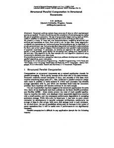
• vortex shedding, • vortex movement, • instabilities (e.g. rotating stall in pumps) time dependent simulations are necessary. Because of the unequal pitching of runner and guide vanes usually no periodicity of the flow can be assumed, consequently all flow passages have to be considered. For a typical Francis turbine the number of guide vanes passages is in the range of 18-24 and the number of runner passages ranges between 7 and 13. All this passages have to be modeled, what leads to computational grids of several million nodes. These simulations can only be performed, when using powerful computers, either high-performance computers or huge clusters. The use of massively parallel computer architectures requires special algorithms. Therefore the goal of this paper is to discuss different algorithms and to highlight some special requirements for massively parallel computations. TURBULENCE MODELING The prediction of unsteady flow – especially of unsteady vortex movement – requires more accurate turbulence models than for steady state calculations. The reason for that is that many of the turbulence models, e. g. k-ε model, are too dissipative and lead to a severe damping of the unsteady motion. This can even lead to steady state simulation results even when the physics shows rather strong unsteady vortex movement. For example it is shown in Ref. 1 for the vortex rope in a diffuser. An improvement is obtained by applying multi-scale models, which represent better dissipation of turbulence, e. g. extended model of Kim & Chen (Ref. 2). However this is still not sufficient. Therefore the development of special “unsteady” turbulence models for Very Large Eddy Simulations are subject of current research (e. g. Ref. 3). The application of such model is shown in Ref. 1 For more details concerning turbulence modeling for unsteady flows the reader is referred to Ref. 4. NUMERICAL METHODS FENFLOSS The computations, based on the Reynolds averaged Navier-Stokes equations with an appropriate turbulence mode, are carried out using the CFD-code FENFLOSS. For numerical details the reader is referred to Ruprecht (Ref. 5) and Maihöfer (Ref. 6). Thus only some characteristic features are shortly summarized. The code is based on: • Finite Element Method, hexahedral elements, unstructured grids, • Streamline upwind Petrov-Galerkin formulation, • Modified Uzawa pressure correction or Poisson solver for pressure, • fully implicit time discretisation of 2nd order, • Preconditioned conjugate gradient solver (ILU – BICGSTAB2) ROTOR/STATOR INTERACTION For the simulation of moving grid problems, as occurres in rotor/stator interaction, different methods can be applied. In fig. 1 three algorithms are explained.
22.10.2002
2
st
Proceedings of the Hydraulic Machinery and Systems 21 IAHR Symposium September 9-12, 2002, Lausanne
Fig. 1 Algorithms for rotor/stator interaction In fig.1 a) the method of “snapping” elements is shown. An element row at the interface between fixed and moving grid is distorted according to the grid movement. This distortion is increased until the next following element is in a position, that the connection to that leads to a smaller distortion of the connecting element. This means that the connecting element snaps back to this element. This is shown in fig. 1 a), where a moving grid is schematically shown for three time steps. The advantage of this method is, that no interpolation is necessary. This means that the accuracy of the solution scheme is preserved. The disadvantage, however, is that the grid generation is quite complicated because at the interface the grid structure has to be rather uniform in order to get the connecting elements and to avoid that the snapping elements are too much distorted. Thus for complicated geometries the grid generation is nearly impossible. In fig. 1 b) the method of dynamic boundary conditions is shown. The different parts, rotor and stator, are calculated independently of each other. The coupling is arranged by boundary conditions, which are updated during the iteration. The node values (velocities and turbulence quantities) are interpolated in the elements of the upstream component to the nodes of the downstream part. The pressure, the momentum fluxes and the turbulence fluxes at the interface are integrated in the downstream elements and transferred to the upstream boundary, where they are applied as Neuman boundary conditions. In order to obtain an accurate interpolation and integration slightly over-lapping meshes are applied. This guarantees that all nodes of the downstream part are always inside the upstream mesh and the entire upstream boundary is completely inside the downstream mesh. The explained procedure is implemented in FENFLOSS for rotor/stator problems.
22.10.2002
3
st
Proceedings of the Hydraulic Machinery and Systems 21 IAHR Symposium September 9-12, 2002, Lausanne
The restriction node approach, shown in fig. 1 c), can only be applied for non-overlapping meshes. In FENFLOSS it is applied for grid embedding. It could also be used for moving grids, but because of the discretisation of the interface boundary for rotating geometries this approach can have the difficulty, that part of the nodes are outside of the other domain. This requires an extrapolation to the restriction nodes, which has to be treated very carefully. However for fine grids this problem is not severe. It is also intended to implement this approach in FENFLOSS, since it converges faster than the dynamic boundary method. In this method the two parts are discretised independently of each other. The coupling effect is introduced by additional compulsory conditions, which are obtained by expressing the restriction nodes by the nodes of the other domain. This results in additional restriction matrices, which lead to the following linear equation system
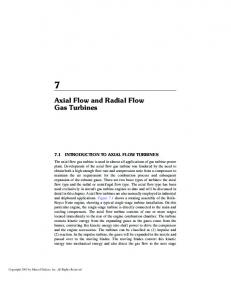
with the system matrices A11 and A22 for the two domains, the unknowns x1 and x2, the Lagrangian multiplier λ, the restriction operators B1 and B2 and the vectors of the right hand side b1 and b2. In case of matching grids, when the restriction nodes are located in the same position than the nodes of the other domain, the restriction operators only express the equality of these nodes. In order to obtain a robust behavior and accurate results the restriction nodes should belong to the finer grid. The nodes of the coarser grid should be treated as degrees of freedom. PARALLELIZATION PROCEDURES For parallel computation two different groups of computer architectures can be distinguished, which requires different parallelization models: • shared memory parallelization, • distributed memory parallelization. Modern powerful architectures combine this two types, see fig. 2. This means that the computer consists of computational nodes with distributed memory in each node. These nodes are combined by a fast communication network. In each node, however, there are several processing units which have a shared memory. This allows to integrate more processors without having a severe bottleneck in the communication. For example the Hitachi SR8000 with 512 nodes and 8 RISC-processors per node reaches a peak performance of 4.9 Tflops with this type of architecture. The shared memory parallelization is quite simple. It works on the basis of loops and is partly performed automatically by the compiler. The parts, which are not automatically recognized by the compiler, can be treated manually by compiler directives. It is required that the algorithm is not recursive. In recent years the OpenMP standard has been established for the compiler directives, so that shared memory parallel programs can be transferred easily from one platform to another. Using distributed memory parallelization each node has only access to its own data. If it requires data from another processor, the programmer is responsible for the communication. He has to organize the data exchange. Therefore, the distributed memory parallelization
22.10.2002
4
st
Proceedings of the Hydraulic Machinery and Systems 21 IAHR Symposium September 9-12, 2002, Lausanne
requires a higher programming effort compared to shared memory parallelization. For organizing the data exchange standard libraries are available. The commonly used one is MPI (Message Passing Interface), which is also applied in FENFLOSS. The MPI approach can also be applied for shared memory machines, however it is not as effective as using OpenMP.
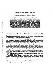
Fig. 2 Architecture of modern high-performance computers In fig. 3 two different methods for distributed memory parallelization are presented. The first one is the Schur-complement method (left). Here the different domains are calculated independently of each other. The coupling is introduced by an equality relation of the boundary nodes. This relation is expressed by the introduction of Lagrangian multipliers and is fulfilled by solving a linear system of equation for these multipliers. The advantage of this method is, that no overlapping elements are needed. This is quite convenient for complex problems. The mayor disadvantage, however, is that the method converges much slower than the other method shown in fig 3. (right) using overlapping elements.
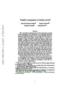
Fig. 3 Distributed memory parallelisation The second method is implemented in FENFLOSS. By using overlapping elements correct equations for all nodes of the core domain can be obtained on each processor and is introduced into a complete system matrix. The coupled system can be solved using a parallel conjugate gradient solver. In fig. 4 the speedup on a HITACHI SR8000 is shown for a turbulent flow simulation in a draft tube. Using 8 processors (only OpenMP parallelisation is applied) it can be seen that the speedup reaches 7.33, which shows an excellent performance. Applying only MPI the speedup is reduced to 5.83 due to communication. As can be seen in fig. 4 a combination of MPI and OpenMP is necessary on this machine in order to get a good performance.
22.10.2002
5
st
Proceedings of the Hydraulic Machinery and Systems 21 IAHR Symposium September 9-12, 2002, Lausanne
Fig. 4 Speedup of FENFLOSS ROTOR/STATOR INTERFACE Applying domain decomposition to a moving grid problem leads to an other difficulty. A rotor / stator problem is shown schematically in fig. 5 (left). The computational grid is distributed to different processors (different colors represent different processors). As it can be seen during the calculation the connectivity of the runner nodes to the stator nodes changes. This requires dynamic communication tables. In the case of using restriction operators this would lead to a different matrix structure in each time step, which is more difficult to implement than the dynamic boundary approach.
Fig. 5. Moving grid parallelization The data exchange, as organized in FENFLOSS, is also shown in fig. 5 (right). The necessary boundary condition information is sent to each processor of the other domain. From this data each processor can interpolate its own boundary conditions. In fig. 6 the flow chart of FENFLOSS is summarized including the parallel data exchange. FLOW IN A FRANCIS TURBINE In the following the application of parallel high performance computing is shown for a Francis turbine. The meshes of the different parts and the data exchange is shown in fig. 7. Each component is calculated in parallel and the coupling between the components is
22.10.2002
6
st
Proceedings of the Hydraulic Machinery and Systems 21 IAHR Symposium September 9-12, 2002, Lausanne
obtained by dynamic boundary conditions. The computation is carried out on 96 processor of a CRAY T3E.
Fig. 6 Flow chart of FENFLOSS
Fig. 7 Parallel simulation of a Francis turbine By applying a time-dependent simulation unsteady effects can be obtained. In fig. 8 the existence of a vortex rope in the draft tube can be seen. Other information, which are obtained, are dynamic loading. As an example the torque of a single blade is shown In fig. 9. The variation in time shows the dynamic loading acting on the blade. CONCLUSION Different numerical methods for massively parallel simulations in hydraulic machinery are presented. The application of combined shared and distributed memory architectures, which are installed in modern high-performance computers, show that it is necessary to take this into account in order to get a good performance. Special attention is paid to the rotor/stator
22.10.2002
7
st
Proceedings of the Hydraulic Machinery and Systems 21 IAHR Symposium September 9-12, 2002, Lausanne
interaction. The application of dynamic boundary conditions is easier to implement and robust to handle and thus it is used.
Fig. 8 Vortex rope in the draft tube
Fig 9. Torque on a single runner blade REFERENCES Ref. 1
Ruprecht, A., Helmrich, Th., Aschenbrenner, Th., Scherer, Th., 2002, " Simulation of Vortex Rope in a Turbine Draft Tube”, Proceedings of 21st I.A.H.R. Symposium on Hydraulic Machinery and Cacitation, Lausanne.
Ref. 2
Kim, S.-W., Chen, C.-P., 1989, “A multiple-time-scale turbulence model based on variable partitioning of the turbulent kinetic energy spectrum”, Numerical Heat Transfer 16(B).
Ref. 3
Magnato, F., Gabi, M., 2000, “A new adaptive turbulence model for unsteady flow fields in rotating machinery”, ISROMAC 8.
Ref. 4
Ruprecht, A., 2002, „Numerische Strömungssimulation am Beispiel hydraulischer Strömungsmaschinen“, Habilitationsschrift, Universität Stuttgart.
Ref. 5
Ruprecht, A., 1989, „Finite Elemente zur Berechnung dreidimensionaler, turbulenter Strömungen in komplexen Geometrien“, Dissertation, Universität Stuttgart.
Ref. 6
Maihöfer, M. (2002), „Effiziente Verfahren zur Berechnung dreidimensionaler Strömungen mit nichtpassenden Gittern, Dissertation, Universität Stuttgart.
Ref. 7
Van der Vorst, H. A., (1994), Recent Developments in Hybrid CG Methods, Proc. High Performance Computing & Networking, München.
22.10.2002
8